Manual
Page 5
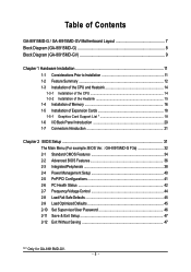
Table of Contents GA-8I915MD-G / GA-8I915MD-GV Motherboard Layout 7 Block Diagram (GA-8I915MD-G 8 Block Diagram (GA-8I915MD-GV 9 Chapter 1 Hardware Installation 11 1-1 Considerations Prior to Installation 11 1-2 Feature Summary 12 1-3 ...BIOS Features 36 2-3 IntegratedPeripherals 38 2-4 Power Management Setup 40 2-5 PnP/PCI Configurations 41 2-6 PC Health Status 42 2-7 Frequency/Voltage Control 44 2-8 Load Fail-Safe Defaults 45 2-9 Load Optimized Defaults 45 2-10 Set Supervisor/User Password 46 2-11 Save & Exit Setup 47 2-12 Exit Without Saving 47 "*" Only for GA-8I915MD-GV...
Table of Contents GA-8I915MD-G / GA-8I915MD-GV Motherboard Layout 7 Block Diagram (GA-8I915MD-G 8 Block Diagram (GA-8I915MD-GV 9 Chapter 1 Hardware Installation 11 1-1 Considerations Prior to Installation 11 1-2 Feature Summary 12 1-3 ...BIOS Features 36 2-3 IntegratedPeripherals 38 2-4 Power Management Setup 40 2-5 PnP/PCI Configurations 41 2-6 PC Health Status 42 2-7 Frequency/Voltage Control 44 2-8 Load Fail-Safe Defaults 45 2-9 Load Optimized Defaults 45 2-10 Set Supervisor/User Password 46 2-11 Save & Exit Setup 47 2-12 Exit Without Saving 47 "*" Only for GA-8I915MD-GV...
Manual
Page 6
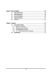
Chapter 3 Drivers Installation 49 3-1 Install Chipset Drivers 49 3-2 SoftwareApplications 50 3-3 Driver CD Information 50 3-4 Hardware Information 51 3-5 Contact Us ...51 Chapter 4 Appendix 53 4-1 Unique Software Utilities 53 4-1-1 EasyTune 5 Introduction 54 4-1-2 Xpress Recovery2 Introduction 55 4-1-3 Flash BIOS Method Introduction 57 4-1-4 2 / 4 / 6 Channel Audio Function Introduction 66 4-2 Troubleshooting 72 - 6 -
Chapter 3 Drivers Installation 49 3-1 Install Chipset Drivers 49 3-2 SoftwareApplications 50 3-3 Driver CD Information 50 3-4 Hardware Information 51 3-5 Contact Us ...51 Chapter 4 Appendix 53 4-1 Unique Software Utilities 53 4-1-1 EasyTune 5 Introduction 54 4-1-2 Xpress Recovery2 Introduction 55 4-1-3 Flash BIOS Method Introduction 57 4-1-4 2 / 4 / 6 Channel Audio Function Introduction 66 4-2 Troubleshooting 72 - 6 -
Manual
Page 7
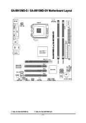
Only for GA-8I915MD-G. GA-8I915MD-G / GA-8I915MD-GV Motherboard Layout KB_MS ATX_12V LGA775 CPU_FAN ATX CI IDE1 IT8712 COMA GA-8I915MD-G or GA-8I915MD-GV LPT LAN VGA USB DDRII2 PWR_LED F_PANEL USB AUDIO Intel 915G / Intel 915GV PCIE_16 RTL8110S / RTL8100C CD_IN CODEC AUX_IN F_AUDIO SUR_CEN SPDIF_IO COMB PCI1 PCI2 Intel ICH6 PCI3 SYS_FAN F_USB1 F_USB2 DDRII1 FDD SATA1 SATA0 BIOS BAT CLR_CMOS Only for GA-8I915MD-GV. - 7 -
Only for GA-8I915MD-G. GA-8I915MD-G / GA-8I915MD-GV Motherboard Layout KB_MS ATX_12V LGA775 CPU_FAN ATX CI IDE1 IT8712 COMA GA-8I915MD-G or GA-8I915MD-GV LPT LAN VGA USB DDRII2 PWR_LED F_PANEL USB AUDIO Intel 915G / Intel 915GV PCIE_16 RTL8110S / RTL8100C CD_IN CODEC AUX_IN F_AUDIO SUR_CEN SPDIF_IO COMB PCI1 PCI2 Intel ICH6 PCI3 SYS_FAN F_USB1 F_USB2 DDRII1 FDD SATA1 SATA0 BIOS BAT CLR_CMOS Only for GA-8I915MD-GV. - 7 -
Manual
Page 8
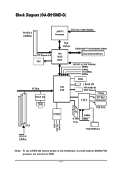
Block Diagram (GA-8I915MD-G) PCI-ECLK (100MHz) LGA775 Processor CPUCLK+/-(200/133MHz) PCI Express x16 VGA PCI Bus RTL8110S RJ45 Host Interface DDRII 600(Note)/533/400MHz DIMM Intel 915G MCH Dual Channel Memory MCHCLK (200/133MHz) 66MHz 33MHz 14.318MHz 48MHz BIOS 2 Serial ATA Intel ATA33/66/100 ICH6 IDE1 Channel Floppy IT8712 LPT Port COM Ports 3 PCI CODEC 8 USB Ports 24MHz 33MHz PS/2 KB/Mouse MIC Line-Out Line-In PCICLK (33MHz) (Note) To use a DDRII 600 memory module on the motherboard, you must install an 800MHz FSB processor and overclock in BIOS. - 8 -
Block Diagram (GA-8I915MD-G) PCI-ECLK (100MHz) LGA775 Processor CPUCLK+/-(200/133MHz) PCI Express x16 VGA PCI Bus RTL8110S RJ45 Host Interface DDRII 600(Note)/533/400MHz DIMM Intel 915G MCH Dual Channel Memory MCHCLK (200/133MHz) 66MHz 33MHz 14.318MHz 48MHz BIOS 2 Serial ATA Intel ATA33/66/100 ICH6 IDE1 Channel Floppy IT8712 LPT Port COM Ports 3 PCI CODEC 8 USB Ports 24MHz 33MHz PS/2 KB/Mouse MIC Line-Out Line-In PCICLK (33MHz) (Note) To use a DDRII 600 memory module on the motherboard, you must install an 800MHz FSB processor and overclock in BIOS. - 8 -
Manual
Page 9
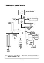
Block Diagram (GA-8I915MD-GV) LGA775 Processor CPUCLK+/-(200/133MHz) VGA PCI-ECLK (100MHz) PCI Express x4 PCI Bus RTL8100C RJ45 Host Interface Intel 915GV MCH DDRII 600(Note)533/400MHz DIMM Dual Channel Memory MCHCLK (200/133MHz) 66MHz 33MHz 14.318MHz 48MHz BIOS 2 Serial ATA Intel ATA33/66/100 ICH6 IDE1 Channel Floppy IT8712 LPT Port COM Ports 3 PCI CODEC 8 USB Ports 24MHz 33MHz PS/2 KB/Mouse MIC Line-Out Line-In PCICLK (33MHz) (Note) To use a DDRII 600 memory module on the motherboard, you must install an 800MHz FSB processor and overclock in BIOS. - 9 -
Block Diagram (GA-8I915MD-GV) LGA775 Processor CPUCLK+/-(200/133MHz) VGA PCI-ECLK (100MHz) PCI Express x4 PCI Bus RTL8100C RJ45 Host Interface Intel 915GV MCH DDRII 600(Note)533/400MHz DIMM Dual Channel Memory MCHCLK (200/133MHz) 66MHz 33MHz 14.318MHz 48MHz BIOS 2 Serial ATA Intel ATA33/66/100 ICH6 IDE1 Channel Floppy IT8712 LPT Port COM Ports 3 PCI CODEC 8 USB Ports 24MHz 33MHz PS/2 KB/Mouse MIC Line-Out Line-In PCICLK (33MHz) (Note) To use a DDRII 600 memory module on the motherboard, you must install an 800MHz FSB processor and overclock in BIOS. - 9 -
Manual
Page 12
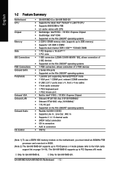
... 1) To use a DDRII 600 memory module on the motherboard, you must install an 800MHz FSB processor and overclock in BIOS. (Note 2) The GA-8I915MD-GV supports up to 2GB memory) Š Supports 1.8V DDR II DIMM Š Supports dual channel DDR II 600(Note... on the Win 2000/XP operating systems Š Realtek ALC655 CODEC Š Supports Line In ; Only for GA-8I915MD-GV. Only for GA-8I915MD-G. Line Out ; GA-8I915MD-G/GA-8I915MD-GV Motherboard - 12 - English 1-2 Feature Summary Motherboard CPU Chipset Memory Slots IDE Connections FDD Connections Onboard SATA Peripherals Onboard...
... 1) To use a DDRII 600 memory module on the motherboard, you must install an 800MHz FSB processor and overclock in BIOS. (Note 2) The GA-8I915MD-GV supports up to 2GB memory) Š Supports 1.8V DDR II DIMM Š Supports dual channel DDR II 600(Note... on the Win 2000/XP operating systems Š Realtek ALC655 CODEC Š Supports Line In ; Only for GA-8I915MD-GV. Only for GA-8I915MD-G. Line Out ; GA-8I915MD-G/GA-8I915MD-GV Motherboard - 12 - English 1-2 Feature Summary Motherboard CPU Chipset Memory Slots IDE Connections FDD Connections Onboard SATA Peripherals Onboard...
Manual
Page 13
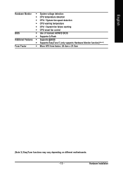
Hardware Installation English Hardware Monitor Š System voltage detection Š CPU temperature detection Š CPU / System fan speed detection Š CPU warning temperature Š CPU / System fan failure warning Š CPU smart fan control BIOS Š Use of licensed AWARD BIOS Š Supports Q-Flash Additional Features Š Supports @BIOS Š Supports EasyTune 5 (only supports Hardware Monitor function)(Note 3) Form Factor Š Micro ATX form factor; 24.4cm x 21.5cm (Note 3) EasyTune functions may vary depending on different motherboards. - 13 -
Hardware Installation English Hardware Monitor Š System voltage detection Š CPU temperature detection Š CPU / System fan speed detection Š CPU warning temperature Š CPU / System fan failure warning Š CPU smart fan control BIOS Š Use of licensed AWARD BIOS Š Supports Q-Flash Additional Features Š Supports @BIOS Š Supports EasyTune 5 (only supports Hardware Monitor function)(Note 3) Form Factor Š Micro ATX form factor; 24.4cm x 21.5cm (Note 3) EasyTune functions may vary depending on different motherboards. - 13 -
Manual
Page 14
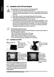
... Enabling the functionality of Hyper-Threading Technology for your hardware specifications including the CPU, graphics card, memory, hard drive, etc. BIOS: A BIOS that has optimizations for the peripherals. OS: An operation system that supports HT Technology and has it does not meet the required...a straight and downwards motion. Fig. 3 Notice the small gold colored triangle located on the CPU socket to the CPU during installation.) GA-8I915MD-G/GA-8I915MD-GV Motherboard - 14 - Fig. 4 Once the CPU is installed on the CPU socket. Please set beyond the proper specifications, please do...
... Enabling the functionality of Hyper-Threading Technology for your hardware specifications including the CPU, graphics card, memory, hard drive, etc. BIOS: A BIOS that has optimizations for the peripherals. OS: An operation system that supports HT Technology and has it does not meet the required...a straight and downwards motion. Fig. 3 Notice the small gold colored triangle located on the CPU socket to the CPU during installation.) GA-8I915MD-G/GA-8I915MD-GV Motherboard - 14 - Fig. 4 Once the CPU is installed on the CPU socket. Please set beyond the proper specifications, please do...
Manual
Page 16
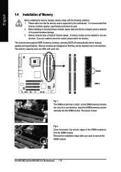
... damage. 3. If you wish to insert the module, please switch the direction. The motherboard supports DDR II memory modules, whereby BIOS will automatically detect memory capacity and specifications. Notch DDR II Fig.1 The DIMM socket has a notch, so the DIMM memory module... DIMM module. Insert the DIMM memory module vertically into the DIMM socket. A memory module can differ with the following conditions: 1. GA-8I915MD-G/GA-8I915MD-GV Motherboard - 16 - Before installing or removing memory modules, please make sure that the memory used is recommended that memory of similar capacity...
... damage. 3. If you wish to insert the module, please switch the direction. The motherboard supports DDR II memory modules, whereby BIOS will automatically detect memory capacity and specifications. Notch DDR II Fig.1 The DIMM socket has a notch, so the DIMM memory module... DIMM module. Insert the DIMM memory module vertically into the DIMM socket. A memory module can differ with the following conditions: 1. GA-8I915MD-G/GA-8I915MD-GV Motherboard - 16 - Before installing or removing memory modules, please make sure that the memory used is recommended that memory of similar capacity...
Manual
Page 18
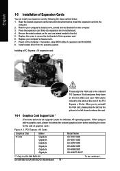
Power on the computer, if necessary, setup BIOS utility of the expansion card. 6. PCI Express x16 Cards Graphics Chip Nvidia Maker Gigabyte Gigabyte Gigabyte Gigabyte Gigabyte Gigabyte Model Name GV-NX53128D GV-NX57128D GV-NX59128D GV-NX62128D GV-NX66256D GV-NX66T128VP "*" Only for the add-on graphics card, please...by following the steps outlined below are indeed seated in motherboard. 4. Be sure the metal contacts on the slot. GA-8I915MD-G/GA-8I915MD-GV Motherboard - 18 - When using an add-on graphics card.) Figure 1-1. Replace the screw to the onboard PCI Express...
Power on the computer, if necessary, setup BIOS utility of the expansion card. 6. PCI Express x16 Cards Graphics Chip Nvidia Maker Gigabyte Gigabyte Gigabyte Gigabyte Gigabyte Gigabyte Model Name GV-NX53128D GV-NX57128D GV-NX59128D GV-NX62128D GV-NX66256D GV-NX66T128VP "*" Only for the add-on graphics card, please...by following the steps outlined below are indeed seated in motherboard. 4. Be sure the metal contacts on the slot. GA-8I915MD-G/GA-8I915MD-GV Motherboard - 18 - When using an add-on graphics card.) Figure 1-1. Replace the screw to the onboard PCI Express...
Manual
Page 24
.... Please refer to the BIOS setting for information on settings, please refer to the instructions located on one IDE cable, and the single IDE cable can provide up to two IDE devices (hard drive or optical drive). Pin No. Definition 1 GND 2 TXP 3 TXN 4 GND 1 7 5 RXN 6 RXP 7 GND GA-8I915MD-G/GA-8I915MD-GV Motherboard - 24 - English 6) IDE1...
.... Please refer to the BIOS setting for information on settings, please refer to the instructions located on one IDE cable, and the single IDE cable can provide up to two IDE devices (hard drive or optical drive). Pin No. Definition 1 GND 2 TXP 3 TXN 4 GND 1 7 5 RXN 6 RXP 7 GND GA-8I915MD-G/GA-8I915MD-GV Motherboard - 24 - English 6) IDE1...

Manual
Page 29
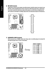
Check the pin assignments while you connect the COMB cable. You can check the "Case Opened" status in BIOS Setup. Hardware Installation English 16) COMB (COMB Connector) Be careful with the polarity of the COMB connector. Pin No. Definition 1 1 Signal 2 GND - 29 - Please contact your nearest dealer for optional COMB cable. 2 10 1 9 Pin No. 1 2 3 4 5 6 7 8 9 10 Definition NDCDBNSINB NSOUTB NDTRBGND NDSRBNRTSBNCTSBNRIBNo Pin 17) CI (Chassis Intrusion, Case Open) This 2-pin connector allows your system to detect if the chassis cover is removed.
Check the pin assignments while you connect the COMB cable. You can check the "Case Opened" status in BIOS Setup. Hardware Installation English 16) COMB (COMB Connector) Be careful with the polarity of the COMB connector. Pin No. Definition 1 1 Signal 2 GND - 29 - Please contact your nearest dealer for optional COMB cable. 2 10 1 9 Pin No. 1 2 3 4 5 6 7 8 9 10 Definition NDCDBNSINB NSOUTB NDTRBGND NDSRBNRTSBNCTSBNRIBNo Pin 17) CI (Chassis Intrusion, Case Open) This 2-pin connector allows your system to detect if the chassis cover is removed.
Manual
Page 31
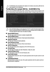
.... If you wish to upgrade to quickly and easily update or backup BIOS without entering the operating system. @BIOS is displayed at the bottom of the screen. Q-Flash allows the user to a new BIOS, either GIGABYTE's Q-Flash or @BIOS utility can enter the BIOS setup screen by pressing "Ctrl + F1". Exit current page and return to...
.... If you wish to upgrade to quickly and easily update or backup BIOS without entering the operating system. @BIOS is displayed at the bottom of the screen. Q-Flash allows the user to a new BIOS, either GIGABYTE's Q-Flash or @BIOS utility can enter the BIOS setup screen by pressing "Ctrl + F1". Exit current page and return to...
Manual
Page 32
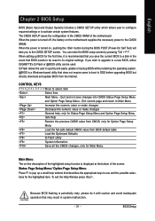
... from the exact settings for stability. „ Standard CMOS Features This setup page includes all the items in standard compatible BIOS. „ Advanced BIOS Features This setup page includes all the items of Award special enhanced features. „ Integrated Peripherals This setup page includes ... or enter the sub-menu. If you can't find the setting you enter Award BIOS CMOS Setup Utility, the Main Menu (as usual. GA-8I915MD-G/GA-8I915MD-GV Motherboard - 32 - The Main Menu (For example: BIOS Ver. : GA-8I915MD-G F3a) Once you want, please press "Ctrl+F1" to search the advanced option...
... from the exact settings for stability. „ Standard CMOS Features This setup page includes all the items in standard compatible BIOS. „ Advanced BIOS Features This setup page includes all the items of Award special enhanced features. „ Integrated Peripherals This setup page includes ... or enter the sub-menu. If you can't find the setting you enter Award BIOS CMOS Setup Utility, the Main Menu (as usual. GA-8I915MD-G/GA-8I915MD-GV Motherboard - 32 - The Main Menu (For example: BIOS Ver. : GA-8I915MD-G F3a) Once you want, please press "Ctrl+F1" to search the advanced option...

Manual
Page 33
It allows you to limit access to the system. „ Save & Exit Setup Save CMOS value settings to Setup. „ Set User Password Change, set , or disable password. BIOS Setup It allows you to limit access to the system and Setup, or just to CMOS and exit setup. „ Exit Without Saving Abandon all CMOS value changes and exit setup. - 33 - English „ Set Supervisor Password Change, set , or disable password.
It allows you to limit access to the system. „ Save & Exit Setup Save CMOS value settings to Setup. „ Set User Password Change, set , or disable password. BIOS Setup It allows you to limit access to the system and Setup, or just to CMOS and exit setup. „ Exit Without Saving Abandon all CMOS value changes and exit setup. - 33 - English „ Set Supervisor Password Change, set , or disable password.

Manual
Page 34
...Auto(default:Auto) Capacity Capacity of currently installed hard disk. Extend IDE Drive You can use one of the two methods: • Auto Allows BIOS to automatically detect IDE devices during POST(default) • None Select this to Dec. Halt On Base Memory Extended Memory Total Memory [All, But...IDE Channel 2 Master ` IDE Channel 3 Master Drive A Drive B Floppy 3 Mode Support [None] [None] [None] [None] [1.44M, 3.5"] [None] [Disabled] Change the day, month, year Sun. GA-8I915MD-G/GA-8I915MD-GV Motherboard - 34 - to set the access mode for the hard drive. Through Dec.
...Auto(default:Auto) Capacity Capacity of currently installed hard disk. Extend IDE Drive You can use one of the two methods: • Auto Allows BIOS to automatically detect IDE devices during POST(default) • None Select this to Dec. Halt On Base Memory Extended Memory Total Memory [All, But...IDE Channel 2 Master ` IDE Channel 3 Master Drive A Drive B Floppy 3 Mode Support [None] [None] [None] [None] [1.44M, 3.5"] [None] [Disabled] Change the day, month, year Sun. GA-8I915MD-G/GA-8I915MD-GV Motherboard - 34 - to set the access mode for the hard drive. Through Dec.

Manual
Page 35
... All, But Disk/Key The system boot will stop for all other errors. No Errors The system boot will determine the amount of the BIOS. BIOS Setup English Hard drive information should be labeled on this information. it will stop for all other All, But Diskette errors. (Default value)... boot will not stop for systems with 640K or more memory installed on the motherboard, or 640K for a disk error; Extended Memory The BIOS determines how much extended memory is determined by POST (Power On Self Test) of base (or conventional) memory installed in the CPU's memory...
... All, But Disk/Key The system boot will stop for all other errors. No Errors The system boot will determine the amount of the BIOS. BIOS Setup English Hard drive information should be labeled on this information. it will stop for all other All, But Diskette errors. (Default value)... boot will not stop for systems with 640K or more memory installed on the motherboard, or 640K for a disk error; Extended Memory The BIOS determines how much extended memory is determined by POST (Power On Self Test) of base (or conventional) memory installed in the CPU's memory...
Manual
Page 36
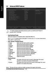
... USB-FDD. USB-ZIP Select your boot device priority by USB-ZIP. USB-CDROM Select your boot device priority by USB-CDROM. GA-8I915MD-G/GA-8I915MD-GV Motherboard - 36 - to move it down the list. Press to Setup page if the correct password is not entered at the ... First / Second / Third Boot Device Floppy Select your boot device priority by Floppy. English 2-2 Advanced BIOS Features CMOS Setup Utility-Copyright (C) 1984-2005 Award Software Advanced BIOS Features ` Hard Disk Boot Priority First Boot Device Second Boot Device Third Boot Device Password Check CPU Hyper...
... USB-FDD. USB-ZIP Select your boot device priority by USB-ZIP. USB-CDROM Select your boot device priority by USB-CDROM. GA-8I915MD-G/GA-8I915MD-GV Motherboard - 36 - to move it down the list. Press to Setup page if the correct password is not entered at the ... First / Second / Third Boot Device Floppy Select your boot device priority by Floppy. English 2-2 Advanced BIOS Features CMOS Setup Utility-Copyright (C) 1984-2005 Award Software Advanced BIOS Features ` Hard Disk Boot Priority First Boot Device Second Boot Device Third Boot Device Password Check CPU Hyper...

Manual
Page 37
... windows XP.(Default value) No-Execute Memory Protect (Note) Enabled Enable No-Execute Memory Protect function.(Default value) Disabled Disable No-Execute Memory Protect function. BIOS Setup On-Chip Frame Buffer Size 1MB Set On-chip frame buffer size to 1MB. 4MB Set On-chip frame buffer size to 4MB. 8MB...
... windows XP.(Default value) No-Execute Memory Protect (Note) Enabled Enable No-Execute Memory Protect function.(Default value) Disabled Disable No-Execute Memory Protect function. BIOS Setup On-Chip Frame Buffer Size 1MB Set On-chip frame buffer size to 1MB. 4MB Set On-chip frame buffer size to 4MB. 8MB...
Manual
Page 38
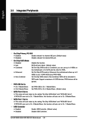
...-Combined Disable this function will be simulated to Ch. 1 Master/Slave, this function. PATA devices will auto set to PATA mode. SATA Port 1 Set to ". GA-8I915MD-G/GA-8I915MD-GV Motherboard - 38 - Set On-Chip SATA mode to Non-Combined, SATA will auto make by the setting "On-Chip SATA Mode" and "PATA IDE Set... Set to SATA Port 0 Set to SATA Port 1 Set to Ch. 1 Master/Slave. If PATA IDE were set to use; 4 SATA HDDs plus PATA HDDs. BIOS will auto set to Ch. 0 Master/Slave, this function will auto detect. (Default value) Set On-Chip SATA mode to Combined, you can use up...
...-Combined Disable this function will be simulated to Ch. 1 Master/Slave, this function. PATA devices will auto set to PATA mode. SATA Port 1 Set to ". GA-8I915MD-G/GA-8I915MD-GV Motherboard - 38 - Set On-Chip SATA mode to Non-Combined, SATA will auto make by the setting "On-Chip SATA Mode" and "PATA IDE Set... Set to SATA Port 0 Set to SATA Port 1 Set to Ch. 1 Master/Slave. If PATA IDE were set to use; 4 SATA HDDs plus PATA HDDs. BIOS will auto set to Ch. 0 Master/Slave, this function will auto detect. (Default value) Set On-Chip SATA mode to Combined, you can use up...


