Manual
Page 4
... 1-3-1 Installation of the CPU 12 1-3-2 Installation of the Heatsink 13 1-4 Installation of Memory 14 1-5 Install expansion cards 16 1-6 I/O Back Panel Introduction 17 1-7 Connectors Introduction 18 Chapter 2 BIOS Setup 29 The Main Menu (For example: BIOS Ver. : E2 30 2-1 Standard CMOS Features 32 2-2 Advanced BIOS Features 34 2-3 IntegratedPeripherals 36 2-4 Power Management Setup 39 2-5 PnP/PCI Configurations 41 2-6 PC Health Status 42 2-7 MB Intelligent Tweaker(M.I.T 43 2-8 Load Fail-Safe Defaults 44 2-9 Load Optimized Defaults 44 2-10 Set Supervisor/User Password 45...
... 1-3-1 Installation of the CPU 12 1-3-2 Installation of the Heatsink 13 1-4 Installation of Memory 14 1-5 Install expansion cards 16 1-6 I/O Back Panel Introduction 17 1-7 Connectors Introduction 18 Chapter 2 BIOS Setup 29 The Main Menu (For example: BIOS Ver. : E2 30 2-1 Standard CMOS Features 32 2-2 Advanced BIOS Features 34 2-3 IntegratedPeripherals 36 2-4 Power Management Setup 39 2-5 PnP/PCI Configurations 41 2-6 PC Health Status 42 2-7 MB Intelligent Tweaker(M.I.T 43 2-8 Load Fail-Safe Defaults 44 2-9 Load Optimized Defaults 44 2-10 Set Supervisor/User Password 45...
Manual
Page 10
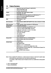
... connector Š 1 PS/2 keyboard port Š 1 PS/2 mouse port Š Onboard Realtek 8110S chip (10/100/1000 Mbit) Š Onboard Realtek 8100C chip (10/100 Mbit) Š 1 RJ 45 port Š ALC880 CODEC Š High Definition Audio Š Supports 2 / 4 / 6 / 8 channel audio Š Supports Line In ; GA-8I915GV-MF/GA-8I915GVM Motherboard - 10 - Surround Speaker Out (Rear Speaker Out) ; Line Out (Front Speaker Out) ; Only for GA-8I915GV-MF. English 1-2 Feature Summary CPU Chipset Memory Slots IDE Connections FDD Connections Onboard SATA Peripherals Onboard LAN Onboard Audio Š...
... connector Š 1 PS/2 keyboard port Š 1 PS/2 mouse port Š Onboard Realtek 8110S chip (10/100/1000 Mbit) Š Onboard Realtek 8100C chip (10/100 Mbit) Š 1 RJ 45 port Š ALC880 CODEC Š High Definition Audio Š Supports 2 / 4 / 6 / 8 channel audio Š Supports Line In ; GA-8I915GV-MF/GA-8I915GVM Motherboard - 10 - Surround Speaker Out (Rear Speaker Out) ; Line Out (Front Speaker Out) ; Only for GA-8I915GV-MF. English 1-2 Feature Summary CPU Chipset Memory Slots IDE Connections FDD Connections Onboard SATA Peripherals Onboard LAN Onboard Audio Š...
Manual
Page 20
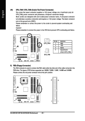
... power connector wire indicates a positive connection and requires a +12V power voltage. The black connector wire is used to the FDD drive. Please remember to connect the power to the cooler to the pin1 position. 34 33 2 1 GA-8I915GV-MF/GA-8I915GVM Motherboard - 20 - Please remember to connect the power to the CPU fan to prevent CPU overheating and failure. 1 CPU_FAN 1 SYS_FAN Pin No. 1 2 3 4 Definition GND +12V Sense Speed Control (Only for CPU_FAN) power connector and possesses a foolproof connection...
... power connector wire indicates a positive connection and requires a +12V power voltage. The black connector wire is used to the FDD drive. Please remember to connect the power to the cooler to the pin1 position. 34 33 2 1 GA-8I915GV-MF/GA-8I915GVM Motherboard - 20 - Please remember to connect the power to the CPU fan to prevent CPU overheating and failure. 1 CPU_FAN 1 SYS_FAN Pin No. 1 2 3 4 Definition GND +12V Sense Speed Control (Only for CPU_FAN) power connector and possesses a foolproof connection...
Manual
Page 21
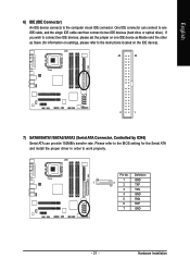
... (Serial ATA Connector, Controlled by ICH6) Serial ATA can then connect to the instructions located on one IDE cable, and the single IDE cable can provide 150MB/s transfer rate. Definition 1 GND 1 7 2 TXP 3 TXN 4 GND 5 RXN 6 RXP 7 GND - 21 - Please refer to the BIOS setting for information on settings, please refer to two IDE devices (hard drive or optical drive). English 6) IDE (IDE Connector) An IDE device connects to work properly. Pin No. One IDE connector can connect to one IDE device as...
... (Serial ATA Connector, Controlled by ICH6) Serial ATA can then connect to the instructions located on one IDE cable, and the single IDE cable can provide 150MB/s transfer rate. Definition 1 GND 1 7 2 TXP 3 TXN 4 GND 5 RXN 6 RXP 7 GND - 21 - Please refer to the BIOS setting for information on settings, please refer to two IDE devices (hard drive or optical drive). English 6) IDE (IDE Connector) An IDE device connects to work properly. Pin No. One IDE connector can connect to one IDE device as...
Manual
Page 22
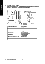
.../ Power/ Sleep LED Power Switch Speaker Connector SPEAK- HDHD+ HD (IDE Hard Disk Active LED) SPEAK (Speaker Connector) RES (Reset Switch) PW (Power Switch) MSG(Message LED/Power/Sleep LED) NC IDE Hard Disk Active LED Reset Switch Pin 1: LED anode(+) Pin 2: LED cathode(-) Pin 1: VCC(+) Pin 2- SPEAK+ PWPW+ MSGMSG+ 2 20 1 19 NCRES+ RES- Pin 3: NC Pin 4: Data(-) Open: Normal Operation Close: Reset Hardware System Open: Normal Operation Close: Power On/Off Pin 1: LED anode(+) Pin 2: LED cathode(-) NC GA-8I915GV-MF/GA-8I915GVM Motherboard - 22 - English 8) F_PANEL (Front Panel...
.../ Power/ Sleep LED Power Switch Speaker Connector SPEAK- HDHD+ HD (IDE Hard Disk Active LED) SPEAK (Speaker Connector) RES (Reset Switch) PW (Power Switch) MSG(Message LED/Power/Sleep LED) NC IDE Hard Disk Active LED Reset Switch Pin 1: LED anode(+) Pin 2: LED cathode(-) Pin 1: VCC(+) Pin 2- SPEAK+ PWPW+ MSGMSG+ 2 20 1 19 NCRES+ RES- Pin 3: NC Pin 4: Data(-) Open: Normal Operation Close: Reset Hardware System Open: Normal Operation Close: Power On/Off Pin 1: LED anode(+) Pin 2: LED cathode(-) NC GA-8I915GV-MF/GA-8I915GVM Motherboard - 22 - English 8) F_PANEL (Front Panel...
Manual
Page 30
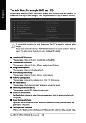
... This setup page is the System auto detect Temperature, voltage, fan, speed. „ MB Intelligent Tweaker(M.I .T.) ESC: Quit F8: Q-Flash Load Fail-Safe Defaults Load Optimized Defaults Set Supervisor Password Set User Password Save & Exit Setup Exit Without Saving KLJI: Select Item F10: Save & Exit Setup Time, Date, Hard Disk Type... GA-8I915GV-MF/GA-8I915GVM Motherboard - 30 - If you can't find the setting you want, please press "Ctrl+F1" to accept or enter the sub-menu. Use arrow keys to...
... This setup page is the System auto detect Temperature, voltage, fan, speed. „ MB Intelligent Tweaker(M.I .T.) ESC: Quit F8: Q-Flash Load Fail-Safe Defaults Load Optimized Defaults Set Supervisor Password Set User Password Save & Exit Setup Exit Without Saving KLJI: Select Item F10: Save & Exit Setup Time, Date, Hard Disk Type... GA-8I915GV-MF/GA-8I915GVM Motherboard - 30 - If you can't find the setting you want, please press "Ctrl+F1" to accept or enter the sub-menu. Use arrow keys to...
Manual
Page 32
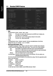
... can manually input the correct settings Access Mode Use this if no IDE devices are : CHS/LBA/Large/Auto(default:Auto) Hard drive information should be labeled on the outside drive casing. English 2-1 Standard CMOS Features Date (mm:dd:yy) Time (hh:mm:ss) CMOS Setup Utility-Copyright (C) 1984-2004 Award Software Standard CMOS Features Thu, Apr 29 2004 22:31:24 Item Help Menu Level` ` IDE Channel 0 Master ` IDE Channel 0 Slave ` IDE Channel 2 Master ` IDE Channel 2 Slave ` IDE Channel 3 Master ` IDE Channel 3 Slave Drive A Drive B Floppy 3 Mode...
... can manually input the correct settings Access Mode Use this if no IDE devices are : CHS/LBA/Large/Auto(default:Auto) Hard drive information should be labeled on the outside drive casing. English 2-1 Standard CMOS Features Date (mm:dd:yy) Time (hh:mm:ss) CMOS Setup Utility-Copyright (C) 1984-2004 Award Software Standard CMOS Features Thu, Apr 29 2004 22:31:24 Item Help Menu Level` ` IDE Channel 0 Master ` IDE Channel 0 Slave ` IDE Channel 2 Master ` IDE Channel 2 Slave ` IDE Channel 3 Master ` IDE Channel 3 Slave Drive A Drive B Floppy 3 Mode...
Manual
Page 34
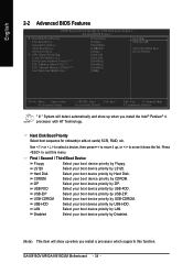
.... USB-HDD Select your boot device priority by LAN. Use < > or < > to select a device, then press to move it up when you install a processor which supports this menu. LS120 Select your boot device priority by ZIP. Disabled Select your boot device priority by LS120. to 3 No-Execute Memory Protect (Note) CPU Enhanced Halt (C1E) (Note) CPU Thermal Monitor 2(TM2) (Note) On-Chip Frame Buffer Size [Press Enter] [Floppy] [Hard Disk] [CDROM] [Setup] [Enabled] [Enabled] [Disabled] [Disabled] [Disabled] [8MB] Item Help Menu Level` Select Hard Disk Boot Device...
.... USB-HDD Select your boot device priority by LAN. Use < > or < > to select a device, then press to move it up when you install a processor which supports this menu. LS120 Select your boot device priority by ZIP. Disabled Select your boot device priority by LS120. to 3 No-Execute Memory Protect (Note) CPU Enhanced Halt (C1E) (Note) CPU Thermal Monitor 2(TM2) (Note) On-Chip Frame Buffer Size [Press Enter] [Floppy] [Hard Disk] [CDROM] [Setup] [Enabled] [Enabled] [Disabled] [Disabled] [Disabled] [8MB] Item Help Menu Level` Select Hard Disk Boot Device...
Manual
Page 36
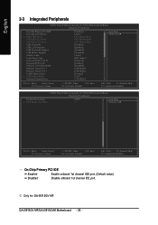
...-8I915GV-MF. English 2-3 Integrated Peripherals CMOS Setup Utility-Copyright (C) 1984-2004 Award Software Integrated Peripherals On-Chip Primary PCI IDE On-Chip SATA Mode x PATA IDE Set to SATA Port 0/2 Set to SATA Port 1/3 Set to USB Controller USB 2.0 Controller USB Keyboard Support USB Mouse Support Azalia Codec Front Panel Type Onboard H/W 1394 1 Onboard H/W LAN Onboard LAN Boot ROM Onboard Serial Port 1 Onboard Serial Port 2 UART Mode Select x UR2 Duplex Mode Onboard Parallel Port [Enabled] [Auto] Ch.1 Master/Slave Ch.2 Master/Slave Ch.3 Master/Slave [Enabled] [Enabled] [Disabled...
...-8I915GV-MF. English 2-3 Integrated Peripherals CMOS Setup Utility-Copyright (C) 1984-2004 Award Software Integrated Peripherals On-Chip Primary PCI IDE On-Chip SATA Mode x PATA IDE Set to SATA Port 0/2 Set to SATA Port 1/3 Set to USB Controller USB 2.0 Controller USB Keyboard Support USB Mouse Support Azalia Codec Front Panel Type Onboard H/W 1394 1 Onboard H/W LAN Onboard LAN Boot ROM Onboard Serial Port 1 Onboard Serial Port 2 UART Mode Select x UR2 Duplex Mode Onboard Parallel Port [Enabled] [Auto] Ch.1 Master/Slave Ch.2 Master/Slave Ch.3 Master/Slave [Enabled] [Enabled] [Disabled...
Manual
Page 43
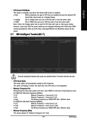
..., the Voltage option can 't boot, clear CMOS to overcome wrong frequency issue. The option will display "Locked" and read only if the CPU ratio is enabled. BIOS Setup Memory Frequency For Wrong frequency may cause your system broken. Auto Set Memory frequency by DRAM SPD data. (Default value) for FSB(Front Side Bus) frequency=533MHz, 3.0 Memory Frequency = Host clock X 3.0. 4.0 Memory Frequency = Host clock X 4.0. However, some 4-pin CPU fan power cables are not designed following Intel 4-Wire fans PWM control specifications. Auto BIOS autodetects the type of CPU fan you use...
..., the Voltage option can 't boot, clear CMOS to overcome wrong frequency issue. The option will display "Locked" and read only if the CPU ratio is enabled. BIOS Setup Memory Frequency For Wrong frequency may cause your system broken. Auto Set Memory frequency by DRAM SPD data. (Default value) for FSB(Front Side Bus) frequency=533MHz, 3.0 Memory Frequency = Host clock X 3.0. 4.0 Memory Frequency = Host clock X 4.0. However, some 4-pin CPU fan power cables are not designed following Intel 4-Wire fans PWM control specifications. Auto BIOS autodetects the type of CPU fan you use...
Manual
Page 45
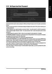
... or any time you try to enter Setup. - 45 - English 2-10 Set Supervisor/User Password CMOS Setup Utility-Copyright (C) 1984-2004 Award Software ` Standard CMOS Features ` Advanced BIOS Features ` Integrated Peripherals ` Power Management Setup ` PnP/PCI ConfigurationEsnter Password: ` PC Health Status ` MB Intelligent Tweaker(M.I.T.) Load Fail-Safe Defaults Load Optimized Defaults Set Supervisor Password Set User Password Save & Exit Setup Exit Without Saving ESC: Quit F8: Q-Flash KLJI: Select Item F10: Save & Exit Setup Change/Set/Disable Password Selecting this function, the...
... or any time you try to enter Setup. - 45 - English 2-10 Set Supervisor/User Password CMOS Setup Utility-Copyright (C) 1984-2004 Award Software ` Standard CMOS Features ` Advanced BIOS Features ` Integrated Peripherals ` Power Management Setup ` PnP/PCI ConfigurationEsnter Password: ` PC Health Status ` MB Intelligent Tweaker(M.I.T.) Load Fail-Safe Defaults Load Optimized Defaults Set Supervisor Password Set User Password Save & Exit Setup Exit Without Saving ESC: Quit F8: Q-Flash KLJI: Select Item F10: Save & Exit Setup Change/Set/Disable Password Selecting this function, the...

Manual
Page 47
... and then list all items defaulted. Please pick the item that recommended to install. After restarting your CD-ROM drive, the driver CD-title will continue to install all the drivers that you want and press "install" followed the item; For USB2.0 driver support under "Device Manager". Insert the driver CD-title that came with your motherboard into your system the "Xpress Install" will auto start and...
... and then list all items defaulted. Please pick the item that recommended to install. After restarting your CD-ROM drive, the driver CD-title will continue to install all the drivers that you want and press "install" followed the item; For USB2.0 driver support under "Device Manager". Insert the driver CD-title that came with your motherboard into your system the "Xpress Install" will auto start and...

Manual
Page 51
... computers such as CPU, memory, graphics card, etc. Download Center Download Center allows users to enabled Gigabyte's unique C.I.A. 2 and M.I .T.'s integration of programs. When the function is disabled, the CPU is a unique feature that allows system hardware information such as providing the most up the PC chassis and short-circuit the "Clear CMOS" pins or the battery on the motherboard to reset the system back to optimize memory performance by the...
... computers such as CPU, memory, graphics card, etc. Download Center Download Center allows users to enabled Gigabyte's unique C.I.A. 2 and M.I .T.'s integration of programs. When the function is disabled, the CPU is a unique feature that allows system hardware information such as providing the most up the PC chassis and short-circuit the "Clear CMOS" pins or the battery on the motherboard to reset the system back to optimize memory performance by the...

Manual
Page 57
... Disable Boot From Main Bios Auto Recovery Enable Halt On Error Disable Copy Main ROM Data to Backup Load Default Settings Save Settings to CMOS Q-Flash Utility Load Main BIOS from Floppy Load Backup BIOS from Floppy Save Main BIOS to Floppy Save Backup BIOS to perform these actions. - 57 - Pressing the buttons mentioned on your keyboards to Floppy Enter : Run :Move ESC:Reset F10:Power Off Dual BIOS utility bar Q-FlashTM utility title bar Action bar Task menu for Q-Flash utility: Contains the names of the following key components. English Entering the Q-FlashTM utility...
... Disable Boot From Main Bios Auto Recovery Enable Halt On Error Disable Copy Main ROM Data to Backup Load Default Settings Save Settings to CMOS Q-Flash Utility Load Main BIOS from Floppy Load Backup BIOS from Floppy Save Main BIOS to Floppy Save Backup BIOS to perform these actions. - 57 - Pressing the buttons mentioned on your keyboards to Floppy Enter : Run :Move ESC:Reset F10:Power Off Dual BIOS utility bar Q-FlashTM utility title bar Action bar Task menu for Q-Flash utility: Contains the names of the following key components. English Entering the Q-FlashTM utility...

Manual
Page 58
... to CMOS Q-Flash Utility Load Main BIOS from Floppy Load Backup BIOS from Floppy" item in the floppy disk. Please confirm again you can begin " section above, you want to save the current BIOS for your motherboard and insert it to your keyboard to move the light bar to "Load Main BIOS from Floppy Save Main BIOS to Floppy Save Backup BIOS to Floppy Enter : Run :Move ESC:Reset F10:Power Off BIOS file in the Q-Flash menu and press Enter button. GA-8I915GV-MF/GA-8I915GVM Motherboard...
... to CMOS Q-Flash Utility Load Main BIOS from Floppy Load Backup BIOS from Floppy" item in the floppy disk. Please confirm again you can begin " section above, you want to save the current BIOS for your motherboard and insert it to your keyboard to move the light bar to "Load Main BIOS from Floppy Save Main BIOS to Floppy Save Backup BIOS to Floppy Enter : Run :Move ESC:Reset F10:Power Off BIOS file in the Q-Flash menu and press Enter button. GA-8I915GV-MF/GA-8I915GVM Motherboard...

Manual
Page 59
... exit Q-Flash. Load Default Settings Save Settings to CMOS Q-Flash Utility Load Main BIOS from Floppy Load Backup BIOS from Floppy Save Main BIOS to Floppy Save Backup BIOS to Floppy Enter : Run :Move ESC:Reset F10:Power Off You can repeat Step 1 to 4 to enter SETUP / Dual BIOS / Q-Flash / F9 For Xpress Recovery 09/23/2003-i875P-6A79BG03C-00 - 59 - Award Modular BIOS v6.00PG, An Energy Star Ally Copyright (C) 1984-2003, Award Software, Inc. Appendix English 3. Press Y button on your keyboard after updating. The...
... exit Q-Flash. Load Default Settings Save Settings to CMOS Q-Flash Utility Load Main BIOS from Floppy Load Backup BIOS from Floppy Save Main BIOS to Floppy Save Backup BIOS to Floppy Enter : Run :Move ESC:Reset F10:Power Off You can repeat Step 1 to 4 to enter SETUP / Dual BIOS / Q-Flash / F9 For Xpress Recovery 09/23/2003-i875P-6A79BG03C-00 - 59 - Award Modular BIOS v6.00PG, An Energy Star Ally Copyright (C) 1984-2003, Award Software, Inc. Appendix English 3. Press Y button on your keyboard after updating. The...
Manual
Page 60
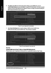
... Disk Type... This part guides users of single-BIOS motherboards how to enter BIOS menu after you are in BIOS menu, move to Load Fail-Safe Defaults item and press Enter to CMOS and exit the BIOS menu. System will reboot after system reboots. The procedure is completed. CMOS Setup Utility-Copyright (C) 1984-2004 Award Software Standard CMOS Features Select Language Advanced BIOS Features Load Fail-Safe Defaults Integrated Peripherals Load Optimized Defaults Power Management Setup Save to load defaults. 7. Press Del to update BIOS using the Q-FlashTM utility. GA...
... Disk Type... This part guides users of single-BIOS motherboards how to enter BIOS menu after you are in BIOS menu, move to Load Fail-Safe Defaults item and press Enter to CMOS and exit the BIOS menu. System will reboot after system reboots. The procedure is completed. CMOS Setup Utility-Copyright (C) 1984-2004 Award Software Standard CMOS Features Select Language Advanced BIOS Features Load Fail-Safe Defaults Integrated Peripherals Load Optimized Defaults Power Management Setup Save to load defaults. 7. Press Del to update BIOS using the Q-FlashTM utility. GA...
Manual
Page 63
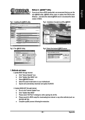
... "Internet Update" icon b. Click "Update New BIOS" icon c. Select the exact model name on your motherboard e. Click "Update New BIOS" c. II. Complete update process following the instruction. - 63 - Fig 1. Appendix English Method 2 : @BIOSTM Utility If you do not have a DOS startup disk, we recommend that you use the new @BIOS utility. @BIOS allows users to download the latest version of BIOS. The @BIOS Utility Click " " Click "Update New BIOS" Fig 4. Please select "All Files...
... "Internet Update" icon b. Click "Update New BIOS" icon c. Select the exact model name on your motherboard e. Click "Update New BIOS" c. II. Complete update process following the instruction. - 63 - Fig 1. Appendix English Method 2 : @BIOSTM Utility If you do not have a DOS startup disk, we recommend that you use the new @BIOS utility. @BIOS allows users to download the latest version of BIOS. The @BIOS Utility Click " " Click "Update New BIOS" Fig 4. Please select "All Files...

Manual
Page 69
... object to connect the positive and negative pins in the battery holder to load Fail-Safe Defaults (Or Load BIOS Defaults) after updating BIOS? Answer: If your board doesn't have such jumper, you don't need to clear CMOS. Save changes and reboot the system. Answer: Some advanced options are using is still on. Turn off the on-board battery to leak voltage to change another speaker with an internal amplifier. Take out the battery gently and...
... object to connect the positive and negative pins in the battery holder to load Fail-Safe Defaults (Or Load BIOS Defaults) after updating BIOS? Answer: If your board doesn't have such jumper, you don't need to clear CMOS. Save changes and reboot the system. Answer: Some advanced options are using is still on. Turn off the on-board battery to leak voltage to change another speaker with an internal amplifier. Take out the battery gently and...

Manual
Page 70
... not connect any cable that is your own cables to case. Question 8: Sometimes I use the IDE 2? The situations might differ from case to it from computer after system boots up. gate A20 failure 7 beeps Processor exception interrupt error 8 beeps Display memory read/write failure 9 beeps ROM checksum error 10 beeps CMOS shutdown register read/write error 11 beeps Cache memory bad AWARD BIOS Beep Codes 1 short: System boots successfully 2 short: CMOS setting error 1 long 1 short: DRAM or M/B error 1 long 2 short: Monitor or display card error 1 long 3 short: Keyboard error 1 long...
... not connect any cable that is your own cables to case. Question 8: Sometimes I use the IDE 2? The situations might differ from case to it from computer after system boots up. gate A20 failure 7 beeps Processor exception interrupt error 8 beeps Display memory read/write failure 9 beeps ROM checksum error 10 beeps CMOS shutdown register read/write error 11 beeps Cache memory bad AWARD BIOS Beep Codes 1 short: System boots successfully 2 short: CMOS setting error 1 long 1 short: DRAM or M/B error 1 long 2 short: Monitor or display card error 1 long 3 short: Keyboard error 1 long...


