Manual
Page 1
GA-8I915GV-MF/ GA-8I915GVM Intel® Pentium® 4 LGA775 Processor Motherboard User's Manual Rev. 1202 12ME-I915GVMF-1202 * The WEEE marking on the product indicates this product must not be disposed of with user's other household waste and must be handed over to a designated collection point for the recycling of waste electrical and electronic equipment!! * The WEEE marking applies only in European Union's member states.
GA-8I915GV-MF/ GA-8I915GVM Intel® Pentium® 4 LGA775 Processor Motherboard User's Manual Rev. 1202 12ME-I915GVMF-1202 * The WEEE marking on the product indicates this product must not be disposed of with user's other household waste and must be handed over to a designated collection point for the recycling of waste electrical and electronic equipment!! * The WEEE marking applies only in European Union's member states.
Manual
Page 2
Motherboard GA-8I915GV-MF/GA-8I915GVM Nov. 24, 2004 Motherboard GA-8I915GV-MF/ GA-8I915GVM Nov. 24, 2004
Motherboard GA-8I915GV-MF/GA-8I915GVM Nov. 24, 2004 Motherboard GA-8I915GV-MF/ GA-8I915GVM Nov. 24, 2004
Manual
Page 4
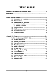
Table of Content GA-8I915GV-MF/GA-8I915GVM Motherboard Layout 6 Block Diagram ...7 Chapter 1 Hardware Installation 9 1-1 Considerations Prior to Installation 9 1-2 Feature Summary 10 1-3 Installation of the CPU and Heatsink 12 1-3-1 Installation of the ...
Table of Content GA-8I915GV-MF/GA-8I915GVM Motherboard Layout 6 Block Diagram ...7 Chapter 1 Hardware Installation 9 1-1 Considerations Prior to Installation 9 1-2 Feature Summary 10 1-3 Installation of the CPU and Heatsink 12 1-3-1 Installation of the ...
Manual
Page 6
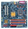
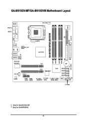
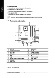
Only for GA-8I915GV-MF. GA-8I915GV-MF/GA-8I915GVM Motherboard Layout IT8712 KB_MS SPDIF_O SPDIF_I CPU_FAN SYS_FAN IR ATX GA-8I915GV-MF/GA-8I915GVM DDR1 DDR2 VGA LPT R_USB ATX_12V LGA775 USB LAN AZALIA_FP AUDIO1 AUDIO2 RTL8110S RTL8100C Intel 915GV PCI1 DDR3 DDR4 IDE FDD BAT CLR_CMOS CD_IN CODEC PCIE_1 COMA COMB PCI2 TSB43AB23 ICH6 F2_1394 F1_1394 F_USB1 F_USB2 SATA3 SATA2 SATA1 SATA0 BIOS PWR_LED F_PANEL Only for GA-8I915GVM. - 6 -
Only for GA-8I915GV-MF. GA-8I915GV-MF/GA-8I915GVM Motherboard Layout IT8712 KB_MS SPDIF_O SPDIF_I CPU_FAN SYS_FAN IR ATX GA-8I915GV-MF/GA-8I915GVM DDR1 DDR2 VGA LPT R_USB ATX_12V LGA775 USB LAN AZALIA_FP AUDIO1 AUDIO2 RTL8110S RTL8100C Intel 915GV PCI1 DDR3 DDR4 IDE FDD BAT CLR_CMOS CD_IN CODEC PCIE_1 COMA COMB PCI2 TSB43AB23 ICH6 F2_1394 F1_1394 F_USB1 F_USB2 SATA3 SATA2 SATA1 SATA0 BIOS PWR_LED F_PANEL Only for GA-8I915GVM. - 6 -
Manual
Page 7
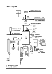
Only for GA-8I915GV-MF. Block Diagram VGA LGA775 Processor CPUCLK+/-(200/133MHz) 1 PCIExpress x 1Ports PCI-ECLK(100MHz) PCI Express x1 Bus PCI Bus RTL 8110S RTL 8100C TSB43AB23 RJ45 3 .../2 KB/Mouse Center/Subwoofer Speaker Out Surround Speaker Out Side Speaker Out MIC Line-Out Line-In SPDIF In SPDIF Out PCICLK (33MHz) Only for GA-8I915GVM. - 7 -
Only for GA-8I915GV-MF. Block Diagram VGA LGA775 Processor CPUCLK+/-(200/133MHz) 1 PCIExpress x 1Ports PCI-ECLK(100MHz) PCI Express x1 Bus PCI Bus RTL 8110S RTL 8100C TSB43AB23 RJ45 3 .../2 KB/Mouse Center/Subwoofer Speaker Out Surround Speaker Out Side Speaker Out MIC Line-Out Line-In SPDIF In SPDIF Out PCICLK (33MHz) Only for GA-8I915GVM. - 7 -
Manual
Page 10
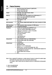
... memory size will instead be shown as 3.xxGB memory during system startup. Only for system usage and therefore the actual memory size is reserved for GA-8I915GVM. English 1-2 Feature Summary CPU Chipset Memory Slots IDE Connections FDD Connections Onboard SATA Peripherals Onboard LAN Onboard Audio Š Supports the latest Intel®... Realtek 8100C chip (10/100 Mbit) Š 1 RJ 45 port Š ALC880 CODEC Š High Definition Audio Š Supports 2 / 4 / 6 / 8 channel audio Š Supports Line In ; GA-8I915GV-MF/GA-8I915GVM Motherboard - 10 - Only for GA-8I915GV-MF.
... memory size will instead be shown as 3.xxGB memory during system startup. Only for system usage and therefore the actual memory size is reserved for GA-8I915GVM. English 1-2 Feature Summary CPU Chipset Memory Slots IDE Connections FDD Connections Onboard SATA Peripherals Onboard LAN Onboard Audio Š Supports the latest Intel®... Realtek 8100C chip (10/100 Mbit) Š 1 RJ 45 port Š ALC880 CODEC Š High Definition Audio Š Supports 2 / 4 / 6 / 8 channel audio Š Supports Line In ; GA-8I915GV-MF/GA-8I915GVM Motherboard - 10 - Only for GA-8I915GV-MF.
Manual
Page 12
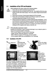
... position. (Grasping the CPU firmly between the CPU and heatsink. 4. Fig. 4 Once the CPU is installed on the CPU socket to the CPU during installation.) GA-8I915GV-MF/GA-8I915GVM Motherboard - 12 - Fig. 2 Remove the plastic covering on the edge of Hyper-Threading Technology for your thumb and forefinger, carefully place it enabled -
... position. (Grasping the CPU firmly between the CPU and heatsink. 4. Fig. 4 Once the CPU is installed on the CPU socket to the CPU during installation.) GA-8I915GV-MF/GA-8I915GVM Motherboard - 12 - Fig. 2 Remove the plastic covering on the edge of Hyper-Threading Technology for your thumb and forefinger, carefully place it enabled -
Manual
Page 14
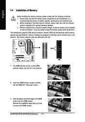
... it down. 3. English 1-4 Installation of the DIMM slots to lock the DIMM module. Memory modules are unable to insert the module, please switch the direction. GA-8I915GV-MF/GA-8I915GVM Motherboard - 14 - Notch DDR 1. The motherboard supports DDR memory modules, whereby BIOS will automatically detect memory capacity and specifications. Please make sure that the...
... it down. 3. English 1-4 Installation of the DIMM slots to lock the DIMM module. Memory modules are unable to insert the module, please switch the direction. GA-8I915GV-MF/GA-8I915GVM Motherboard - 14 - Notch DDR 1. The motherboard supports DDR memory modules, whereby BIOS will automatically detect memory capacity and specifications. Please make sure that the...
Manual
Page 15
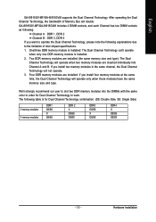
... the same time, the Dual Channel Technology will operate only when those modules have the same memory size and type. English GA-8I915GV-MF/GA-8I915GVM supports the Dual Channel Technology. If you want to operate the Dual Channel Technology, please note the following table is ...installed. 2. Hardware Installation We'll strongly recommend our user to slot two DDR memory modules into Channel A and B. GA-8I915GV-MF/GA-8I915GVM includes 4 DIMM sockets, and each Channel has two DIMM sockets as following: Channel A : DDR 1, DDR 2 Channel B : DDR 3, DDR...
... the same time, the Dual Channel Technology will operate only when those modules have the same memory size and type. English GA-8I915GV-MF/GA-8I915GVM supports the Dual Channel Technology. If you want to operate the Dual Channel Technology, please note the following table is ...installed. 2. Hardware Installation We'll strongly recommend our user to slot two DDR memory modules into Channel A and B. GA-8I915GV-MF/GA-8I915GVM includes 4 DIMM sockets, and each Channel has two DIMM sockets as following: Channel A : DDR 1, DDR 2 Channel B : DDR 3, DDR...
Manual
Page 16
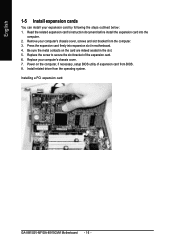
Replace your computer's chassis cover, screws and slot bracket from the computer. 3. Installing a PCI expansion card: GA-8I915GV-MF/GA-8I915GVM Motherboard - 16 - Install related driver from BIOS. 8. Replace the screw to secure the slot bracket of expansion card from the operating system. Remove your ...
Replace your computer's chassis cover, screws and slot bracket from the computer. 3. Installing a PCI expansion card: GA-8I915GV-MF/GA-8I915GVM Motherboard - 16 - Install related driver from BIOS. 8. Replace the screw to secure the slot bracket of expansion card from the operating system. Remove your ...
Manual
Page 17
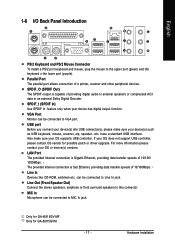
... SPDIF output is capable of a printer, scanner and other peripheral devices. have a standard USB interface. Also make sure your OS supports USB controller. Only for GA-8I915GV-MF. Parallel Port The parallel port allows connection of providing digital audio to external speakers or compressed AC3 data to Line In jack. can be connected...
... SPDIF output is capable of a printer, scanner and other peripheral devices. have a standard USB interface. Also make sure your OS supports USB controller. Only for GA-8I915GV-MF. Parallel Port The parallel port allows connection of providing digital audio to external speakers or compressed AC3 data to Line In jack. can be connected...
Manual
Page 18
Side Speaker Out Connect the side surround speakers to this connector. You can use audio software to this connector. GA-8I915GV-MF/GA-8I915GVM Motherboard - 18 - English Rear Speaker Out Connect the rear surround speakers to this connector. Center/Subwoofer Speaker Out Connect the Center/Subwoofer speakers to ... / SATA2 / SATA3 8) F_PANEL 9) PWR_LED 10) AZALIA_FP 11) CD_IN 12) F_USB1 / F_USB2 13) F1_1394 / F2_1394 14) IR 15) COMA / COMB 16) CLR_CMOS 17) BAT Only for GA-8I915GV-MF.
Side Speaker Out Connect the side surround speakers to this connector. You can use audio software to this connector. GA-8I915GV-MF/GA-8I915GVM Motherboard - 18 - English Rear Speaker Out Connect the rear surround speakers to this connector. Center/Subwoofer Speaker Out Connect the Center/Subwoofer speakers to ... / SATA2 / SATA3 8) F_PANEL 9) PWR_LED 10) AZALIA_FP 11) CD_IN 12) F_USB1 / F_USB2 13) F1_1394 / F2_1394 14) IR 15) COMA / COMB 16) CLR_CMOS 17) BAT Only for GA-8I915GV-MF.
Manual
Page 20
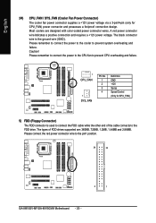
Please remember to connect the power to the cooler to the pin1 position. 34 33 2 1 GA-8I915GV-MF/GA-8I915GVM Motherboard - 20 - The types of the cable connects to the FDD drive. The black connector wire is used to connect the FDD cable while ...
Please remember to connect the power to the cooler to the pin1 position. 34 33 2 1 GA-8I915GV-MF/GA-8I915GVM Motherboard - 20 - The types of the cable connects to the FDD drive. The black connector wire is used to connect the FDD cable while ...
Manual
Page 22
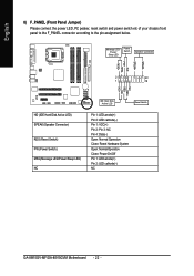
...- Pin 3: NC Pin 4: Data(-) Open: Normal Operation Close: Reset Hardware System Open: Normal Operation Close: Power On/Off Pin 1: LED anode(+) Pin 2: LED cathode(-) NC GA-8I915GV-MF/GA-8I915GVM Motherboard - 22 - Message LED/ Power/ Sleep LED Power Switch Speaker Connector SPEAK-
...- Pin 3: NC Pin 4: Data(-) Open: Normal Operation Close: Reset Hardware System Open: Normal Operation Close: Power On/Off Pin 1: LED anode(+) Pin 2: LED cathode(-) NC GA-8I915GV-MF/GA-8I915GVM Motherboard - 22 - Message LED/ Power/ Sleep LED Power Switch Speaker Connector SPEAK-
Manual
Page 24
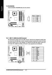
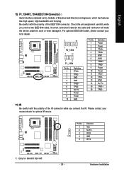
..." is only supported by rear USB ports. Definition 1 Power 2 Power 9 1 3 USB DX- 4 USB Dy- 10 2 5 USB DX+ 6 USB Dy+ 7 GND 8 GND 9 No Pin 10 NC GA-8I915GV-MF/GA-8I915GVM Motherboard - 24 - Check the pin assignment carefully while you connect the front USB cable, incorrect connection between the cable and connector will make the...
..." is only supported by rear USB ports. Definition 1 Power 2 Power 9 1 3 USB DX- 4 USB Dy- 10 2 5 USB DX+ 6 USB Dy+ 7 GND 8 GND 9 No Pin 10 NC GA-8I915GV-MF/GA-8I915GVM Motherboard - 24 - Check the pin assignment carefully while you connect the front USB cable, incorrect connection between the cable and connector will make the...
Manual
Page 25
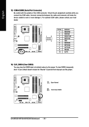
... and hot plug. Check the pin assignment carefully while you connect the IR. Pin No. For optional IEEE1394 cable, please contact your nearest dealer for GA-8I915GV-MF. - 25 - Hardware Installation Definition 1 VCC 2 No Pin 3 IR RX 1 4 GND 5 IR TX Only for optional IR device.
... and hot plug. Check the pin assignment carefully while you connect the IR. Pin No. For optional IEEE1394 cable, please contact your nearest dealer for GA-8I915GV-MF. - 25 - Hardware Installation Definition 1 VCC 2 No Pin 3 IR RX 1 4 GND 5 IR TX Only for optional IR device.
Manual
Page 26
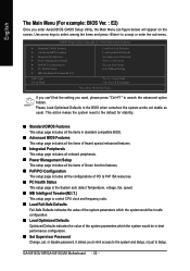
... A/BNRI A/BNo Pin 16) CLR_CMOS (Clear CMOS) You may clear the CMOS data to its default values by this jumper. 1 Open: Normal 1 Short :Clear CMOS GA-8I915GV-MF/GA-8I915GVM Motherboard - 26 - Default doesn't include the "Shunter" to work or even damage it. Check the pin assignment carefully while you connect the COM cable...
... A/BNRI A/BNo Pin 16) CLR_CMOS (Clear CMOS) You may clear the CMOS data to its default values by this jumper. 1 Open: Normal 1 Short :Clear CMOS GA-8I915GV-MF/GA-8I915GVM Motherboard - 26 - Default doesn't include the "Shunter" to work or even damage it. Check the pin assignment carefully while you connect the COM cable...
Manual
Page 30
... system parameters which the system would be in the BIOS when somehow the system works not stable as figure below) will appear on the screen. GA-8I915GV-MF/GA-8I915GVM Motherboard - 30 - Please Load Optimized Defaults in best performance configuration. „ Set Supervisor Password Change, set, or disable password. This action makes the system...
... system parameters which the system would be in the BIOS when somehow the system works not stable as figure below) will appear on the screen. GA-8I915GV-MF/GA-8I915GVM Motherboard - 30 - Please Load Optimized Defaults in best performance configuration. „ Set Supervisor Password Change, set, or disable password. This action makes the system...
Manual
Page 32
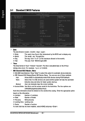
... maximum allowed in . Day The day, from 1 to 31 (or the maximum allowed in the month) Year The year, from Sun to select this information. GA-8I915GV-MF/GA-8I915GVM Motherboard - 32 - English 2-1 Standard CMOS Features Date (mm:dd:yy) Time (hh:mm:ss) CMOS Setup Utility-Copyright (C) 1984-2004 Award Software Standard CMOS...
... maximum allowed in . Day The day, from 1 to 31 (or the maximum allowed in the month) Year The year, from Sun to select this information. GA-8I915GV-MF/GA-8I915GVM Motherboard - 32 - English 2-1 Standard CMOS Features Date (mm:dd:yy) Time (hh:mm:ss) CMOS Setup Utility-Copyright (C) 1984-2004 Award Software Standard CMOS...
Manual
Page 34
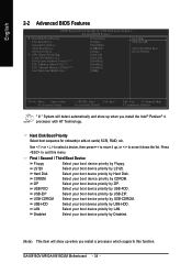
... Help F7: Optimized Defaults " # " System will show up , or to move it down the list. USB-ZIP Select your boot device priority by USB-HDD. GA-8I915GV-MF/GA-8I915GVM Motherboard - 34 - Hard Disk Boot Priority Select boot sequence for onboard(or add-on cards) SCSI, RAID, etc. LS120 Select your boot device priority...
... Help F7: Optimized Defaults " # " System will show up , or to move it down the list. USB-ZIP Select your boot device priority by USB-HDD. GA-8I915GV-MF/GA-8I915GVM Motherboard - 34 - Hard Disk Boot Priority Select boot sequence for onboard(or add-on cards) SCSI, RAID, etc. LS120 Select your boot device priority...