Manual
Page 1
GA-8I915GV-MF/ GA-8I915GVM Intel® Pentium® 4 LGA775 Processor Motherboard User's Manual Rev. 1202 12ME-I915GVMF-1202 * The WEEE marking on the product indicates this product must not be disposed of with user's other household waste and must be handed over to a designated collection point for the recycling of waste electrical and electronic equipment!! * The WEEE marking applies only in European Union's member states.
GA-8I915GV-MF/ GA-8I915GVM Intel® Pentium® 4 LGA775 Processor Motherboard User's Manual Rev. 1202 12ME-I915GVMF-1202 * The WEEE marking on the product indicates this product must not be disposed of with user's other household waste and must be handed over to a designated collection point for the recycling of waste electrical and electronic equipment!! * The WEEE marking applies only in European Union's member states.
Manual
Page 2
Motherboard GA-8I915GV-MF/GA-8I915GVM Nov. 24, 2004 Motherboard GA-8I915GV-MF/ GA-8I915GVM Nov. 24, 2004
Motherboard GA-8I915GV-MF/GA-8I915GVM Nov. 24, 2004 Motherboard GA-8I915GV-MF/ GA-8I915GVM Nov. 24, 2004
Manual
Page 4
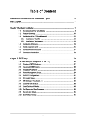
Table of Content GA-8I915GV-MF/GA-8I915GVM Motherboard Layout 6 Block Diagram ...7 Chapter 1 Hardware Installation 9 1-1 Considerations Prior to Installation 9 1-2 Feature Summary 10 1-3 Installation of the CPU and Heatsink 12 1-3-1 Installation of the CPU 12 1-3-2 ...
Table of Content GA-8I915GV-MF/GA-8I915GVM Motherboard Layout 6 Block Diagram ...7 Chapter 1 Hardware Installation 9 1-1 Considerations Prior to Installation 9 1-2 Feature Summary 10 1-3 Installation of the CPU and Heatsink 12 1-3-1 Installation of the CPU 12 1-3-2 ...
Manual
Page 6
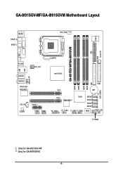
Only for GA-8I915GV-MF. GA-8I915GV-MF/GA-8I915GVM Motherboard Layout IT8712 KB_MS SPDIF_O SPDIF_I CPU_FAN SYS_FAN IR ATX GA-8I915GV-MF/GA-8I915GVM DDR1 DDR2 VGA LPT R_USB ATX_12V LGA775 USB LAN AZALIA_FP AUDIO1 AUDIO2 RTL8110S RTL8100C Intel 915GV PCI1 DDR3 DDR4 IDE FDD BAT CLR_CMOS CD_IN CODEC PCIE_1 COMA COMB PCI2 TSB43AB23 ICH6 F2_1394 F1_1394 F_USB1 F_USB2 SATA3 SATA2 SATA1 SATA0 BIOS PWR_LED F_PANEL Only for GA-8I915GVM. - 6 -
Only for GA-8I915GV-MF. GA-8I915GV-MF/GA-8I915GVM Motherboard Layout IT8712 KB_MS SPDIF_O SPDIF_I CPU_FAN SYS_FAN IR ATX GA-8I915GV-MF/GA-8I915GVM DDR1 DDR2 VGA LPT R_USB ATX_12V LGA775 USB LAN AZALIA_FP AUDIO1 AUDIO2 RTL8110S RTL8100C Intel 915GV PCI1 DDR3 DDR4 IDE FDD BAT CLR_CMOS CD_IN CODEC PCIE_1 COMA COMB PCI2 TSB43AB23 ICH6 F2_1394 F1_1394 F_USB1 F_USB2 SATA3 SATA2 SATA1 SATA0 BIOS PWR_LED F_PANEL Only for GA-8I915GVM. - 6 -
Manual
Page 10
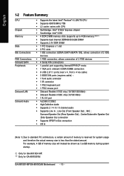
... Line Out (Front Speaker Out) ; Only for system usage and therefore the actual memory size is reserved for GA-8I915GVM. For example, 4 GB of 2 FDD devices Š 4 Serial ATA connections Š 1 parallel port supporting...6 / 8 channel audio Š Supports Line In ; MIC ; Surround Speaker Out (Rear Speaker Out) ; Only for GA-8I915GV-MF. English 1-2 Feature Summary CPU Chipset Memory Slots IDE Connections FDD Connections Onboard SATA Peripherals Onboard LAN Onboard Audio Š ... amount of memory is less than the stated amount. GA-8I915GV-MF/GA-8I915GVM Motherboard - 10 -
... Line Out (Front Speaker Out) ; Only for system usage and therefore the actual memory size is reserved for GA-8I915GVM. For example, 4 GB of 2 FDD devices Š 4 Serial ATA connections Š 1 parallel port supporting...6 / 8 channel audio Š Supports Line In ; MIC ; Surround Speaker Out (Rear Speaker Out) ; Only for GA-8I915GV-MF. English 1-2 Feature Summary CPU Chipset Memory Slots IDE Connections FDD Connections Onboard SATA Peripherals Onboard LAN Onboard Audio Š ... amount of memory is less than the stated amount. GA-8I915GV-MF/GA-8I915GVM Motherboard - 10 -
Manual
Page 12
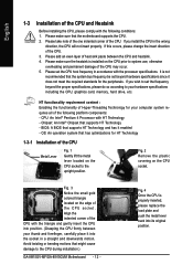
... Remove the plastic covering on the edge of the CPU. It is installed on the CPU socket to the CPU during installation.) GA-8I915GV-MF/GA-8I915GVM Motherboard - 12 - HT functionality requirement content : Enabling the functionality of the CPU with the processor specifications. OS: An operation system ...the required standards for your hardware specifications including the CPU, graphics card, memory, hard drive, etc. BIOS: A BIOS that the motherboard supports the CPU. 2. Fig. 3 Notice the small gold colored triangle located on the CPU socket. Please take note of the...
... Remove the plastic covering on the edge of the CPU. It is installed on the CPU socket to the CPU during installation.) GA-8I915GV-MF/GA-8I915GVM Motherboard - 12 - HT functionality requirement content : Enabling the functionality of the CPU with the processor specifications. OS: An operation system ...the required standards for your hardware specifications including the CPU, graphics card, memory, hard drive, etc. BIOS: A BIOS that the motherboard supports the CPU. 2. Fig. 3 Notice the small gold colored triangle located on the CPU socket. Please take note of the...
Manual
Page 14
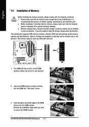
... can be used is switched off to prevent hardware damage. 3. The motherboard supports DDR memory modules, whereby BIOS will automatically detect memory capacity and specifications. Then push it down. 3. Insert the DIMM memory module vertically into the DIMM slot. GA-8I915GV-MF/GA-8I915GVM Motherboard - 14 - Please make sure that they can differ with the following...
... can be used is switched off to prevent hardware damage. 3. The motherboard supports DDR memory modules, whereby BIOS will automatically detect memory capacity and specifications. Then push it down. 3. Insert the DIMM memory module vertically into the DIMM slot. GA-8I915GV-MF/GA-8I915GVM Motherboard - 14 - Please make sure that they can differ with the following...
Manual
Page 16
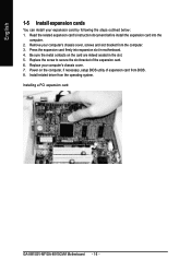
... computer, if necessary, setup BIOS utility of the expansion card. 6. Installing a PCI expansion card: GA-8I915GV-MF/GA-8I915GVM Motherboard - 16 - Replace your computer's chassis cover, screws and slot bracket from the computer. 3. Power on the card are indeed seated in motherboard. 4. Read the related expansion card's instruction document before install the expansion card into expansion...
... computer, if necessary, setup BIOS utility of the expansion card. 6. Installing a PCI expansion card: GA-8I915GV-MF/GA-8I915GVM Motherboard - 16 - Replace your computer's chassis cover, screws and slot bracket from the computer. 3. Power on the card are indeed seated in motherboard. 4. Read the related expansion card's instruction document before install the expansion card into expansion...
Manual
Page 18
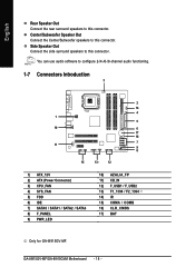
English Rear Speaker Out Connect the rear surround speakers to this connector. GA-8I915GV-MF/GA-8I915GVM Motherboard - 18 - Side Speaker Out Connect the side surround speakers to this connector. You can use audio software to this connector. Center/Subwoofer Speaker Out Connect ... / SATA2 / SATA3 8) F_PANEL 9) PWR_LED 10) AZALIA_FP 11) CD_IN 12) F_USB1 / F_USB2 13) F1_1394 / F2_1394 14) IR 15) COMA / COMB 16) CLR_CMOS 17) BAT Only for GA-8I915GV-MF.
English Rear Speaker Out Connect the rear surround speakers to this connector. GA-8I915GV-MF/GA-8I915GVM Motherboard - 18 - Side Speaker Out Connect the side surround speakers to this connector. You can use audio software to this connector. Center/Subwoofer Speaker Out Connect ... / SATA2 / SATA3 8) F_PANEL 9) PWR_LED 10) AZALIA_FP 11) CD_IN 12) F_USB1 / F_USB2 13) F1_1394 / F2_1394 14) IR 15) COMA / COMB 16) CLR_CMOS 17) BAT Only for GA-8I915GV-MF.
Manual
Page 20
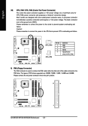
... supported are designed with color-coded power connector wires. Caution! Please remember to connect the power to the cooler to the pin1 position. 34 33 2 1 GA-8I915GV-MF/GA-8I915GVM Motherboard - 20 - Please connect the red power connector wire to prevent system overheating and failure. Most coolers are : 360KB, 720KB, 1.2MB, 1.44MB and 2.88MB. Please...
... supported are designed with color-coded power connector wires. Caution! Please remember to connect the power to the cooler to the pin1 position. 34 33 2 1 GA-8I915GV-MF/GA-8I915GVM Motherboard - 20 - Please connect the red power connector wire to prevent system overheating and failure. Most coolers are : 360KB, 720KB, 1.2MB, 1.44MB and 2.88MB. Please...
Manual
Page 22
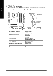
Pin 3: NC Pin 4: Data(-) Open: Normal Operation Close: Reset Hardware System Open: Normal Operation Close: Power On/Off Pin 1: LED anode(+) Pin 2: LED cathode(-) NC GA-8I915GV-MF/GA-8I915GVM Motherboard - 22 - HDHD+ HD (IDE Hard Disk Active LED) SPEAK (Speaker Connector) RES (Reset Switch) PW (Power Switch) MSG(Message LED/Power/Sleep LED) NC IDE...
Pin 3: NC Pin 4: Data(-) Open: Normal Operation Close: Reset Hardware System Open: Normal Operation Close: Power On/Off Pin 1: LED anode(+) Pin 2: LED cathode(-) NC GA-8I915GV-MF/GA-8I915GVM Motherboard - 22 - HDHD+ HD (IDE Hard Disk Active LED) SPEAK (Speaker Connector) RES (Reset Switch) PW (Power Switch) MSG(Message LED/Power/Sleep LED) NC IDE...
Manual
Page 24
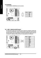
Definition 1 Power 2 Power 9 1 3 USB DX- 4 USB Dy- 10 2 5 USB DX+ 6 USB Dy+ 7 GND 8 GND 9 No Pin 10 NC GA-8I915GV-MF/GA-8I915GVM Motherboard - 24 - Pin No. English 11) CD_IN (CD IN) Connect CD-ROM or DVD-ROM audio out to work or even damage it. Check the pin ...
Definition 1 Power 2 Power 9 1 3 USB DX- 4 USB Dy- 10 2 5 USB DX+ 6 USB Dy+ 7 GND 8 GND 9 No Pin 10 NC GA-8I915GV-MF/GA-8I915GVM Motherboard - 24 - Pin No. English 11) CD_IN (CD IN) Connect CD-ROM or DVD-ROM audio out to work or even damage it. Check the pin ...
Manual
Page 26
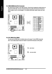
... cable, incorrect connection between the cable and connector will make the device unable to its default values by this jumper. 1 Open: Normal 1 Short :Clear CMOS GA-8I915GV-MF/GA-8I915GVM Motherboard - 26 - Default doesn't include the "Shunter" to prevent from improper use this jumper. English 15) COMA/COMB (Serial Port Connector) Be careful with the...
... cable, incorrect connection between the cable and connector will make the device unable to its default values by this jumper. 1 Open: Normal 1 Short :Clear CMOS GA-8I915GV-MF/GA-8I915GVM Motherboard - 26 - Default doesn't include the "Shunter" to prevent from improper use this jumper. English 15) COMA/COMB (Serial Port Connector) Be careful with the...
Manual
Page 30
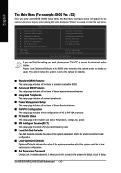
GA-8I915GV-MF/GA-8I915GVM Motherboard - 30 - If you can't find the setting you want, please press "Ctrl+F1" to Setup. Please Load Optimized Defaults in the BIOS when somehow the ...
GA-8I915GV-MF/GA-8I915GVM Motherboard - 30 - If you can't find the setting you want, please press "Ctrl+F1" to Setup. Please Load Optimized Defaults in the BIOS when somehow the ...
Manual
Page 32
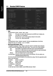
... will skip the automatic detection step and allow for the hard drive. For example, 1 p.m. to Sat, determined by the BIOS and is 13:00:00. GA-8I915GV-MF/GA-8I915GVM Motherboard - 32 -
... will skip the automatic detection step and allow for the hard drive. For example, 1 p.m. to Sat, determined by the BIOS and is 13:00:00. GA-8I915GV-MF/GA-8I915GVM Motherboard - 32 -
Manual
Page 34
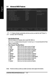
... Boot Device Second Boot Device Third Boot Device Password Check # CPU Hyper-Threading Limit CPUID Max. LS120 Select your boot device priority by Hard Disk. GA-8I915GV-MF/GA-8I915GVM Motherboard - 34 -
... Boot Device Second Boot Device Third Boot Device Password Check # CPU Hyper-Threading Limit CPUID Max. LS120 Select your boot device priority by Hard Disk. GA-8I915GV-MF/GA-8I915GVM Motherboard - 34 -
Manual
Page 36
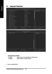
... Help F7: Optimized Defaults On-Chip Primary PCI IDE Enabled Enable onboard 1st channel IDE port. (Default value) Disabled Disable onboard 1st channel IDE port. GA-8I915GV-MF/GA-8I915GVM Motherboard - 36 - Only for GA-8I915GV-MF.
... Help F7: Optimized Defaults On-Chip Primary PCI IDE Enabled Enable onboard 1st channel IDE port. (Default value) Disabled Disable onboard 1st channel IDE port. GA-8I915GV-MF/GA-8I915GVM Motherboard - 36 - Only for GA-8I915GV-MF.
Manual
Page 38
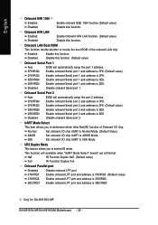
...this function. Enable onboard Serial port 2 and address is 3BC/IRQ7. Set onboard I/O chip UART to ASKIR Mode. Only for GA-8I915GV-MF. Onboard LAN Boot ROM This function decide whether to invoke the boot ROM of Onboard I /O chip UART to IrDA ... and address is 3E8. Disabled Disable onboard Serial port 1. Half IR Function Duplex Half. (Default value) Full IR Function Duplex Full. GA-8I915GV-MF/GA-8I915GVM Motherboard - 38 - Onboard Parallel port Disabled Disable onboard LPT port. 378/IRQ7 Enable onboard LPT port and address is 378/IRQ7. (Default ...
...this function. Enable onboard Serial port 2 and address is 3BC/IRQ7. Set onboard I/O chip UART to ASKIR Mode. Only for GA-8I915GV-MF. Onboard LAN Boot ROM This function decide whether to invoke the boot ROM of Onboard I /O chip UART to IrDA ... and address is 3E8. Disabled Disable onboard Serial port 1. Half IR Function Duplex Half. (Default value) Full IR Function Duplex Full. GA-8I915GV-MF/GA-8I915GVM Motherboard - 38 - Onboard Parallel port Disabled Disable onboard LPT port. 378/IRQ7 Enable onboard LPT port and address is 378/IRQ7. (Default ...
Manual
Page 40
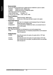
... 5 characters) and press Enter to set the Keyboard Power On Password. Enter Input password (from 1 to 5 characters to set the Keyboard Power On password. GA-8I915GV-MF/GA-8I915GVM Motherboard - 40 - Disabled Enabled Disable this function. (Default value) Double Click Double click on PS/2 mouse left button to power on system. English Resume by Alarm...
... 5 characters) and press Enter to set the Keyboard Power On Password. Enter Input password (from 1 to 5 characters to set the Keyboard Power On password. GA-8I915GV-MF/GA-8I915GVM Motherboard - 40 - Disabled Enabled Disable this function. (Default value) Double Click Double click on PS/2 mouse left button to power on system. English Resume by Alarm...
Manual
Page 42
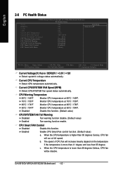
... CPU temperature is more than 41 degree and less than 40 degrees Celsius, CPU fan willbe disable. Enable CPU Smart Fan control function. (Default value) a. GA-8I915GV-MF/GA-8I915GVM Motherboard - 42 - English 2-6 PC Health Status CMOS Setup Utility-Copyright (C) 1984-2004 Award Software PC Health Status Vcore DDR25V +3.3V +12V Current CPU Temperature Current...
... CPU temperature is more than 41 degree and less than 40 degrees Celsius, CPU fan willbe disable. Enable CPU Smart Fan control function. (Default value) a. GA-8I915GV-MF/GA-8I915GVM Motherboard - 42 - English 2-6 PC Health Status CMOS Setup Utility-Copyright (C) 1984-2004 Award Software PC Health Status Vcore DDR25V +3.3V +12V Current CPU Temperature Current...


