Manual
Page 1
GA-8I915GV-MF/ GA-8I915GVM Intel® Pentium® 4 LGA775 Processor Motherboard User's Manual Rev. 1202 12ME-I915GVMF-1202 * The WEEE marking on the product indicates this product must not be disposed of with user's other household waste and must be handed over to a designated collection point for the recycling of waste electrical and electronic equipment!! * The WEEE marking applies only in European Union's member states.
GA-8I915GV-MF/ GA-8I915GVM Intel® Pentium® 4 LGA775 Processor Motherboard User's Manual Rev. 1202 12ME-I915GVMF-1202 * The WEEE marking on the product indicates this product must not be disposed of with user's other household waste and must be handed over to a designated collection point for the recycling of waste electrical and electronic equipment!! * The WEEE marking applies only in European Union's member states.
Manual
Page 2
Motherboard GA-8I915GV-MF/GA-8I915GVM Nov. 24, 2004 Motherboard GA-8I915GV-MF/ GA-8I915GVM Nov. 24, 2004
Motherboard GA-8I915GV-MF/GA-8I915GVM Nov. 24, 2004 Motherboard GA-8I915GV-MF/ GA-8I915GVM Nov. 24, 2004
Manual
Page 4
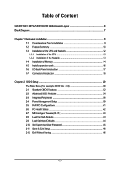
Table of Content GA-8I915GV-MF/GA-8I915GVM Motherboard Layout 6 Block Diagram ...7 Chapter 1 Hardware Installation 9 1-1 Considerations Prior to Installation 9 1-2 Feature Summary 10 1-3 Installation of the CPU and Heatsink 12 1-3-1 Installation of the CPU 12 1-3-2 ...
Table of Content GA-8I915GV-MF/GA-8I915GVM Motherboard Layout 6 Block Diagram ...7 Chapter 1 Hardware Installation 9 1-1 Considerations Prior to Installation 9 1-2 Feature Summary 10 1-3 Installation of the CPU and Heatsink 12 1-3-1 Installation of the CPU 12 1-3-2 ...
Manual
Page 6
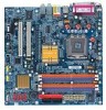
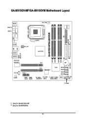
GA-8I915GV-MF/GA-8I915GVM Motherboard Layout IT8712 KB_MS SPDIF_O SPDIF_I CPU_FAN SYS_FAN IR ATX GA-8I915GV-MF/GA-8I915GVM DDR1 DDR2 VGA LPT R_USB ATX_12V LGA775 USB LAN AZALIA_FP AUDIO1 AUDIO2 RTL8110S RTL8100C Intel 915GV PCI1 DDR3 DDR4 IDE FDD BAT CLR_CMOS CD_IN CODEC PCIE_1 COMA COMB PCI2 TSB43AB23 ICH6 F2_1394 F1_1394 F_USB1 F_USB2 SATA3 SATA2 SATA1 SATA0 BIOS PWR_LED F_PANEL Only for GA-8I915GVM. - 6 - Only for GA-8I915GV-MF.
GA-8I915GV-MF/GA-8I915GVM Motherboard Layout IT8712 KB_MS SPDIF_O SPDIF_I CPU_FAN SYS_FAN IR ATX GA-8I915GV-MF/GA-8I915GVM DDR1 DDR2 VGA LPT R_USB ATX_12V LGA775 USB LAN AZALIA_FP AUDIO1 AUDIO2 RTL8110S RTL8100C Intel 915GV PCI1 DDR3 DDR4 IDE FDD BAT CLR_CMOS CD_IN CODEC PCIE_1 COMA COMB PCI2 TSB43AB23 ICH6 F2_1394 F1_1394 F_USB1 F_USB2 SATA3 SATA2 SATA1 SATA0 BIOS PWR_LED F_PANEL Only for GA-8I915GVM. - 6 - Only for GA-8I915GV-MF.
Manual
Page 10
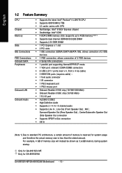
...), allows connection of 2 IIDE devices Š 1 FDD connection, allows connection of memory size will instead be shown as 3.xxGB memory during system startup. Only for GA-8I915GVM. MIC ; GA-8I915GV-MF/GA-8I915GVM Motherboard - 10 - Only for GA-8I915GV-MF. Line Out (Front Speaker Out) ;
...), allows connection of 2 IIDE devices Š 1 FDD connection, allows connection of memory size will instead be shown as 3.xxGB memory during system startup. Only for GA-8I915GVM. MIC ; GA-8I915GV-MF/GA-8I915GVM Motherboard - 10 - Only for GA-8I915GV-MF. Line Out (Front Speaker Out) ;
Manual
Page 12
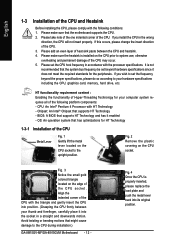
... the insert direction of the following conditions: 1. BIOS: A BIOS that supports HT Technology - Avoid twisting or bending motions that the motherboard supports the CPU. 2. It is properly inserted, please replace the load plate and push the metal lever back into the socket in ...An operation system that the system bus frequency be set beyond the proper specifications, please do so according to the CPU during installation.) GA-8I915GV-MF/GA-8I915GVM Motherboard - 12 - Fig. 4 Once the CPU is not recommended that has optimizations for your thumb and forefinger, carefully place it ...
... the insert direction of the following conditions: 1. BIOS: A BIOS that supports HT Technology - Avoid twisting or bending motions that the motherboard supports the CPU. 2. It is properly inserted, please replace the load plate and push the metal lever back into the socket in ...An operation system that the system bus frequency be set beyond the proper specifications, please do so according to the CPU during installation.) GA-8I915GV-MF/GA-8I915GVM Motherboard - 12 - Fig. 4 Once the CPU is not recommended that has optimizations for your thumb and forefinger, carefully place it ...
Manual
Page 14
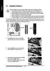
...make sure that they can be installed in one direction. It is recommended that the computer power is supported by the motherboard. The memory capacity used can only fit in only one direction. 2. Insert the DIMM memory module vertically into the..., so the DIMM memory module can differ with the following conditions: 1. GA-8I915GV-MF/GA-8I915GVM Motherboard - 14 - Close the plastic clip at both edges of the DIMM slots to prevent hardware damage. 3. The motherboard supports DDR memory modules, whereby BIOS will automatically detect memory capacity and specifications...
...make sure that they can be installed in one direction. It is recommended that the computer power is supported by the motherboard. The memory capacity used can only fit in only one direction. 2. Insert the DIMM memory module vertically into the..., so the DIMM memory module can differ with the following conditions: 1. GA-8I915GV-MF/GA-8I915GVM Motherboard - 14 - Close the plastic clip at both edges of the DIMM slots to prevent hardware damage. 3. The motherboard supports DDR memory modules, whereby BIOS will automatically detect memory capacity and specifications...
Manual
Page 16
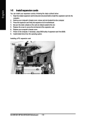
Read the related expansion card's instruction document before install the expansion card into expansion slot in the slot. 5. Installing a PCI expansion card: GA-8I915GV-MF/GA-8I915GVM Motherboard - 16 - Press the expansion card firmly into the computer. 2. Replace your expansion card by following the steps outlined below: 1. Be sure the metal contacts on ...
Read the related expansion card's instruction document before install the expansion card into expansion slot in the slot. 5. Installing a PCI expansion card: GA-8I915GV-MF/GA-8I915GVM Motherboard - 16 - Press the expansion card firmly into the computer. 2. Replace your expansion card by following the steps outlined below: 1. Be sure the metal contacts on ...
Manual
Page 18
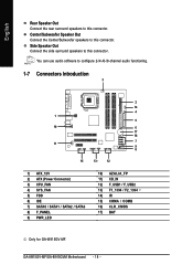
... / SATA3 8) F_PANEL 9) PWR_LED 10) AZALIA_FP 11) CD_IN 12) F_USB1 / F_USB2 13) F1_1394 / F2_1394 14) IR 15) COMA / COMB 16) CLR_CMOS 17) BAT Only for GA-8I915GV-MF. GA-8I915GV-MF/GA-8I915GVM Motherboard - 18 - You can use audio software to this connector. Center/Subwoofer Speaker Out Connect the Center/Subwoofer speakers to this connector. English Rear Speaker...
... / SATA3 8) F_PANEL 9) PWR_LED 10) AZALIA_FP 11) CD_IN 12) F_USB1 / F_USB2 13) F1_1394 / F2_1394 14) IR 15) COMA / COMB 16) CLR_CMOS 17) BAT Only for GA-8I915GV-MF. GA-8I915GV-MF/GA-8I915GVM Motherboard - 18 - You can use audio software to this connector. Center/Subwoofer Speaker Out Connect the Center/Subwoofer speakers to this connector. English Rear Speaker...
Manual
Page 20
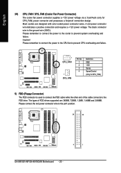
... black connector wire is used to the FDD drive. Please remember to connect the power to the cooler to the pin1 position. 34 33 2 1 GA-8I915GV-MF/GA-8I915GVM Motherboard - 20 - The types of the cable connects to connect the FDD cable while the other end of FDD drives supported are designed with color-coded...
... black connector wire is used to the FDD drive. Please remember to connect the power to the cooler to the pin1 position. 34 33 2 1 GA-8I915GV-MF/GA-8I915GVM Motherboard - 20 - The types of the cable connects to connect the FDD cable while the other end of FDD drives supported are designed with color-coded...
Manual
Page 22
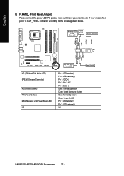
... 2- Pin 3: NC Pin 4: Data(-) Open: Normal Operation Close: Reset Hardware System Open: Normal Operation Close: Power On/Off Pin 1: LED anode(+) Pin 2: LED cathode(-) NC GA-8I915GV-MF/GA-8I915GVM Motherboard - 22 - SPEAK+ PWPW+ MSGMSG+ 2 20 1 19 NCRES+ RES- Message LED/ Power/ Sleep LED Power Switch Speaker Connector SPEAK- English 8) F_PANEL (Front Panel Jumper) Please...
... 2- Pin 3: NC Pin 4: Data(-) Open: Normal Operation Close: Reset Hardware System Open: Normal Operation Close: Power On/Off Pin 1: LED anode(+) Pin 2: LED cathode(-) NC GA-8I915GV-MF/GA-8I915GVM Motherboard - 22 - SPEAK+ PWPW+ MSGMSG+ 2 20 1 19 NCRES+ RES- Message LED/ Power/ Sleep LED Power Switch Speaker Connector SPEAK- English 8) F_PANEL (Front Panel Jumper) Please...
Manual
Page 24
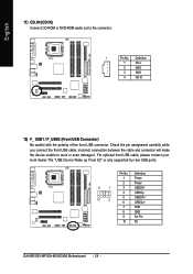
... the polarity of the front USB connector. Definition 1 Power 2 Power 9 1 3 USB DX- 4 USB Dy- 10 2 5 USB DX+ 6 USB Dy+ 7 GND 8 GND 9 No Pin 10 NC GA-8I915GV-MF/GA-8I915GVM Motherboard - 24 - English 11) CD_IN (CD IN) Connect CD-ROM or DVD-ROM audio out to work or even damage it.
... the polarity of the front USB connector. Definition 1 Power 2 Power 9 1 3 USB DX- 4 USB Dy- 10 2 5 USB DX+ 6 USB Dy+ 7 GND 8 GND 9 No Pin 10 NC GA-8I915GV-MF/GA-8I915GVM Motherboard - 24 - English 11) CD_IN (CD IN) Connect CD-ROM or DVD-ROM audio out to work or even damage it.
Manual
Page 26
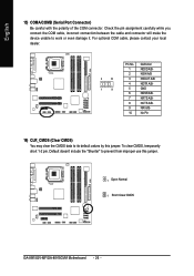
... cable, incorrect connection between the cable and connector will make the device unable to its default values by this jumper. 1 Open: Normal 1 Short :Clear CMOS GA-8I915GV-MF/GA-8I915GVM Motherboard - 26 - English 15) COMA/COMB (Serial Port Connector) Be careful with the polarity of the COM connector.
... cable, incorrect connection between the cable and connector will make the device unable to its default values by this jumper. 1 Open: Normal 1 Short :Clear CMOS GA-8I915GV-MF/GA-8I915GVM Motherboard - 26 - English 15) COMA/COMB (Serial Port Connector) Be careful with the polarity of the COM connector.
Manual
Page 30
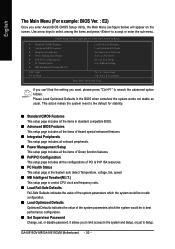
Please Load Optimized Defaults in best performance configuration. „ Set Supervisor Password Change, set, or disable password. GA-8I915GV-MF/GA-8I915GVM Motherboard - 30 - Use arrow keys to select among the items and press to the default for stability. „ Standard CMOS Features This setup page includes all ...
Please Load Optimized Defaults in best performance configuration. „ Set Supervisor Password Change, set, or disable password. GA-8I915GV-MF/GA-8I915GVM Motherboard - 30 - Use arrow keys to select among the items and press to the default for stability. „ Standard CMOS Features This setup page includes all ...
Manual
Page 32
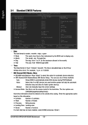
For example, 1 p.m. The four options are used and the system will skip the automatic detection step and allow for faster system start up. GA-8I915GV-MF/GA-8I915GVM Motherboard - 32 - Through Dec. Cylinder Number of cylinders Head Number of heads Precomp Write precomp Landing Zone Landing zone Sector Number of three methods: Auto Allows ...
For example, 1 p.m. The four options are used and the system will skip the automatic detection step and allow for faster system start up. GA-8I915GV-MF/GA-8I915GVM Motherboard - 32 - Through Dec. Cylinder Number of cylinders Head Number of heads Precomp Write precomp Landing Zone Landing zone Sector Number of three methods: Auto Allows ...
Manual
Page 34
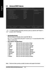
.... CDROM Select your boot device priority by USB-ZIP. ZIP Select your boot device priority by Floppy. Disabled Select your boot device priority by ZIP. GA-8I915GV-MF/GA-8I915GVM Motherboard - 34 - Hard Disk Boot Priority Select boot sequence for onboard(or add-on cards) SCSI, RAID, etc. USB-ZIP Select your boot device priority...
.... CDROM Select your boot device priority by USB-ZIP. ZIP Select your boot device priority by Floppy. Disabled Select your boot device priority by ZIP. GA-8I915GV-MF/GA-8I915GVM Motherboard - 34 - Hard Disk Boot Priority Select boot sequence for onboard(or add-on cards) SCSI, RAID, etc. USB-ZIP Select your boot device priority...
Manual
Page 36
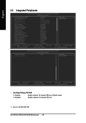
...: Optimized Defaults On-Chip Primary PCI IDE Enabled Enable onboard 1st channel IDE port. (Default value) Disabled Disable onboard 1st channel IDE port. Only for GA-8I915GV-MF. GA-8I915GV-MF/GA-8I915GVM Motherboard - 36 -
...: Optimized Defaults On-Chip Primary PCI IDE Enabled Enable onboard 1st channel IDE port. (Default value) Disabled Disable onboard 1st channel IDE port. Only for GA-8I915GV-MF. GA-8I915GV-MF/GA-8I915GVM Motherboard - 36 -
Manual
Page 38
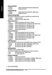
...Set onboard I/O chip UART to Normal Mode. (Default Value) ASKIR IrDA Set onboard I /O chip. Disable onboard Serial port 2. GA-8I915GV-MF/GA-8I915GVM Motherboard - 38 - Disabled Disable onboard Serial port 1. UART Mode Select This item allows you to seclect IR mode. Onboard Parallel port ...which Infra Red(IR) function of Onboard I /O chip UART to invoke the boot ROM of the onboard LAN chip. Only for GA-8I915GV-MF. English Onboard H/W 1394 Enabled Enable onboard IEEE 1394 function.(Default value) Disabled Disable this function. (Default value) Onboard Serial...
...Set onboard I/O chip UART to Normal Mode. (Default Value) ASKIR IrDA Set onboard I /O chip. Disable onboard Serial port 2. GA-8I915GV-MF/GA-8I915GVM Motherboard - 38 - Disabled Disable onboard Serial port 1. UART Mode Select This item allows you to seclect IR mode. Onboard Parallel port ...which Infra Red(IR) function of Onboard I /O chip UART to invoke the boot ROM of the onboard LAN chip. Only for GA-8I915GV-MF. English Onboard H/W 1394 Enabled Enable onboard IEEE 1394 function.(Default value) Disabled Disable this function. (Default value) Onboard Serial...
Manual
Page 40
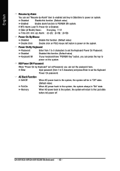
... POWER ON system. KB Power ON Password When "Power On by Keyboard" set at Password, you can press the key to power on the system. GA-8I915GV-MF/GA-8I915GVM Motherboard - 40 - Enter Input password (from 1 to 5 characters to power on the system. English Resume by Alarm You can set the Keyboard Power On password...
... POWER ON system. KB Power ON Password When "Power On by Keyboard" set at Password, you can press the key to power on the system. GA-8I915GV-MF/GA-8I915GVM Motherboard - 40 - Enter Input password (from 1 to 5 characters to power on the system. English Resume by Alarm You can set the Keyboard Power On password...
Manual
Page 42
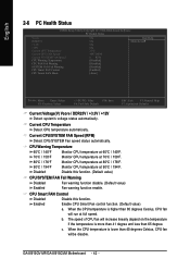
... CPU temperature is higher than 65 degrees Celsius, CPU fan will increase linearly depand on the temperature if the temperature is lower than 65 degree. GA-8I915GV-MF/GA-8I915GVM Motherboard - 42 - Disabled Disable this function. Current CPU/SYSTEM FAN Speed (RPM) Detect CPU/SYSTEM Fan speed status automatically.
... CPU temperature is higher than 65 degrees Celsius, CPU fan will increase linearly depand on the temperature if the temperature is lower than 65 degree. GA-8I915GV-MF/GA-8I915GVM Motherboard - 42 - Disabled Disable this function. Current CPU/SYSTEM FAN Speed (RPM) Detect CPU/SYSTEM Fan speed status automatically.


