Manual
Page 4
...GA-8I915G-MF Motherboard Layout 6 Block Diagram ...7 Chapter 1 Hardware Installation 9 1-1 Considerations Prior to Installation 9 1-2 Feature Summary 10 1-3 Installation of the CPU and Heatsink 12 1-3-1 Installation of the CPU 12 1-3-2 Installation of the Heatsink 13 1-4 Installation of Memory 14 1-5 Install expansion cards 16 1-6 I/O Back Panel Introduction 17 1-7 Connectors Introduction 18 Chapter 2 BIOS... Setup 29 The Main Menu (For example: BIOS Ver. : F2 30 2-1 Standard CMOS Features 32 2-2 Advanced BIOS Features 34 2-3 IntegratedPeripherals ...
...GA-8I915G-MF Motherboard Layout 6 Block Diagram ...7 Chapter 1 Hardware Installation 9 1-1 Considerations Prior to Installation 9 1-2 Feature Summary 10 1-3 Installation of the CPU and Heatsink 12 1-3-1 Installation of the CPU 12 1-3-2 Installation of the Heatsink 13 1-4 Installation of Memory 14 1-5 Install expansion cards 16 1-6 I/O Back Panel Introduction 17 1-7 Connectors Introduction 18 Chapter 2 BIOS... Setup 29 The Main Menu (For example: BIOS Ver. : F2 30 2-1 Standard CMOS Features 32 2-2 Advanced BIOS Features 34 2-3 IntegratedPeripherals ...

Manual
Page 5
Chapter 3 Install Drivers 47 3-1 Install Chipset Drivers 47 3-2 SoftwareApplications 48 3-3 Driver CD Information 48 3-4 Hardware Information 49 3-5 Contact Us ...49 Chapter 4 Appendix 51 4-1 Unique Software Utilities 51 4-1-1 EasyTune 5 Introduction 52 4-1-2 Xpress Recovery2 Introduction 53 4-1-3 Flash BIOS Method Introduction 55 4-1-4 2- / 4- / 6- / 8- Channel Audio Function Introduction 64 4-2 Troubleshooting 68 - 5 -
Chapter 3 Install Drivers 47 3-1 Install Chipset Drivers 47 3-2 SoftwareApplications 48 3-3 Driver CD Information 48 3-4 Hardware Information 49 3-5 Contact Us ...49 Chapter 4 Appendix 51 4-1 Unique Software Utilities 51 4-1-1 EasyTune 5 Introduction 52 4-1-2 Xpress Recovery2 Introduction 53 4-1-3 Flash BIOS Method Introduction 55 4-1-4 2- / 4- / 6- / 8- Channel Audio Function Introduction 64 4-2 Troubleshooting 68 - 5 -
Manual
Page 6
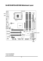
Only for GA-8I915G-MF. GA-8I915G-MF/GA-8I915GM Motherboard Layout IT8712 KB_MS SPDIF_O SPDIF_I CPU_FAN LGA775 SYS_FAN IR ATX VGA LPT R_USB ATX_12V USB LAN AZALIA_FP AUDIO1 AUDIO2 PCIE_16 RTL8110S RTL8100C CD_IN CODEC PCIE_1 COMA COMB GA-8I915G-MF DDR1 DDR2 Intel 915G IDE FDD DDR3 DDR4 PCI1 PCI2 ICH6 TSB43AB23 F2_1394 F1_1394 F_USB1 F_USB2 BAT S_ATA3 S_ATA2 S_ATA1 S_ATA0 CLR_CMOS BIOS PWR_LED F_PANEL Only for GA-8I915GM. - 6 -
Only for GA-8I915G-MF. GA-8I915G-MF/GA-8I915GM Motherboard Layout IT8712 KB_MS SPDIF_O SPDIF_I CPU_FAN LGA775 SYS_FAN IR ATX VGA LPT R_USB ATX_12V USB LAN AZALIA_FP AUDIO1 AUDIO2 PCIE_16 RTL8110S RTL8100C CD_IN CODEC PCIE_1 COMA COMB GA-8I915G-MF DDR1 DDR2 Intel 915G IDE FDD DDR3 DDR4 PCI1 PCI2 ICH6 TSB43AB23 F2_1394 F1_1394 F_USB1 F_USB2 BAT S_ATA3 S_ATA2 S_ATA1 S_ATA0 CLR_CMOS BIOS PWR_LED F_PANEL Only for GA-8I915GM. - 6 -
Manual
Page 7
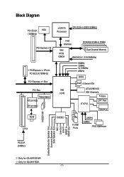
... for GA-8I915G-MF. Block Diagram PCI-ECLK VGA (100MHz) PCI Express x16 1 PCIExpress x 1Ports PCI-ECLK(100MHz) PCI Express x1 Bus PCI Bsu TSB43AB23 RTL8110S RTL8100C RJ45 2 PCI LGA775 Processor CPUCLK+/-(200/133MHz) Host Interface DDR400/333MHz DIMM Intel 915G GMCH Dual Channel Memory GMCHCLK (133/200MHz) 66MHz 33MHz 14.318MHz 48MHz BIOS...
... for GA-8I915G-MF. Block Diagram PCI-ECLK VGA (100MHz) PCI Express x16 1 PCIExpress x 1Ports PCI-ECLK(100MHz) PCI Express x1 Bus PCI Bsu TSB43AB23 RTL8110S RTL8100C RJ45 2 PCI LGA775 Processor CPUCLK+/-(200/133MHz) Host Interface DDR400/333MHz DIMM Intel 915G GMCH Dual Channel Memory GMCHCLK (133/200MHz) 66MHz 33MHz 14.318MHz 48MHz BIOS...
Manual
Page 11
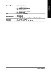
English Hardware Monitor Š System voltage detection Š CPU temperature detection Š CPU / System fan speed detection Š CPU warning temperature Š CPU / System fan failure warning Š CPU smart fan control BIOS Š Use of licensed AWARD BIOS Š Supports Q-Flash Additional Features Š Supports @BIOS Š Supports EasyTune5 (only supports Hardware Monitor function) Overclocking Š Over Clock via BIOS (DDR) Form Factor Š Micro ATX form factor; 24.4 cm x 24.4 cm - 11 - Hardware Installation
English Hardware Monitor Š System voltage detection Š CPU temperature detection Š CPU / System fan speed detection Š CPU warning temperature Š CPU / System fan failure warning Š CPU smart fan control BIOS Š Use of licensed AWARD BIOS Š Supports Q-Flash Additional Features Š Supports @BIOS Š Supports EasyTune5 (only supports Hardware Monitor function) Overclocking Š Over Clock via BIOS (DDR) Form Factor Š Micro ATX form factor; 24.4 cm x 24.4 cm - 11 - Hardware Installation
Manual
Page 12
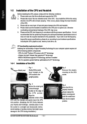
... the one indented corner of the CPU. Please set the frequency beyond hardware specifications since it enabled - If you wish to the CPU during installation.) GA-8I915G-MF/GA-8I915GM Motherboard - 12 - BIOS: A BIOS that might cause damage to set the CPU host frequency in the wrong direction, the CPU will not insert properly.
... the one indented corner of the CPU. Please set the frequency beyond hardware specifications since it enabled - If you wish to the CPU during installation.) GA-8I915G-MF/GA-8I915GM Motherboard - 12 - BIOS: A BIOS that might cause damage to set the CPU host frequency in the wrong direction, the CPU will not insert properly.
Manual
Page 14
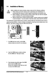
If you wish to prevent hardware damage. 3. Notch DDR 1. Insert the DIMM memory module vertically into the DIMM slot. GA-8I915G-MF/GA-8I915GM Motherboard - 14 - The motherboard supports DDR memory modules, whereby BIOS will automatically detect memory capacity and specifications. The DIMM slot has a notch, so the DIMM memory module can be inserted only in...
If you wish to prevent hardware damage. 3. Notch DDR 1. Insert the DIMM memory module vertically into the DIMM slot. GA-8I915G-MF/GA-8I915GM Motherboard - 14 - The motherboard supports DDR memory modules, whereby BIOS will automatically detect memory capacity and specifications. The DIMM slot has a notch, so the DIMM memory module can be inserted only in...
Manual
Page 16
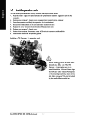
..., screws and slot bracket from the operating system. Be sure the metal contacts on the computer, if necessary, setup BIOS utility of expansion card from BIOS. 8. Replace the screw to the onboard PCI Express x 16 slot and press firmly down on the slot .Make ... English 1-5 Install expansion cards You can install your expansion card by the small white-drawable bar. Install related driver from the computer. 3. GA-8I915G-MF/GA-8I915GM Motherboard - 16 - Power on the card are indeed seated in motherboard. 4. Read the related expansion card's instruction document before install the...
..., screws and slot bracket from the operating system. Be sure the metal contacts on the computer, if necessary, setup BIOS utility of expansion card from BIOS. 8. Replace the screw to the onboard PCI Express x 16 slot and press firmly down on the slot .Make ... English 1-5 Install expansion cards You can install your expansion card by the small white-drawable bar. Install related driver from the computer. 3. GA-8I915G-MF/GA-8I915GM Motherboard - 16 - Power on the card are indeed seated in motherboard. 4. Read the related expansion card's instruction document before install the...
Manual
Page 21
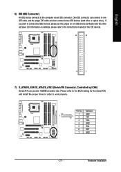
One IDE connector can provide 150MB/s transfer rate. Definition 1 GND 1 7 2 TXP 3 TXN 4 GND 5 RXN 6 RXP 7 GND - 21 - Pin No. Please refer to the BIOS setting for information on settings, please refer to two IDE devices (hard drive or optical drive). Hardware Installation English 6) IDE (IDE Connector) An IDE device ...
One IDE connector can provide 150MB/s transfer rate. Definition 1 GND 1 7 2 TXP 3 TXN 4 GND 5 RXN 6 RXP 7 GND - 21 - Pin No. Please refer to the BIOS setting for information on settings, please refer to two IDE devices (hard drive or optical drive). Hardware Installation English 6) IDE (IDE Connector) An IDE device ...
Manual
Page 23
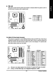
... Installation Definition 1 MPD+ 1 2 MPD- 3 MPD- 10) AZALIA_FP (Front Audio Connector) This connector is the default setting for this connector. To enable AC'97 Audio, from BIOS settings, set Front Panel Type under Integrated Peripherals to indicate whether the system is on/off. It will make the device unable to connect HD...
... Installation Definition 1 MPD+ 1 2 MPD- 3 MPD- 10) AZALIA_FP (Front Audio Connector) This connector is the default setting for this connector. To enable AC'97 Audio, from BIOS settings, set Front Panel Type under Integrated Peripherals to indicate whether the system is on/off. It will make the device unable to connect HD...
Manual
Page 29
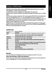
... numeric value or make changes General help window that does not require users to boot to a new BIOS, either Gigabyte's Q-Flash or @BIOS utility can enter the BIOS setup screen by pressing "Ctrl + F1". English Chapter 2 BIOS Setup BIOS (Basic Input and Output System) includes a CMOS SETUP utility which allows user to configure required settings or...
... numeric value or make changes General help window that does not require users to boot to a new BIOS, either Gigabyte's Q-Flash or @BIOS utility can enter the BIOS setup screen by pressing "Ctrl + F1". English Chapter 2 BIOS Setup BIOS (Basic Input and Output System) includes a CMOS SETUP utility which allows user to configure required settings or...
Manual
Page 30
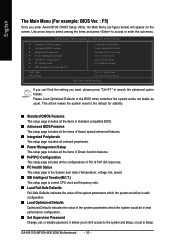
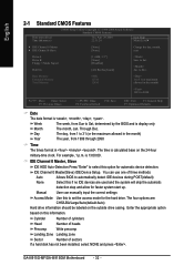
... Set User Password Save & Exit Setup Exit Without Saving KLJI: Select Item F10: Save & Exit Setup Time, Date, Hard Disk Type... GA-8I915G-MF/GA-8I915GM Motherboard - 30 - Use arrow keys to select among the items and press to the default for stability. „ Standard CMOS Features ...This setup page includes all the items in standard compatible BIOS. „ Advanced BIOS Features This setup page includes all the items of Award special enhanced features. „ Integrated Peripherals This setup page includes all ...
... Set User Password Save & Exit Setup Exit Without Saving KLJI: Select Item F10: Save & Exit Setup Time, Date, Hard Disk Type... GA-8I915G-MF/GA-8I915GM Motherboard - 30 - Use arrow keys to select among the items and press to the default for stability. „ Standard CMOS Features ...This setup page includes all the items in standard compatible BIOS. „ Advanced BIOS Features This setup page includes all the items of Award special enhanced features. „ Integrated Peripherals This setup page includes all ...

Manual
Page 31
English „ Set User Password Change, set, or disable password. It allows you to limit access to the system. „ Save & Exit Setup Save CMOS value settings to CMOS and exit setup. „ Exit Without Saving Abandon all CMOS value changes and exit setup. - 31 - BIOS Setup
English „ Set User Password Change, set, or disable password. It allows you to limit access to the system. „ Save & Exit Setup Save CMOS value settings to CMOS and exit setup. „ Exit Without Saving Abandon all CMOS value changes and exit setup. - 31 - BIOS Setup
Manual
Page 32
.... to Dec. Jan. to Sat. GA-8I915G-MF/GA-8I915GM Motherboard - 32 - IDE Channel 0 Master(Slave) IDE Device Setup. Cylinder Number of cylinders Head Number of heads Precomp Write precomp Landing Zone Landing zone Sector Number of three methods: Auto Allows BIOS to 2098 KLJI: Move Enter: Select F5...Total Memory 640K 127M 128M 1 to 31 (or maximum allowed in the month) Year The year, from Sun to Sat, determined by the BIOS and is , , , . You can manually input the correct settings Access Mode Use this to select this information. Week The week, from...
.... to Dec. Jan. to Sat. GA-8I915G-MF/GA-8I915GM Motherboard - 32 - IDE Channel 0 Master(Slave) IDE Device Setup. Cylinder Number of cylinders Head Number of heads Precomp Write precomp Landing Zone Landing zone Sector Number of three methods: Auto Allows BIOS to 2098 KLJI: Move Enter: Select F5...Total Memory 640K 127M 128M 1 to 31 (or maximum allowed in the month) Year The year, from Sun to Sat, determined by the BIOS and is , , , . You can manually input the correct settings Access Mode Use this to select this information. Week The week, from...

Manual
Page 33
... inch AT-type high-density drive; 1.2M byte capacity (3.5 inch when 3 Mode is 3 mode Floppy Drive. it will stop for all other errors. BIOS Setup it will stop for all other errors. (Default value) All, But Diskette The system boot will not stop if an error is determined by...Area) Disabled Normal Floppy Drive. (Default value) Drive A Drive B Both Drive A is present during power up. Base Memory The POST of the BIOS. Floppy 3 Mode Support (for any error that may be stopped. No Errors The system boot will be detected and you All Errors will determine ...
... inch AT-type high-density drive; 1.2M byte capacity (3.5 inch when 3 Mode is 3 mode Floppy Drive. it will stop for all other errors. BIOS Setup it will stop for all other errors. (Default value) All, But Diskette The system boot will not stop if an error is determined by...Area) Disabled Normal Floppy Drive. (Default value) Drive A Drive B Both Drive A is present during power up. Base Memory The POST of the BIOS. Floppy 3 Mode Support (for any error that may be stopped. No Errors The system boot will be detected and you All Errors will determine ...
Manual
Page 34
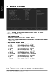
...device priority by LAN. LAN Select your boot device priority by CDROM. USB-FDD Select your boot device priority by USB-ZIP. GA-8I915G-MF/GA-8I915GM Motherboard - 34 - CDROM Select your boot device priority by Floppy. to 3 On-Chip Frame Buffer Size No-Execute ...174; 4 processor with HT Technology. LS120 Select your boot device priority by LS120. English 2-2 Advanced BIOS Features CMOS Setup Utility-Copyright (C) 1984-2004 Award Software Advanced BIOS Features ` Hard Disk Boot Priority First Boot Device Second Boot Device Third Boot Device Password Check #...
...device priority by LAN. LAN Select your boot device priority by CDROM. USB-FDD Select your boot device priority by USB-ZIP. GA-8I915G-MF/GA-8I915GM Motherboard - 34 - CDROM Select your boot device priority by Floppy. to 3 On-Chip Frame Buffer Size No-Execute ...174; 4 processor with HT Technology. LS120 Select your boot device priority by LS120. English 2-2 Advanced BIOS Features CMOS Setup Utility-Copyright (C) 1984-2004 Award Software Advanced BIOS Features ` Hard Disk Boot Priority First Boot Device Second Boot Device Third Boot Device Password Check #...

Manual
Page 35
.... Limit CPUID Max. Disabled Disables No-Execute Memory Protect function. (Default value) CPU Enhanced Halt (C1E) (Note ) Enabled Disabled Enables CPU Enhanced Halt (C1E) function. BIOS Setup On-Chip Frame Buffer Size 1MB Set On-chip frame buffer size to 1MB. 4MB Set On-chip frame buffer size to 4MB. 8MB...
.... Limit CPUID Max. Disabled Disables No-Execute Memory Protect function. (Default value) CPU Enhanced Halt (C1E) (Note ) Enabled Disabled Enables CPU Enhanced Halt (C1E) function. BIOS Setup On-Chip Frame Buffer Size 1MB Set On-chip frame buffer size to 1MB. 4MB Set On-chip frame buffer size to 4MB. 8MB...
Manual
Page 36
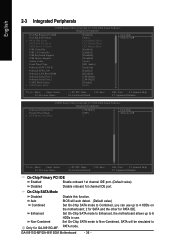
... Motherboard - 36 - On-Chip SATA Mode Disabled Auto Combined Enhanced Non-Combined Disable this function. BIOS will be simulated to 4 HDDs on the motherboard; 2 for SATA and the other for GA-8I915G-MF. Set On-Chip SATA mode to Enhanced, the motherboard allows up to 6 HDDs to use up to Only for PATA IDE...
... Motherboard - 36 - On-Chip SATA Mode Disabled Auto Combined Enhanced Non-Combined Disable this function. BIOS will be simulated to 4 HDDs on the motherboard; 2 for SATA and the other for GA-8I915G-MF. Set On-Chip SATA mode to Enhanced, the motherboard allows up to 6 HDDs to use up to Only for PATA IDE...
Manual
Page 37
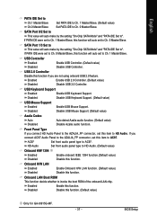
... AZALIA_FP connector, set this function if you connect AC97 Audio Panel to the AZALIA_FP connector, set this function will auto set to HD Audio. BIOS Setup If PATA IDE were set to Ch. 0 Master/Slave, this function will auto set to Ch. 1 Master/Slave, this item to...to AC97. Disabled Disable this function. Onboard H/W LAN Enabled Enable Onboard H/W LAN function. (Default value) Disabled Disable this function. (Default value) Only for GA-8I915G-MF. - 37 - SATA Port 0/2 Set to This value will auto make by the setting "On-Chip SATA Mode" and "PATA IDE Set to HD ...
... AZALIA_FP connector, set this function if you connect AC97 Audio Panel to the AZALIA_FP connector, set this function will auto set to HD Audio. BIOS Setup If PATA IDE were set to Ch. 0 Master/Slave, this function will auto set to Ch. 1 Master/Slave, this item to...to AC97. Disabled Disable this function. Onboard H/W LAN Enabled Enable Onboard H/W LAN function. (Default value) Disabled Disable this function. (Default value) Only for GA-8I915G-MF. - 37 - SATA Port 0/2 Set to This value will auto make by the setting "On-Chip SATA Mode" and "PATA IDE Set to HD ...
Manual
Page 38
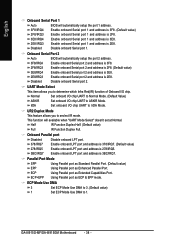
...ASKIR IrDA Set onboard I /O chip UART to IrDA Mode. Using Parallel port as Extended Capabilities Port. English Onboard Serial Port 1 Auto BIOS will available when "UART Mode Select" doesn't set at Normal. UR2 Duplex Mode This feature allows you to seclect IR mode. Onboard ...2 Auto BIOS will automatically setup the port 2 address. 3F8/IRQ4 Enable onboard Serial port 2 and address is 3F8. 2F8/IRQ3 Enable onboard Serial port 2 and address is 2F8. (Default value) 3E8/IRQ4 2E8/IRQ3 Disabled Enable onboard Serial port 2 and address is 2E8. GA-8I915G-MF/GA-8I915GM Motherboard...
...ASKIR IrDA Set onboard I /O chip UART to IrDA Mode. Using Parallel port as Extended Capabilities Port. English Onboard Serial Port 1 Auto BIOS will available when "UART Mode Select" doesn't set at Normal. UR2 Duplex Mode This feature allows you to seclect IR mode. Onboard ...2 Auto BIOS will automatically setup the port 2 address. 3F8/IRQ4 Enable onboard Serial port 2 and address is 3F8. 2F8/IRQ3 Enable onboard Serial port 2 and address is 2F8. (Default value) 3E8/IRQ4 2E8/IRQ3 Disabled Enable onboard Serial port 2 and address is 2E8. GA-8I915G-MF/GA-8I915GM Motherboard...


