Manual
Page 4
...GA-8I865GME-775 Motherboard Layout 7 Block Diagram ...8 Chapter 1 Hardware Installation 9 1-1 Considerations Prior to Installation 9 1-2 Feature Summary 10 1-3 Installation of the CPU and Heatsink 12 1-3-1 Installation of the CPU 12 1-3-2 Installation of the Heatsink 13 1-4 Installation of Memory 14 1-5 Installation of Expansion Cards 15 1-6 I/O Back Panel Introduction 16 1-7 Connectors Introduction 17 Chapter 2 BIOS... Setup 27 The Main Menu (For example: BIOS Ver. : D5 28 2-1 Standard CMOS Features 30 2-2 Advanced BIOS Features 32 2-3 ...
...GA-8I865GME-775 Motherboard Layout 7 Block Diagram ...8 Chapter 1 Hardware Installation 9 1-1 Considerations Prior to Installation 9 1-2 Feature Summary 10 1-3 Installation of the CPU and Heatsink 12 1-3-1 Installation of the CPU 12 1-3-2 Installation of the Heatsink 13 1-4 Installation of Memory 14 1-5 Installation of Expansion Cards 15 1-6 I/O Back Panel Introduction 16 1-7 Connectors Introduction 17 Chapter 2 BIOS... Setup 27 The Main Menu (For example: BIOS Ver. : D5 28 2-1 Standard CMOS Features 30 2-2 Advanced BIOS Features 32 2-3 ...
Manual
Page 5
Chapter 3 Drivers Installation 47 3-1 Install Chipset Drivers 47 3-2 SoftwareApplications 48 3-3 Driver CD Information 48 3-4 Hardware Information 49 3-5 Contact Us ...49 Chapter 4 Appendix 51 4-1 Unique Software Utilities 51 4-1-1 EasyTune 5 Introduction 52 4-1-2 Xpress Recovery2 Introduction 53 4-1-3 Flash BIOS Method Introduction 55 4-1-4 2 / 4 / 6 Channel Audio Function Introduction 64 4-2 Troubleshooting 67 - 5 -
Chapter 3 Drivers Installation 47 3-1 Install Chipset Drivers 47 3-2 SoftwareApplications 48 3-3 Driver CD Information 48 3-4 Hardware Information 49 3-5 Contact Us ...49 Chapter 4 Appendix 51 4-1 Unique Software Utilities 51 4-1-1 EasyTune 5 Introduction 52 4-1-2 Xpress Recovery2 Introduction 53 4-1-3 Flash BIOS Method Introduction 55 4-1-4 2 / 4 / 6 Channel Audio Function Introduction 64 4-2 Troubleshooting 67 - 5 -
Manual
Page 7
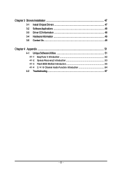
GA-8I865GME-775 Motherboard Layout KB_MS ATX_12V LGA775 CPU_FAN ATX VGA COMA LPT GA-8I865GME-775 DDR1 DDR2 IDE2 IDE1 R_USB USB_LAN IT8712 AUDIO F_AUDIO AGP EP82562G CODEC CD_IN Intel 865G SATA1 PCI1 CI ICH5 SATA0 PCI2 CLR_CMOS PCI3 BAT FDD BIOS F_USB1 PWR_LED SYS _FAN F_PANEL - 7 -
GA-8I865GME-775 Motherboard Layout KB_MS ATX_12V LGA775 CPU_FAN ATX VGA COMA LPT GA-8I865GME-775 DDR1 DDR2 IDE2 IDE1 R_USB USB_LAN IT8712 AUDIO F_AUDIO AGP EP82562G CODEC CD_IN Intel 865G SATA1 PCI1 CI ICH5 SATA0 PCI2 CLR_CMOS PCI3 BAT FDD BIOS F_USB1 PWR_LED SYS _FAN F_PANEL - 7 -
Manual
Page 8
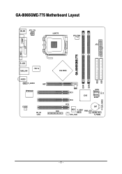
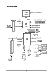
Block Diagram LGA775 Processor CPUCLK+/-(133/200MHz) AGP 8X/4X VGA AGPCLK (66MHz) PCI Bus EP82562G Host Interface DDR 400/333/266MHz DIMM Intel 865G GMCH Dual Channel Memory HCLK (133/200MHz) GMCHCLK (66MHz) 66MHz 33MHz 14.318MHz 48MHz BIOS Intel 2 Serial ATA ICH5 ATA33/66/100 IDE Channels 3 PCI RJ45 AC97 Link AC97 CODEC 6 USB Ports IT8712 Floppy LPT Port COM Port PS/2 KB/Mouse 14.318MHz 33MHz MIC Line-Out Line-In PCICLK (33MHz) - 8 -
Block Diagram LGA775 Processor CPUCLK+/-(133/200MHz) AGP 8X/4X VGA AGPCLK (66MHz) PCI Bus EP82562G Host Interface DDR 400/333/266MHz DIMM Intel 865G GMCH Dual Channel Memory HCLK (133/200MHz) GMCHCLK (66MHz) 66MHz 33MHz 14.318MHz 48MHz BIOS Intel 2 Serial ATA ICH5 ATA33/66/100 IDE Channels 3 PCI RJ45 AC97 Link AC97 CODEC 6 USB Ports IT8712 Floppy LPT Port COM Port PS/2 KB/Mouse 14.318MHz 33MHz MIC Line-Out Line-In PCICLK (33MHz) - 8 -
Manual
Page 11
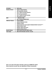
... speed detection Š CPU warning temperature Š CPU / System fan failure warning Š CPU smart fan control BIOS Š 1 3Mbit flash ROM Š Use of licensed AWARD BIOS Additional Features Š Supports @BIOS Š Supports Download Center Š Supports Q-Flash Š Supports EasyTune (only supports Hardware Monitor function)(Note 2) ...version) Form Factor Š Micro ATX form factor; 24.4cm x 21.2cm (Note 1) For further CPU support information, please go to GIGABYTE's website. (Note 2) EasyTune functions may vary depending on different motherboards. - 11 -
... speed detection Š CPU warning temperature Š CPU / System fan failure warning Š CPU smart fan control BIOS Š 1 3Mbit flash ROM Š Use of licensed AWARD BIOS Additional Features Š Supports @BIOS Š Supports Download Center Š Supports Q-Flash Š Supports EasyTune (only supports Hardware Monitor function)(Note 2) ...version) Form Factor Š Micro ATX form factor; 24.4cm x 21.2cm (Note 1) For further CPU support information, please go to GIGABYTE's website. (Note 2) EasyTune functions may vary depending on different motherboards. - 11 -
Manual
Page 12
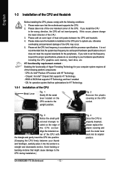
...with the processor specifications. Chipset: An Intel® Chipset that supports HT Technology and has it into its original position. BIOS: A BIOS that supports HT Technology - Align the indented corner of the CPU with the triangle and gently insert the CPU into position...Please make sure that the system bus frequency be set beyond the proper specifications, please do so according to the CPU during installation.) GA-8I865GME-775 Motherboard - 12 - Avoid twisting or bending motions that has optimizations for HT Technology 1-3-1 Installation of the CPU. 3. English 1-3 Installation...
...with the processor specifications. Chipset: An Intel® Chipset that supports HT Technology and has it into its original position. BIOS: A BIOS that supports HT Technology - Align the indented corner of the CPU with the triangle and gently insert the CPU into position...Please make sure that the system bus frequency be set beyond the proper specifications, please do so according to the CPU during installation.) GA-8I865GME-775 Motherboard - 12 - Avoid twisting or bending motions that has optimizations for HT Technology 1-3-1 Installation of the CPU. 3. English 1-3 Installation...
Manual
Page 14
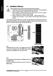
...modules, please make sure that they can only fit in only one direction. Then push it down. DDR memory module Fig. 1 Fig. 2 GA-8I865GME-775 Motherboard - 14 - It is switched off to lock the DIMM module. If you wish to insert the module, please switch the direction. The... motherboard supports DDR memory modules, whereby BIOS will automatically detect memory capacity and specifications. Insert the DIMM memory module vertically into the DIMM socket. Reverse the installation steps when you...
...modules, please make sure that they can only fit in only one direction. Then push it down. DDR memory module Fig. 1 Fig. 2 GA-8I865GME-775 Motherboard - 14 - It is switched off to lock the DIMM module. If you wish to insert the module, please switch the direction. The... motherboard supports DDR memory modules, whereby BIOS will automatically detect memory capacity and specifications. Insert the DIMM memory module vertically into the DIMM socket. Reverse the installation steps when you...
Manual
Page 15
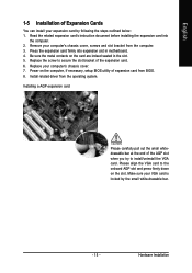
... card firmly into the computer. 2. Replace your VGA card is locked by following the steps outlined below: 1. Install related driver from BIOS. 8. Power on the computer, if necessary, setup BIOS utility of expansion card from the operating system. Read the related expansion card's instruction document before installing the expansion card into expansion...
... card firmly into the computer. 2. Replace your VGA card is locked by following the steps outlined below: 1. Install related driver from BIOS. 8. Power on the computer, if necessary, setup BIOS utility of expansion card from the operating system. Read the related expansion card's instruction document before installing the expansion card into expansion...
Manual
Page 20
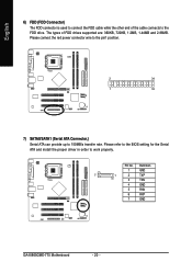
Pin No. Please refer to the BIOS setting for the Serial ATA and install the proper driver in order to 150MB/s transfer rate. The types of the cable connects to the FDD drive. Definition 1 GND 7 1 2 TXP 3 TXN 4 GND 5 RXN 6 RXP 7 GND GA-8I865GME-775 Motherboard - 20 - Please connect the red power connector wire to the...
Pin No. Please refer to the BIOS setting for the Serial ATA and install the proper driver in order to 150MB/s transfer rate. The types of the cable connects to the FDD drive. Definition 1 GND 7 1 2 TXP 3 TXN 4 GND 5 RXN 6 RXP 7 GND GA-8I865GME-775 Motherboard - 20 - Please connect the red power connector wire to the...
Manual
Page 24
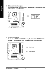
To clear CMOS, temporarily short pins 1-2. You can check the "Case Opened" status in BIOS Setup. 1 Pin No. English 13) CI (Chassis Intrusion, Case Open) This 2-pin connector allows your system to its default values by this header, we do not include a jumper on it. 1 Open: Normal 1 Short: Clear CMOS GA-8I865GME-775 Motherboard - 24 - To prevent improper use of this jumper. Definition 1 Signal 2 GND 14) CLR_CMOS (Clear CMOS) You may clear the CMOS data to detect if the chassis cover is removed.
To clear CMOS, temporarily short pins 1-2. You can check the "Case Opened" status in BIOS Setup. 1 Pin No. English 13) CI (Chassis Intrusion, Case Open) This 2-pin connector allows your system to its default values by this header, we do not include a jumper on it. 1 Open: Normal 1 Short: Clear CMOS GA-8I865GME-775 Motherboard - 24 - To prevent improper use of this jumper. Definition 1 Signal 2 GND 14) CLR_CMOS (Clear CMOS) You may clear the CMOS data to detect if the chassis cover is removed.
Manual
Page 27
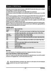
... Menu Item Help Restore the previous CMOS value from CMOS, only for the highlighted item. Quit and not save the current BIOS to a new BIOS, either GIGABYTE's Q-Flash or @BIOS utility can enter the BIOS setup screen by pressing "Ctrl + F1". CONTROL KEYS Enter> Move to activate certain system features. When the power is a Windows...
... Menu Item Help Restore the previous CMOS value from CMOS, only for the highlighted item. Quit and not save the current BIOS to a new BIOS, either GIGABYTE's Q-Flash or @BIOS utility can enter the BIOS setup screen by pressing "Ctrl + F1". CONTROL KEYS Enter> Move to activate certain system features. When the power is a Windows...
Manual
Page 28
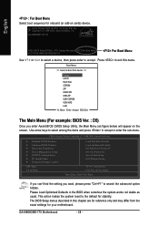
...can't find the setting you enter Award BIOS CMOS Setup Utility, the Main Menu (as usual. The BIOS Setup menus described in the BIOS when somehow the system works not stable as figure below) will appear on cards) device. GA-8I865GME-775 D5 . . . . :BIOS Setup/Q-Flash, : Xpress Recovery2, For Boot... Time, Date, Hard Disk Type... This action makes the system reset to the default for onboard (or add-on the screen. GA-8I865GME-775 Motherboard - 28 - Award Modular BIOS v6.00PG, An Energy Star Ally Copyright (C) 1984-2006, Award Software, Inc. Boot Menu == Select a Boot First device ==...
...can't find the setting you enter Award BIOS CMOS Setup Utility, the Main Menu (as usual. The BIOS Setup menus described in the BIOS when somehow the system works not stable as figure below) will appear on cards) device. GA-8I865GME-775 D5 . . . . :BIOS Setup/Q-Flash, : Xpress Recovery2, For Boot... Time, Date, Hard Disk Type... This action makes the system reset to the default for onboard (or add-on the screen. GA-8I865GME-775 Motherboard - 28 - Award Modular BIOS v6.00PG, An Energy Star Ally Copyright (C) 1984-2006, Award Software, Inc. Boot Menu == Select a Boot First device ==...

Manual
Page 29
.... „ PnP/PCI Configuration This setup page includes all CMOS value changes and exit setup. - 29 - BIOS Setup English „ Standard CMOS Features This setup page includes all the items in standard compatible BIOS. „ Advanced BIOS Features This setup page includes all the items of Award special enhanced features. „ Integrated Peripherals...
.... „ PnP/PCI Configuration This setup page includes all CMOS value changes and exit setup. - 29 - BIOS Setup English „ Standard CMOS Features This setup page includes all the items in standard compatible BIOS. „ Advanced BIOS Features This setup page includes all the items of Award special enhanced features. „ Integrated Peripherals...
Manual
Page 30
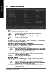
...Date The date format is 13:00:00. to Dec. 1 to 31 (or maximum allowed in . The four options are : Large/Auto(default:Auto) GA-8I865GME-775 Motherboard - 30 - Jan. For example, 1 p.m. IDE Channel 0 Master/Slave ; IDE Channel 1 Master/Slave IDE devices setup. Access Mode Use this...this option for the hard drive. The two options are : CHS/LBA/Large/Auto(default:Auto) Capacity Capacity of three methods: • Auto Allows BIOS to set the access mode for automatic device detection. is , , , . IDE Channel 0 Master/Slave ; Week The week, from 1999 through...
...Date The date format is 13:00:00. to Dec. 1 to 31 (or maximum allowed in . The four options are : Large/Auto(default:Auto) GA-8I865GME-775 Motherboard - 30 - Jan. For example, 1 p.m. IDE Channel 0 Master/Slave ; IDE Channel 1 Master/Slave IDE devices setup. Access Mode Use this...this option for the hard drive. The two options are : CHS/LBA/Large/Auto(default:Auto) Capacity Capacity of three methods: • Auto Allows BIOS to set the access mode for automatic device detection. is , , , . IDE Channel 0 Master/Slave ; Week The week, from 1999 through...
Manual
Page 31
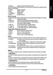
...byte capacity. 2.88M, 3.5" 3.5 inch double-sided drive; 2.88M byte capacity. No Errors The system boot will not stop for a disk error; BIOS Setup This is detected during the POST. None No floppy drive installed 360K, 5.25" 5.25 inch PC-type standard drive; 360K byte capacity. ... 5.25 inch AT-type high-density drive; 1.2M byte capacity (3.5 inch when 3 Mode is 3 mode Floppy Drive. Extended Memory The BIOS determines how much extended memory is determined by POST (Power On Self Test) of currently installed hard drive. Total Memory This item displays the ...
...byte capacity. 2.88M, 3.5" 3.5 inch double-sided drive; 2.88M byte capacity. No Errors The system boot will not stop for a disk error; BIOS Setup This is detected during the POST. None No floppy drive installed 360K, 5.25" 5.25 inch PC-type standard drive; 360K byte capacity. ... 5.25 inch AT-type high-density drive; 1.2M byte capacity (3.5 inch when 3 Mode is 3 mode Floppy Drive. Extended Memory The BIOS determines how much extended memory is determined by POST (Power On Self Test) of currently installed hard drive. Total Memory This item displays the ...
Manual
Page 32
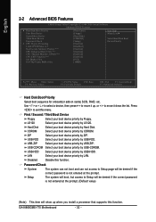
... CMOS Setup Utility-Copyright (C) 1984-2006 Award Software Advanced BIOS Features ` Hard Disk Boot Priority First Boot Device Second Boot Device Third Boot Device Password Check # CPU Hyper-Threading Limit CPUID Max. ZIP USB-FDD ... your boot device priority by USB-CDROM. USB-HDD Select your boot device priority by USB-HDD. LAN Select your boot device priority by LAN. GA-8I865GME-775 Motherboard - 32 - Use < > or < > to select a device, then press to move it up when you install a processor that supports this function. First / Second / Third Boot...
... CMOS Setup Utility-Copyright (C) 1984-2006 Award Software Advanced BIOS Features ` Hard Disk Boot Priority First Boot Device Second Boot Device Third Boot Device Password Check # CPU Hyper-Threading Limit CPUID Max. ZIP USB-FDD ... your boot device priority by USB-CDROM. USB-HDD Select your boot device priority by USB-HDD. LAN Select your boot device priority by LAN. GA-8I865GME-775 Motherboard - 32 - Use < > or < > to select a device, then press to move it up when you install a processor that supports this function. First / Second / Third Boot...

Manual
Page 33
PCI Set Init Display First to PCI VGA card. (Default value) Onboard/AGP Set Init Display First to 3 when use older OS like NT4. BIOS Setup Limit CPUID Max. On-Chip Frame Buffer Size 1MB Set on-chip frame buffer size to 1MB. 4MB Set on-chip frame buffer size ...
PCI Set Init Display First to PCI VGA card. (Default value) Onboard/AGP Set Init Display First to 3 when use older OS like NT4. BIOS Setup Limit CPUID Max. On-Chip Frame Buffer Size 1MB Set on-chip frame buffer size to 1MB. 4MB Set on-chip frame buffer size ...

Manual
Page 35
Enabled Disabled Enable this function. (Default value) Onboard Serial Port 1 Auto BIOS will automatically setup the Serial port 1 address. 3F8/IRQ4 2F8/IRQ3 Enable onboard Serial port 1 and address is 3F8. (Default value) Enable onboard ... H/W LAN function. (Default value) Disabled Disable this function. USB 2.0 Controller You can disable this function. Enable onboard Serial port 1 and address is 3E8. BIOS Setup Disabled Disable onboard Serial port 1. - 35 - English SATA Port1 configure as The setting depends on "SATA Port0 configure as" item setting. (Default: SATA...
Enabled Disabled Enable this function. (Default value) Onboard Serial Port 1 Auto BIOS will automatically setup the Serial port 1 address. 3F8/IRQ4 2F8/IRQ3 Enable onboard Serial port 1 and address is 3F8. (Default value) Enable onboard ... H/W LAN function. (Default value) Disabled Disable this function. USB 2.0 Controller You can disable this function. Enable onboard Serial port 1 and address is 3E8. BIOS Setup Disabled Disable onboard Serial port 1. - 35 - English SATA Port1 configure as The setting depends on "SATA Port0 configure as" item setting. (Default: SATA...
Manual
Page 37
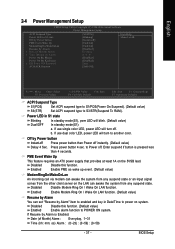
.../POS(Power On Suspend). (Default value) S3(STR) Set ACPI suspend type to power on system. Disabled Disable Modem Ring On / Wake On LAN function. BIOS Setup
.../POS(Power On Suspend). (Default value) S3(STR) Set ACPI suspend type to power on system. Disabled Disable Modem Ring On / Wake On LAN function. BIOS Setup
Manual
Page 39
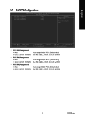
... PCI3 IRQ Assignment Auto 3,4,5,7,9,10,11,12,14,15 Auto assign IRQ to PCI1. (Default value) Set IRQ 3,4,5,7,9,10,11,12,14,15 to PCI2. BIOS Setup Auto assign IRQ to PCI3. (Default value) Set IRQ 3,4,5,7,9,10,11,12,14,15 to PCI3. - 39 -
... PCI3 IRQ Assignment Auto 3,4,5,7,9,10,11,12,14,15 Auto assign IRQ to PCI1. (Default value) Set IRQ 3,4,5,7,9,10,11,12,14,15 to PCI2. BIOS Setup Auto assign IRQ to PCI3. (Default value) Set IRQ 3,4,5,7,9,10,11,12,14,15 to PCI3. - 39 -


