Manual
Page 4
... the CPU 12 1-3-2 Installation of the Heatsink 13 1-4 Installation of Memory 14 1-5 Installation of Expansion Cards 15 1-6 I/O Back Panel Introduction 16 1-7 Connectors Introduction 17 Chapter 2 BIOS Setup 27 The Main Menu (For example: BIOS Ver. : D5 28 2-1 Standard CMOS Features 30 2-2 Advanced BIOS Features 32 2-3 IntegratedPeripherals 34 2-4 Power Management Setup 37 2-5 PnP/PCI Configurations 39 2-6 PC Health Status 40 2-7 Frequency/Voltage Control 42 2-8 Load Fail-Safe Defaults 43 2-9 Load Optimized Defaults 43 2-10 Set Supervisor/User Password 44 2-11 Save & Exit Setup...
... the CPU 12 1-3-2 Installation of the Heatsink 13 1-4 Installation of Memory 14 1-5 Installation of Expansion Cards 15 1-6 I/O Back Panel Introduction 16 1-7 Connectors Introduction 17 Chapter 2 BIOS Setup 27 The Main Menu (For example: BIOS Ver. : D5 28 2-1 Standard CMOS Features 30 2-2 Advanced BIOS Features 32 2-3 IntegratedPeripherals 34 2-4 Power Management Setup 37 2-5 PnP/PCI Configurations 39 2-6 PC Health Status 40 2-7 Frequency/Voltage Control 42 2-8 Load Fail-Safe Defaults 43 2-9 Load Optimized Defaults 43 2-10 Set Supervisor/User Password 44 2-11 Save & Exit Setup...
Manual
Page 10
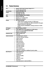
...up to 2GB memory) Š Supports dual channel DDR400/333/266 DIMM Š Supports 2.5V DDR DIMMs Expanstion Slots Š 1 AGP slot 4X/8X (1.5V) Š 3 PCI slots Internal Connectors Š 1 20-pin ATX power connector Š 1 4-pin ATX 12V power connector Š 1 floppy connector Š 2 IDE connectors Š 2 SATA connectors Š 1 CPU fan connector Š 1 system fan connector Š 1 front panel connector Š 1 front audio connector Š 1 CD In connector Š 1 power LED connector Š 1 USB 2.0/1.1 connectors for additional 2 ports by cables Rear Panel...
...up to 2GB memory) Š Supports dual channel DDR400/333/266 DIMM Š Supports 2.5V DDR DIMMs Expanstion Slots Š 1 AGP slot 4X/8X (1.5V) Š 3 PCI slots Internal Connectors Š 1 20-pin ATX power connector Š 1 4-pin ATX 12V power connector Š 1 floppy connector Š 2 IDE connectors Š 2 SATA connectors Š 1 CPU fan connector Š 1 system fan connector Š 1 front panel connector Š 1 front audio connector Š 1 CD In connector Š 1 power LED connector Š 1 USB 2.0/1.1 connectors for additional 2 ports by cables Rear Panel...

Manual
Page 19
... to connect the power to the CPU fan to prevent CPU overheating and failure. 1 CPU_FAN 1 SYS_FAN Pin No. 1 2 3 4 Definition GND +12V Sense Speed Control (Only for information on settings, please refer to the instructions located on one IDE cable, and the single IDE cable can connect to one IDE device as Master and the other as Slave (for CPU_FAN) 5) IDE1/IDE2 (IDE Connector) An IDE device connects to connect two IDE devices, please set the jumper on the IDE device). 40...
... to connect the power to the CPU fan to prevent CPU overheating and failure. 1 CPU_FAN 1 SYS_FAN Pin No. 1 2 3 4 Definition GND +12V Sense Speed Control (Only for information on settings, please refer to the instructions located on one IDE cable, and the single IDE cable can connect to one IDE device as Master and the other as Slave (for CPU_FAN) 5) IDE1/IDE2 (IDE Connector) An IDE device connects to connect two IDE devices, please set the jumper on the IDE device). 40...
Manual
Page 20
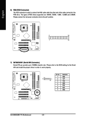
... proper driver in order to 150MB/s transfer rate. Pin No. Definition 1 GND 7 1 2 TXP 3 TXN 4 GND 5 RXN 6 RXP 7 GND GA-8I865GME-775 Motherboard - 20 - Please connect the red power connector wire to the pin1 position. 2 34 1 33 7) SATA0/SATA1 (Serial ATA Connector,) Serial ATA can provide up to work properly. English 6) FDD (FDD Connector) The FDD connector is used to connect the FDD cable while the other end of FDD drives supported...
... proper driver in order to 150MB/s transfer rate. Pin No. Definition 1 GND 7 1 2 TXP 3 TXN 4 GND 5 RXN 6 RXP 7 GND GA-8I865GME-775 Motherboard - 20 - Please connect the red power connector wire to the pin1 position. 2 34 1 33 7) SATA0/SATA1 (Serial ATA Connector,) Serial ATA can provide up to work properly. English 6) FDD (FDD Connector) The FDD connector is used to connect the FDD cable while the other end of FDD drives supported...
Manual
Page 21
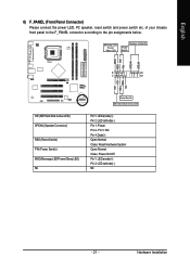
... Installation English 8) F_PANEL (Front Panel Connector) Please connect the power LED, PC speaker, reset switch and power switch etc. RESRES+ NC HD (IDE Hard Disk Active LED) SPEAK (Speaker Connector) RES (Reset Switch) PW (Power Switch) MSG(Message LED/Power/Sleep LED) NC Reset Switch IDE Hard Disk Active LED Pin 1: LED anode(+) Pin 2: LED cathode(-) Pin 1: Power Pin 2- PW+ PWSPEAK+ SPEAK- 2 20 1 19 HD+ HD- Pin 3: NC Pin 4: Data(-) Open: Normal Close: Reset Hardware System Open: Normal Close: Power On/Off Pin 1: LED anode(+) Pin 2: LED cathode(-) NC - 21 - Message LED/ Power...
... Installation English 8) F_PANEL (Front Panel Connector) Please connect the power LED, PC speaker, reset switch and power switch etc. RESRES+ NC HD (IDE Hard Disk Active LED) SPEAK (Speaker Connector) RES (Reset Switch) PW (Power Switch) MSG(Message LED/Power/Sleep LED) NC Reset Switch IDE Hard Disk Active LED Pin 1: LED anode(+) Pin 2: LED cathode(-) Pin 1: Power Pin 2- PW+ PWSPEAK+ SPEAK- 2 20 1 19 HD+ HD- Pin 3: NC Pin 4: Data(-) Open: Normal Close: Reset Hardware System Open: Normal Close: Power On/Off Pin 1: LED anode(+) Pin 2: LED cathode(-) NC - 21 - Message LED/ Power...
Manual
Page 22
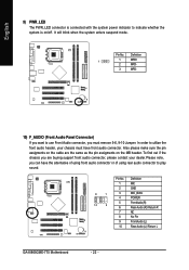
... using front audio connector or of using rear audio connector to play sound. Definition 1 MIC 2 GND 9 1 3 MIC_BIAS 4 POWER 10 2 5 FrontAudio(R) 6 Rear Audio (R)/ Return R 7 NC 8 No Pin 9 FrontAudio (L) 10 Rear Audio (L)/ Return L GA-8I865GME-775 Motherboard - 22 - It will blink when the system enters suspend mode. In order to indicate whether the system is on/off. English 9) PWR_LED The PWR_LED connector is connected with the system power indicator to utilize the front audio header...
... using front audio connector or of using rear audio connector to play sound. Definition 1 MIC 2 GND 9 1 3 MIC_BIAS 4 POWER 10 2 5 FrontAudio(R) 6 Rear Audio (R)/ Return R 7 NC 8 No Pin 9 FrontAudio (L) 10 Rear Audio (L)/ Return L GA-8I865GME-775 Motherboard - 22 - It will blink when the system enters suspend mode. In order to indicate whether the system is on/off. English 9) PWR_LED The PWR_LED connector is connected with the system power indicator to utilize the front audio header...
Manual
Page 28
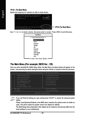
...below) will appear on cards) device. Please Load Optimized Defaults in this menu. GA-8I865GME-775 Motherboard - 28 - CMOS Setup Utility-Copyright (C) 1984-2006 Award Software ` Standard CMOS Features ` Advanced BIOS Features ` Integrated Peripherals ` Power Management Setup ` PnP/PCI Configurations ` PC Health Status ` Frequency/Voltage Control ESC: Quit F8: Q-Flash Load Fail-Safe Defaults Load Optimized Defaults Set Supervisor Password Set User Password Save & Exit Setup Exit Without Saving KLJI: Select Item F10: Save & Exit Setup Time, Date, Hard Disk Type... Press to exit this...
...below) will appear on cards) device. Please Load Optimized Defaults in this menu. GA-8I865GME-775 Motherboard - 28 - CMOS Setup Utility-Copyright (C) 1984-2006 Award Software ` Standard CMOS Features ` Advanced BIOS Features ` Integrated Peripherals ` Power Management Setup ` PnP/PCI Configurations ` PC Health Status ` Frequency/Voltage Control ESC: Quit F8: Q-Flash Load Fail-Safe Defaults Load Optimized Defaults Set Supervisor Password Set User Password Save & Exit Setup Exit Without Saving KLJI: Select Item F10: Save & Exit Setup Time, Date, Hard Disk Type... Press to exit this...
Manual
Page 30
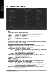
... . IDE Channel 2/3 Master IDE HDD Auto-Detection Press "Enter" to Sat. Jan. IDE Channel 0 Master/Slave ; Access Mode Use this option for the hard drive. The two options are used and the system will skip the automatic detection step and allow for faster system start up . • Manual User can use one of currectly installed hard drive. Week The week, from 1999 through 2098 Time The times format in the month) Base Memory Extended Memory...
... . IDE Channel 2/3 Master IDE HDD Auto-Detection Press "Enter" to Sat. Jan. IDE Channel 0 Master/Slave ; Access Mode Use this option for the hard drive. The two options are used and the system will skip the automatic detection step and allow for faster system start up . • Manual User can use one of currectly installed hard drive. Week The week, from 1999 through 2098 Time The times format in the month) Base Memory Extended Memory...
Manual
Page 32
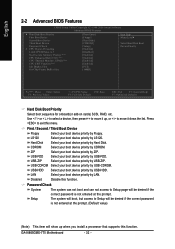
... your boot device priority by USB-CDROM. to exit this menu. Press to 3 No-Execute Memory Protect (Note) CPU Enhanced Halt (C1E) (Note) CPU Thermal Monitor 2(TM2) (Note) CPU EIST Function (Note) Init Display First On-Chip Frame Buffer Size [Press Enter] [Floppy] [Hard Disk] [CDROM] [Setup] [Enabled] [Disabled] [Enabled] [Enabled] [Enabled] [Enabled] [PCI] [16MB] Item Help Menu Level` Select Hard Disk Boot Device Priority KLJI: Move Enter: Select F5: Previous Values +/-/PU/PD: Value F10: Save F6: Fail-Safe Default ESC...
... your boot device priority by USB-CDROM. to exit this menu. Press to 3 No-Execute Memory Protect (Note) CPU Enhanced Halt (C1E) (Note) CPU Thermal Monitor 2(TM2) (Note) CPU EIST Function (Note) Init Display First On-Chip Frame Buffer Size [Press Enter] [Floppy] [Hard Disk] [CDROM] [Setup] [Enabled] [Disabled] [Enabled] [Enabled] [Enabled] [Enabled] [PCI] [16MB] Item Help Menu Level` Select Hard Disk Boot Device Priority KLJI: Move Enter: Select F5: Previous Values +/-/PU/PD: Value F10: Save F6: Fail-Safe Default ESC...
Manual
Page 34
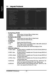
...compatible mode. GA-8I865GME-775 Motherboard - 34 - Master Set SATA controller to native mode(Serial ATA mode - IDE Pri. On-Chip SATA Disabled Disable onboard Seria ATA function. English 2-3 Integrated Peripherals CMOS Setup Utility-Copyright (C) 1984-2006 Award Software Integrated Peripherals On-Chip Primary PCI IDE On-Chip Secondary PCI IDE On-Chip SATA x SATA Port0 configure as SATA Port1 configure as USB Controller USB 2.0 Controller USB Keyboard Support USB Mouse Support Legacy USB storage detect AC97 Audio Onboard H/W LAN OnBoard LAN Boot ROM Onboard Serial Port 1 Onboard...
...compatible mode. GA-8I865GME-775 Motherboard - 34 - Master Set SATA controller to native mode(Serial ATA mode - IDE Pri. On-Chip SATA Disabled Disable onboard Seria ATA function. English 2-3 Integrated Peripherals CMOS Setup Utility-Copyright (C) 1984-2006 Award Software Integrated Peripherals On-Chip Primary PCI IDE On-Chip Secondary PCI IDE On-Chip SATA x SATA Port0 configure as SATA Port1 configure as USB Controller USB 2.0 Controller USB Keyboard Support USB Mouse Support Legacy USB storage detect AC97 Audio Onboard H/W LAN OnBoard LAN Boot ROM Onboard Serial Port 1 Onboard...
Manual
Page 44
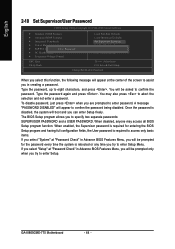
... of the screen to assist you in Advance BIOS Features Menu, you will be prompted for the password every time the system is disabled, the system will boot and you can enter Setup freely. English 2-10 Set Supervisor/User Password CMOS Setup Utility-Copyright (C) 1984-2006 Award Software ` Standard CMOS Features ` Advanced BIOS Features ` Integrated Peripherals ` Power Management Setup ` PnP/PCI ConfiguratioEnsnter Password: ` PC Health Status ` Frequency/Voltage Control Load Fail-Safe Defaults Load Optimized Defaults Set Supervisor Password Set User Password Save & Exit Setup Exit...
... of the screen to assist you in Advance BIOS Features Menu, you will be prompted for the password every time the system is disabled, the system will boot and you can enter Setup freely. English 2-10 Set Supervisor/User Password CMOS Setup Utility-Copyright (C) 1984-2006 Award Software ` Standard CMOS Features ` Advanced BIOS Features ` Integrated Peripherals ` Power Management Setup ` PnP/PCI ConfiguratioEnsnter Password: ` PC Health Status ` Frequency/Voltage Control Load Fail-Safe Defaults Load Optimized Defaults Set Supervisor Password Set User Password Save & Exit Setup Exit...
Manual
Page 51
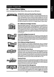
.... Download Center Download Center allows users to quickly download and update their system. M.I.T. (Motherboard Intelligent Tweaker) Motherboard Intelligent Tweaker (M.I .B. 2) is designed especially to maximize memory performance and boost memory bandwidth up the PC chassis and short-circuit the "Clear CMOS" pins or the battery on the U-Plus D.P.S. Through GIGABYTE M.I .T.'s integration of all platform performance settings into different modes within BIOS setup in order to change BIOS feature settings with the option for download. feature the user...
.... Download Center Download Center allows users to quickly download and update their system. M.I.T. (Motherboard Intelligent Tweaker) Motherboard Intelligent Tweaker (M.I .B. 2) is designed especially to maximize memory performance and boost memory bandwidth up the PC chassis and short-circuit the "Clear CMOS" pins or the battery on the U-Plus D.P.S. Through GIGABYTE M.I .T.'s integration of all platform performance settings into different modes within BIOS setup in order to change BIOS feature settings with the option for download. feature the user...
Manual
Page 52
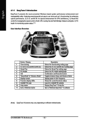
... .B. Function display LEDs 9. GA-8I865GME-775 Motherboard - 52 - Overclocking 2. "Easy Mode" & "Advance Mode" 7. Featuring several powerful yet easy to GIGABYTE website Display EasyTuneTM 5 Help file Quit or Minimize EasyTuneTM 5 software (Note) EasyTune 5 functions may vary depending on to use tools such as 1) Overclocking for monitoring system status.(Note) User Interface Overview Button / Display 1. GIGABYTE Logo 10. Help button 11. PC Health 5. for special enhancement for CPU and Memory, 3) Smart-Fan control for managing fan speed control of CPU frequency Shows the...
... .B. Function display LEDs 9. GA-8I865GME-775 Motherboard - 52 - Overclocking 2. "Easy Mode" & "Advance Mode" 7. Featuring several powerful yet easy to GIGABYTE website Display EasyTuneTM 5 Help file Quit or Minimize EasyTuneTM 5 software (Note) EasyTune 5 functions may vary depending on to use tools such as 1) Overclocking for monitoring system status.(Note) User Interface Overview Button / Display 1. GIGABYTE Logo 10. Help button 11. PC Health 5. for special enhancement for CPU and Memory, 3) Smart-Fan control for managing fan speed control of CPU frequency Shows the...
Manual
Page 53
... installations of system memory 3. System storage capacity and the reading/writing speed of hard disk data. Appendix System requirements: 1. Save the settings and exit the BIOS Setup. It is executed from the CD-ROM, you can simply press F9 during system power-on PATA and SATA IDE controllers. Intel x86 platforms 2. At least 64M bytes of OS and all required drivers as well as software. - 53 - GA-8I865GME-775...
... installations of system memory 3. System storage capacity and the reading/writing speed of hard disk data. Appendix System requirements: 1. Save the settings and exit the BIOS Setup. It is executed from the CD-ROM, you can simply press F9 during system power-on PATA and SATA IDE controllers. Intel x86 platforms 2. At least 64M bytes of OS and all required drivers as well as software. - 53 - GA-8I865GME-775...

Manual
Page 56
... Language Load Fail-Safe Defaults Load Optimized Defaults Set Supervisor Password Set User Password Save & Exit Setup Exit Without Saving F3: Change Language F10: Save & Exit Setup Time, Date, Hard Disk Type... Task menu for Dual BIOS utility Task menu for Dual BIOS utility: Contains the names of the following key components. Blocking a task and pressing Enter key on your keyboard to Floppy Enter : Run :Move ESC:Reset F10:Power Off Dual BIOS utility bar Q-FlashTM utility title bar Action bar Task menu for Q-FlashTM utility Dual BIOS Utility Boot From Main Bios Main ROM Type/Size...
... Language Load Fail-Safe Defaults Load Optimized Defaults Set Supervisor Password Set User Password Save & Exit Setup Exit Without Saving F3: Change Language F10: Save & Exit Setup Time, Date, Hard Disk Type... Task menu for Dual BIOS utility Task menu for Dual BIOS utility: Contains the names of the following key components. Blocking a task and pressing Enter key on your keyboard to Floppy Enter : Run :Move ESC:Reset F10:Power Off Dual BIOS utility bar Q-FlashTM utility title bar Action bar Task menu for Q-FlashTM utility Dual BIOS Utility Boot From Main Bios Main ROM Type/Size...
Manual
Page 58
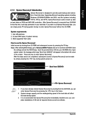
... Type/Size SST 49LF003A 512K 512K Wide Range Protection Disable Boot From Main Bios AutoARreecyoovuersyure EtonaRbEleSET ? The computer will be displayed. English 3. Press any keys to return to enter SETUP / Dual BIOS / Q-Flash / F9 For Xpress Recovery 09/23/2003-i875P-6A79BG03C-00 GA-8I865GME-775 Motherboard - 58 - Pass !! Halt On Error Disable CPopleyasMe apirneRssOaMnyDkaetya tto cBoanctkiunpue Load Default Settings Save Settings to CMOS Q-Flash Utility Load Main BIOS from Floppy Load Backup BIOS from Floppy Save Main BIOS to Floppy Save Backup BIOS to update BIOS...
... Type/Size SST 49LF003A 512K 512K Wide Range Protection Disable Boot From Main Bios AutoARreecyoovuersyure EtonaRbEleSET ? The computer will be displayed. English 3. Press any keys to return to enter SETUP / Dual BIOS / Q-Flash / F9 For Xpress Recovery 09/23/2003-i875P-6A79BG03C-00 GA-8I865GME-775 Motherboard - 58 - Pass !! Halt On Error Disable CPopleyasMe apirneRssOaMnyDkaetya tto cBoanctkiunpue Load Default Settings Save Settings to CMOS Q-Flash Utility Load Main BIOS from Floppy Load Backup BIOS from Floppy Save Main BIOS to Floppy Save Backup BIOS to update BIOS...
Manual
Page 59
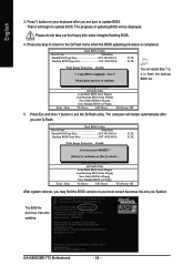
...: Dual BIOS/Q-Flash F3: Change Language F10: Save & Exit Setup Time, Date, Hard Disk Type... System will reboot after BIOS has been upgraded. The procedure is completed. Part Two: Updating BIOS with Q-FlashTM Utility on your keyboard to save and exit. Normally the system redetects all devices after you are in BIOS menu, move to Load Fail-Safe Defaults item and press Enter to update BIOS using the Q-FlashTM utility. Press Y on Single-BIOS Motherboards. Appendix This part guides users of...
...: Dual BIOS/Q-Flash F3: Change Language F10: Save & Exit Setup Time, Date, Hard Disk Type... System will reboot after BIOS has been upgraded. The procedure is completed. Part Two: Updating BIOS with Q-FlashTM Utility on your keyboard to save and exit. Normally the system redetects all devices after you are in BIOS menu, move to Load Fail-Safe Defaults item and press Enter to update BIOS using the Q-FlashTM utility. Press Y on Single-BIOS Motherboards. Appendix This part guides users of...
Manual
Page 62
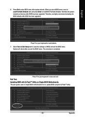
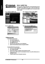
... use the new @BIOS utility. @BIOS allows users to download the latest version of BIOS. Installing the @BIOS utility Fig 2. Click "Update New BIOS" icon c. System will automatically download and update the BIOS. d. Installation Complete and Run @BIOS Select @BIOS item Fig 3. Select the desired @BIOS server 1. Click "Internet Update" icon b. Do not click "Internet Update" icon b. Click "Update New BIOS" c. e. Please select "All Files" in dialog box while opening the old file. GA-8I865GME-775 Motherboard - 62 - Update BIOS through Internet: a. Update BIOS...
... use the new @BIOS utility. @BIOS allows users to download the latest version of BIOS. Installing the @BIOS utility Fig 2. Click "Update New BIOS" icon c. System will automatically download and update the BIOS. d. Installation Complete and Run @BIOS Select @BIOS item Fig 3. Select the desired @BIOS server 1. Click "Internet Update" icon b. Do not click "Internet Update" icon b. Click "Update New BIOS" c. e. Please select "All Files" in dialog box while opening the old file. GA-8I865GME-775 Motherboard - 62 - Update BIOS through Internet: a. Update BIOS...
Manual
Page 64
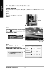
... taskbar. STEP 1: Connect the stereo speakers or earphone to select the function. Click the icon to "Line Out." GA-8I865GME-775 Motherboard - 64 - Line Out STEP 2: After installing the audio driver, you use speakers with amplifier to get the best sound effect if the stereo output is applied. STEP 3: On the AC97 Audio Configuration menu, click the Speaker Configuration tab and select the 2-channel mode for stereo speaker output check...
... taskbar. STEP 1: Connect the stereo speakers or earphone to select the function. Click the icon to "Line Out." GA-8I865GME-775 Motherboard - 64 - Line Out STEP 2: After installing the audio driver, you use speakers with amplifier to get the best sound effect if the stereo output is applied. STEP 3: On the AC97 Audio Configuration menu, click the Speaker Configuration tab and select the 2-channel mode for stereo speaker output check...
Manual
Page 67
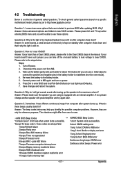
... were included in the manual. Question 4: Why do these options. gate A20 failure 7 beeps Processor exception interrupt error 8 beeps Display memory read/write failure 9 beeps ROM checksum error 10 beeps CMOS shutdown register read/write error 11 beeps Cache memory bad AWARD BIOS Beep Codes 1 short: System boots successfully 2 short: CMOS setting error 1 long 1 short: DRAM or M/B error 1 long 2 short: Monitor or display card error 1 long 3 short: Keyboard error 1 long 9 short: BIOS ROM error Continuous long beeps: DRAM error Continuous short beeps: Power error - 67 - To check...
... were included in the manual. Question 4: Why do these options. gate A20 failure 7 beeps Processor exception interrupt error 8 beeps Display memory read/write failure 9 beeps ROM checksum error 10 beeps CMOS shutdown register read/write error 11 beeps Cache memory bad AWARD BIOS Beep Codes 1 short: System boots successfully 2 short: CMOS setting error 1 long 1 short: DRAM or M/B error 1 long 2 short: Monitor or display card error 1 long 3 short: Keyboard error 1 long 9 short: BIOS ROM error Continuous long beeps: DRAM error Continuous short beeps: Power error - 67 - To check...


