
Manual
Page 5
Table of Contents ItemChecklist ...7 OptionalAccessories ...7 GA-8I865G775-G(-RH) Motherboard Layout 8 Block Diagram ...9 Chapter 1 Hardware Installation 11 1-1 Considerations Prior to Installation 11 1-2 Feature Summary 12 1-3 Installation...16 1-5 Installation of Expansion Cards 17 1-6 I/O Back Panel Introduction 18 1-7 Connectors Introduction 19 Chapter 2 BIOS Setup 31 The Main Menu (For example: BIOS Ver. : D11 32 2-1 Standard CMOS Features 34 2-2 Advanced BIOS Features 36 2-3 IntegratedPeripherals 38 2-4 Power Management Setup 41 2-5 PnP/PCI Configurations 43 2-6 PC Health ...
Table of Contents ItemChecklist ...7 OptionalAccessories ...7 GA-8I865G775-G(-RH) Motherboard Layout 8 Block Diagram ...9 Chapter 1 Hardware Installation 11 1-1 Considerations Prior to Installation 11 1-2 Feature Summary 12 1-3 Installation...16 1-5 Installation of Expansion Cards 17 1-6 I/O Back Panel Introduction 18 1-7 Connectors Introduction 19 Chapter 2 BIOS Setup 31 The Main Menu (For example: BIOS Ver. : D11 32 2-1 Standard CMOS Features 34 2-2 Advanced BIOS Features 36 2-3 IntegratedPeripherals 38 2-4 Power Management Setup 41 2-5 PnP/PCI Configurations 43 2-6 PC Health ...

Manual
Page 6
Chapter 3 Drivers Installation 53 3-1 Install Chipset Drivers 53 3-2 SoftwareApplications 54 3-3 Driver CD Information 54 3-4 Hardware Information 55 3-5 Contact Us ...55 Chapter 4 Appendix 57 4-1 Unique Software Utilities 57 4-1-1 EasyTune 5 Introduction 57 4-1-2 Xpress Recovery2 Introduction 58 4-1-3 Flash BIOS Method Introduction 60 4-1-4 2 / 4 / 6 Channel Audio Function Introduction 69 4-2 Troubleshooting 75 - 6 -
Chapter 3 Drivers Installation 53 3-1 Install Chipset Drivers 53 3-2 SoftwareApplications 54 3-3 Driver CD Information 54 3-4 Hardware Information 55 3-5 Contact Us ...55 Chapter 4 Appendix 57 4-1 Unique Software Utilities 57 4-1-1 EasyTune 5 Introduction 57 4-1-2 Xpress Recovery2 Introduction 58 4-1-3 Flash BIOS Method Introduction 60 4-1-4 2 / 4 / 6 Channel Audio Function Introduction 69 4-2 Troubleshooting 75 - 6 -

Manual
Page 8
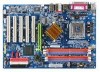
GA-8I865G775-G(-RH) Motherboard Layout KB_MS LGA775 ATX_12V CPU_FAN COMA LPT GA-8I865G775 -G(-RH) DDR1 VGA ATX R_USB USB_LAN AUDIO F_AUDIO Intel 865G DDR4 DDR3 DDR2 AGP Marvell 8001 CODEC CD_IN SUR_CEN IT8712 AUX_IN CI COMB SPDIF_O PCI1 ICH5 PCI2 IDE1 IDE2 BAT CLR_CMOS FDD PCI3 SATA0 PCI4 BIOS SATA1 PCI5 SYS _FAN F_USB1 F_USB2 F_PANEL PWR_LED - 8 -
GA-8I865G775-G(-RH) Motherboard Layout KB_MS LGA775 ATX_12V CPU_FAN COMA LPT GA-8I865G775 -G(-RH) DDR1 VGA ATX R_USB USB_LAN AUDIO F_AUDIO Intel 865G DDR4 DDR3 DDR2 AGP Marvell 8001 CODEC CD_IN SUR_CEN IT8712 AUX_IN CI COMB SPDIF_O PCI1 ICH5 PCI2 IDE1 IDE2 BAT CLR_CMOS FDD PCI3 SATA0 PCI4 BIOS SATA1 PCI5 SYS _FAN F_USB1 F_USB2 F_PANEL PWR_LED - 8 -

Manual
Page 9
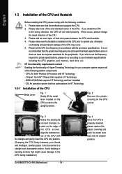
Block Diagram AGP 8X/4X VGA LGA775 Processor Host Interface Intel 865G GMCH DDR 400/333/266MHz DIMM Dual Channel Memory PCI Bus Intel ICH5 Marvell 8001 RJ45 5 PCI PCICLK (33MHz) MIC Line-Out Line-In CODEC 8 USB Ports BIOS 2 Serial ATA ATA33/66/100 IDE Channels IT8712 Floppy LPT Port COM Ports PS/2 KB/Mouse - 9 -
Block Diagram AGP 8X/4X VGA LGA775 Processor Host Interface Intel 865G GMCH DDR 400/333/266MHz DIMM Dual Channel Memory PCI Bus Intel ICH5 Marvell 8001 RJ45 5 PCI PCICLK (33MHz) MIC Line-Out Line-In CODEC 8 USB Ports BIOS 2 Serial ATA ATA33/66/100 IDE Channels IT8712 Floppy LPT Port COM Ports PS/2 KB/Mouse - 9 -

Manual
Page 13
...Š CPU warning temperature Š CPU System fan failure warning Š CPU smart fan control BIOS Š 1 4Mbit flash ROM Š Use of licensed AWARD BIOS Additional Features Š Supports @BIOS Š Supports Download Center Š Supports Q-Flash Š Supports EasyTune (only supports Hardware Monitor... (OEM version) Form Factor Š ATX form factor; 30.5cm x 21cm (Note 1) For further CPU support information, please go to GIGABYTE's website. (Note 2) Due to standard PC architecture, a certain amount of memory size will instead be shown as 3.xxGB memory during system ...
...Š CPU warning temperature Š CPU System fan failure warning Š CPU smart fan control BIOS Š 1 4Mbit flash ROM Š Use of licensed AWARD BIOS Additional Features Š Supports @BIOS Š Supports Download Center Š Supports Q-Flash Š Supports EasyTune (only supports Hardware Monitor... (OEM version) Form Factor Š ATX form factor; 30.5cm x 21cm (Note 1) For further CPU support information, please go to GIGABYTE's website. (Note 2) Due to standard PC architecture, a certain amount of memory size will instead be shown as 3.xxGB memory during system ...
Manual
Page 14
... peripherals. Please take note of the one indented corner of the CPU socket. Please add an even layer of the CPU may occur. 5. BIOS: A BIOS that the motherboard supports the CPU. 2. Align the indented corner of the CPU with the triangle and gently insert the CPU into position. ... Before installing the CPU, please comply with HT Technology - Fig. 2 Remove the plastic covering on the CPU socket to the CPU during installation.) GA-8I865G775-G(-RH) Motherboard - 14 - If you install the CPU in the wrong direction, the CPU will not insert properly. It is properly inserted, please...
... peripherals. Please take note of the one indented corner of the CPU socket. Please add an even layer of the CPU may occur. 5. BIOS: A BIOS that the motherboard supports the CPU. 2. Align the indented corner of the CPU with the triangle and gently insert the CPU into position. ... Before installing the CPU, please comply with HT Technology - Fig. 2 Remove the plastic covering on the CPU socket to the CPU during installation.) GA-8I865G775-G(-RH) Motherboard - 14 - If you install the CPU in the wrong direction, the CPU will not insert properly. It is properly inserted, please...

Manual
Page 16
... recommended that they can only fit in one direction. Memory modules have a foolproof insertion design. DDR memory module Fig. 1 Fig. 2 GA-8I865G775-G(-RH) Motherboard - 16 - The motherboard supports DDR memory modules, whereby BIOS will automatically detect memory capacity and specifications. The memory capacity used . 2. notch Fig.1 The DIMM socket has a notch, so the...
... recommended that they can only fit in one direction. Memory modules have a foolproof insertion design. DDR memory module Fig. 1 Fig. 2 GA-8I865G775-G(-RH) Motherboard - 16 - The motherboard supports DDR memory modules, whereby BIOS will automatically detect memory capacity and specifications. The memory capacity used . 2. notch Fig.1 The DIMM socket has a notch, so the...

Manual
Page 17
Read the related expansion card's instruction document before installing the expansion card into expansion slot in the slot. 5. Install related driver from BIOS. 8. Press the expansion card firmly into the computer. 2. Be sure the metal contacts on the card are indeed seated in motherboard. 4. Replace ...slot bracket of the AGP slot when you try to the onboard AGP slot and press firmly down on the computer, if necessary, setup BIOS utility of expansion card from the operating system. Please align the VGA card to install/uninstall the VGA card. Remove your expansion card by...
Read the related expansion card's instruction document before installing the expansion card into expansion slot in the slot. 5. Install related driver from BIOS. 8. Press the expansion card firmly into the computer. 2. Be sure the metal contacts on the card are indeed seated in motherboard. 4. Replace ...slot bracket of the AGP slot when you try to the onboard AGP slot and press firmly down on the computer, if necessary, setup BIOS utility of expansion card from the operating system. Please align the VGA card to install/uninstall the VGA card. Remove your expansion card by...

Manual
Page 22
Pin No. Definition 1 GND 7 1 2 TXP 3 TXN 4 GND 5 RXN 6 RXP 7 GND GA-8I865G775-G(-RH) Motherboard - 22 - The types of the foolproof groove in order to the FDD drive. Before attaching the FDD cable, please take note of FDD ...) The FDD connector is used to connect the FDD cable while the other end of the cable connects to work properly. Please refer to the BIOS setting for the Serial ATA and install the proper driver in the FDD connector. 34 33 2 1 7) SATA0/SATA1 (Serial ATA Connector,) Serial ATA can provide...
Pin No. Definition 1 GND 7 1 2 TXP 3 TXN 4 GND 5 RXN 6 RXP 7 GND GA-8I865G775-G(-RH) Motherboard - 22 - The types of the foolproof groove in order to the FDD drive. Before attaching the FDD cable, please take note of FDD ...) The FDD connector is used to connect the FDD cable while the other end of the cable connects to work properly. Please refer to the BIOS setting for the Serial ATA and install the proper driver in the FDD connector. 34 33 2 1 7) SATA0/SATA1 (Serial ATA Connector,) Serial ATA can provide...

Manual
Page 28
English 17) CI (Chassis Intrusion, Case Open) This 2-pin connector allows your system to avoid improper use of this header. You can check the "Case Opened" status in BIOS Setup. Definition 1 1 Signal 2 GND 18) CLR_CMOS (Clear CMOS) You may clear the CMOS data to its default values by this header. Default doesn't include the jumper to detect if the chassis cover is removed. To clear CMOS, temporarily short the two pins. Pin No. Open: Normal Short: Clear CMOS GA-8I865G775-G(-RH) Motherboard - 28 -
English 17) CI (Chassis Intrusion, Case Open) This 2-pin connector allows your system to avoid improper use of this header. You can check the "Case Opened" status in BIOS Setup. Definition 1 1 Signal 2 GND 18) CLR_CMOS (Clear CMOS) You may clear the CMOS data to its default values by this header. Default doesn't include the jumper to detect if the chassis cover is removed. To clear CMOS, temporarily short the two pins. Pin No. Open: Normal Short: Clear CMOS GA-8I865G775-G(-RH) Motherboard - 28 -

Manual
Page 31
... to a new BIOS, either GIGABYTE's Q-Flash or @BIOS utility can enter the BIOS setup screen by pressing "Ctrl + F1". Exit current page and return to use and the possible selections for Option Page Setup Menu Load the file-safe default CMOS value from the Internet. BIOS Setup CONTROL KEYS Enter...first time, it with caution and avoid inadequate operation that does not require users to boot to the CMOS SRAM. English Chapter 2 BIOS Setup BIOS (Basic Input and Output System) includes a CMOS SETUP utility which allows user to configure required settings or to select item Select Item ...
... to a new BIOS, either GIGABYTE's Q-Flash or @BIOS utility can enter the BIOS setup screen by pressing "Ctrl + F1". Exit current page and return to use and the possible selections for Option Page Setup Menu Load the file-safe default CMOS value from the Internet. BIOS Setup CONTROL KEYS Enter...first time, it with caution and avoid inadequate operation that does not require users to boot to the CMOS SRAM. English Chapter 2 BIOS Setup BIOS (Basic Input and Output System) includes a CMOS SETUP utility which allows user to configure required settings or to select item Select Item ...

Manual
Page 32
... and may differ from the exact settings for your motherboard. English : For Boot Menu Select boot sequence for onboard (or add-on the screen. GA-8I865G775-G D7 . . . . :BIOS Setup/Q-Flash, : Xpress Recovery2, For Boot Menu 02/22/2006-i865G-6A79AG0VC-00 For Boot Menu Use < > or < > to select ... to select among the items and press to accept . The BIOS Setup menus described in the BIOS when somehow the system works not stable as figure below) will appear on cards) device. GA-8I865G775-G(-RH) Motherboard - 32 - Award Modular BIOS v6.00PG, An Energy Star Ally Copyright (C) 1984-2006, ...
... and may differ from the exact settings for your motherboard. English : For Boot Menu Select boot sequence for onboard (or add-on the screen. GA-8I865G775-G D7 . . . . :BIOS Setup/Q-Flash, : Xpress Recovery2, For Boot Menu 02/22/2006-i865G-6A79AG0VC-00 For Boot Menu Use < > or < > to select ... to select among the items and press to accept . The BIOS Setup menus described in the BIOS when somehow the system works not stable as figure below) will appear on cards) device. GA-8I865G775-G(-RH) Motherboard - 32 - Award Modular BIOS v6.00PG, An Energy Star Ally Copyright (C) 1984-2006, ...

Manual
Page 33
...CMOS Features This setup page includes all the items in best performance configuration. „ Set Supervisor Password Change, set , or disable password. BIOS Setup It allows you to limit access to the system. „ Save & Exit Setup Save CMOS value settings to Setup. „ Set...„ Load Optimized Defaults Optimized Defaults indicates the value of the system parameters which the system would be in standard compatible BIOS. „ Advanced BIOS Features This setup page includes all the items of Award special enhanced features. „ Integrated Peripherals This setup page includes ...
...CMOS Features This setup page includes all the items in best performance configuration. „ Set Supervisor Password Change, set , or disable password. BIOS Setup It allows you to limit access to the system. „ Save & Exit Setup Save CMOS value settings to Setup. „ Set...„ Load Optimized Defaults Optimized Defaults indicates the value of the system parameters which the system would be in standard compatible BIOS. „ Advanced BIOS Features This setup page includes all the items of Award special enhanced features. „ Integrated Peripherals This setup page includes ...

Manual
Page 34
...; Manual User can use one of three methods: • Auto Allows BIOS to automatically detect IDE devices during POST(default) • None Select this if no IDE devices are : Large/Auto(default:Auto) GA-8I865G775-G(-RH) Motherboard - 34 - The time is 13:00:00. Access Mode... maximum allowed in . The four options are: CHS/LBA/Large/Auto(default:Auto) Capacity Capacity of the two methods: • Auto Allows BIOS to automatically detect IDE devices during POST. (Default value) • None Select this option for faster system start up . English 2-1 Standard CMOS...
...; Manual User can use one of three methods: • Auto Allows BIOS to automatically detect IDE devices during POST(default) • None Select this if no IDE devices are : Large/Auto(default:Auto) GA-8I865G775-G(-RH) Motherboard - 34 - The time is 13:00:00. Access Mode... maximum allowed in . The four options are: CHS/LBA/Large/Auto(default:Auto) Capacity Capacity of the two methods: • Auto Allows BIOS to automatically detect IDE devices during POST. (Default value) • None Select this option for faster system start up . English 2-1 Standard CMOS...

Manual
Page 35
... double-sided drive; 720K byte capacity 1.44M, 3.5" 3.5 inch double-sided drive; 1.44M byte capacity. 2.88M, 3.5" 3.5 inch double-sided drive; 2.88M byte capacity. BIOS Setup None 360K, 5.25" No floppy drive installed 5.25 inch PC-type standard drive; 360K byte capacity. 1.2M, 5.25" 5.25 inch AT-type high-density... hard drive. it will not stop for a disk error; it will not stop for a keyboard or disk error; Extended Memory The BIOS determines how much extended memory is 3 mode Floppy Drive. All, But Disk/Key The system boot will stop for all other errors. ...
... double-sided drive; 720K byte capacity 1.44M, 3.5" 3.5 inch double-sided drive; 1.44M byte capacity. 2.88M, 3.5" 3.5 inch double-sided drive; 2.88M byte capacity. BIOS Setup None 360K, 5.25" No floppy drive installed 5.25 inch PC-type standard drive; 360K byte capacity. 1.2M, 5.25" 5.25 inch AT-type high-density... hard drive. it will not stop for a disk error; it will not stop for a keyboard or disk error; Extended Memory The BIOS determines how much extended memory is 3 mode Floppy Drive. All, But Disk/Key The system boot will stop for all other errors. ...

Manual
Page 36
...will be denied if the correct password is not entered at the prompt. English 2-2 Advanced BIOS Features CMOS Setup Utility-Copyright (C) 1984-2006 Award Software Advanced BIOS Features ` Hard Disk Boot Priority First Boot Device Second Boot Device Third Boot Device Password ...Check # CPU Hyper-Threading Limit CPUID Max. Hard Disk Boot Priority Select boot sequence for onboard(or add-on cards) SCSI, RAID, etc. Hard Disk Select your boot device priority by Hard Disk. GA-8I865G775...
...will be denied if the correct password is not entered at the prompt. English 2-2 Advanced BIOS Features CMOS Setup Utility-Copyright (C) 1984-2006 Award Software Advanced BIOS Features ` Hard Disk Boot Priority First Boot Device Second Boot Device Third Boot Device Password ...Check # CPU Hyper-Threading Limit CPUID Max. Hard Disk Boot Priority Select boot sequence for onboard(or add-on cards) SCSI, RAID, etc. Hard Disk Select your boot device priority by Hard Disk. GA-8I865G775...
Manual
Page 37
... Maximum value to 8MB. CPU Thermal Monitor 2 (TM2) (Note) Enabled Enable CPU Thermal Monitor 2 (TM2) function. (Default value) Disabled Disable CPU Thermal Monitor 2 (TM2) function. BIOS Setup Please note that this function. - 37 - Limit CPUID Max. CPU EIST Function (Note) Enabled Disabled Enable CPU EIST function. (Default value) Disable EIST function...
... Maximum value to 8MB. CPU Thermal Monitor 2 (TM2) (Note) Enabled Enable CPU Thermal Monitor 2 (TM2) function. (Default value) Disabled Disable CPU Thermal Monitor 2 (TM2) function. BIOS Setup Please note that this function. - 37 - Limit CPUID Max. CPU EIST Function (Note) Enabled Disabled Enable CPU EIST function. (Default value) Disable EIST function...

Manual
Page 39
...IRQ4 2E8/IRQ3 Enable onboard Serial port 2 and address is 2F8. (Default value) Enable onboard Serial port 2 and address is 3E8. BIOS Setup Disable this function. USB Keyboard Support Enabled Disabled Enable USB keyboard support. Enabled Disabled Enable USB 2.0 controller. (Default value) Disable USB...Disabled Enable this function if you are not using onboard USB 2.0 feature. Disabled Disable onboard Serial port 1. Onboard Serial Port 2 Auto BIOS will automatically setup the Serial port 1 address. 3F8/IRQ4 2F8/IRQ3 Enable onboard Serial port 1 and address is 3F8. (Default ...
...IRQ4 2E8/IRQ3 Enable onboard Serial port 2 and address is 2F8. (Default value) Enable onboard Serial port 2 and address is 3E8. BIOS Setup Disable this function. USB Keyboard Support Enabled Disabled Enable USB keyboard support. Enabled Disabled Enable USB 2.0 controller. (Default value) Disable USB...Disabled Enable this function if you are not using onboard USB 2.0 feature. Disabled Disable onboard Serial port 1. Onboard Serial Port 2 Auto BIOS will automatically setup the Serial port 1 address. 3F8/IRQ4 2F8/IRQ3 Enable onboard Serial port 1 and address is 3F8. (Default ...

Manual
Page 41
... type to Power off. Enabled Enable Modem Ring On / Wake On LAN function. (Default value) - 41 - Disabled Disable Modem Ring On / Wake On LAN function. BIOS Setup
... type to Power off. Enabled Enable Modem Ring On / Wake On LAN function. (Default value) - 41 - Disabled Disable Modem Ring On / Wake On LAN function. BIOS Setup

Manual
Page 43
... IRQ Assignment Auto Auto assign IRQ to PCI2. (Default value) 3,4,5,7,9,10,11,12,14,15 Set IRQ 3,4,5,7,9,10,11,12,14,15 to PCI1/PCI5. BIOS Setup English 2-5 PnP/PCI Configurations CMOS Setup Utility-Copyright (C) 1984-2006 Award Software PnP/PCI Configurations PCI1/PCI5 IRQ Assignment PCI2 IRQ Assignment PCI3 IRQ...
... IRQ Assignment Auto Auto assign IRQ to PCI2. (Default value) 3,4,5,7,9,10,11,12,14,15 Set IRQ 3,4,5,7,9,10,11,12,14,15 to PCI1/PCI5. BIOS Setup English 2-5 PnP/PCI Configurations CMOS Setup Utility-Copyright (C) 1984-2006 Award Software PnP/PCI Configurations PCI1/PCI5 IRQ Assignment PCI2 IRQ Assignment PCI3 IRQ...


