Manual
Page 3
...order to use of this manual is protected by copyright laws and is 1.0. For instructions on your motherboard revision before updating motherboard BIOS, drivers, or when looking for technical information. Example: All rights reserved. Disclaimer Information in any means without prior notice. ...For example, "REV: 1.0" means the revision of this manual may be made by any form or by GIGABYTE without GIGABYTE's prior written permission. Check your motherboard looks like this manual are legally registered to the specifications and features in this : ...
...order to use of this manual is protected by copyright laws and is 1.0. For instructions on your motherboard revision before updating motherboard BIOS, drivers, or when looking for technical information. Example: All rights reserved. Disclaimer Information in any means without prior notice. ...For example, "REV: 1.0" means the revision of this manual may be made by any form or by GIGABYTE without GIGABYTE's prior written permission. Check your motherboard looks like this manual are legally registered to the specifications and features in this : ...
Manual
Page 4
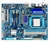
Table of Contents Box Contents...6 Optional Items...6 GA-890XA-UD3 Motherboard Layout 7 GA-890XA-UD3 Motherboard Block Diagram 8 Chapter 1 Hardware Installation 9 1-1 Installation Precautions 9 1-2 Product Specifications 10 1-3 Installing the CPU and CPU ...™ Configuration 19 1-7 Back Panel Connectors 20 1-8 Internal Connectors 22 Chapter 2 BIOS Setup 33 2-1 Startup Screen 34 2-2 The Main Menu 35 2-3 MB Intelligent Tweaker(M.I.T 37 2-4 Standard CMOS Features 43 2-5 Advanced BIOS Features 45 2-6 Integrated Peripherals 47 2-7 Power Management Setup 50 2-8 PC Health Status...
Table of Contents Box Contents...6 Optional Items...6 GA-890XA-UD3 Motherboard Layout 7 GA-890XA-UD3 Motherboard Block Diagram 8 Chapter 1 Hardware Installation 9 1-1 Installation Precautions 9 1-2 Product Specifications 10 1-3 Installing the CPU and CPU ...™ Configuration 19 1-7 Back Panel Connectors 20 1-8 Internal Connectors 22 Chapter 2 BIOS Setup 33 2-1 Startup Screen 34 2-2 The Main Menu 35 2-3 MB Intelligent Tweaker(M.I.T 37 2-4 Standard CMOS Features 43 2-5 Advanced BIOS Features 45 2-6 Integrated Peripherals 47 2-7 Power Management Setup 50 2-8 PC Health Status...
Manual
Page 5
...60 3-7 New Utilities...60 Chapter 4 Unique Features 61 4-1 Xpress Recovery2 61 4-2 BIOS Update Utilities 64 4-2-1 Updating the BIOS with the Q-Flash Utility 64 4-2-2 Updating the BIOS with the @BIOS Utility 67 4-3 EasyTune 6...68 4-4 Easy Energy Saver 69 4-5 Q-Share...71 ...4-6 SMART Recovery 72 Chapter 5 Appendix...73 5-1 Configuring SATA Hard Drive(s 73 5-1-1 Configuring AMD SB850 SATA Controller 73 5-1-2 Configuring JMicron JMB362/GIGABYTE...
...60 3-7 New Utilities...60 Chapter 4 Unique Features 61 4-1 Xpress Recovery2 61 4-2 BIOS Update Utilities 64 4-2-1 Updating the BIOS with the Q-Flash Utility 64 4-2-2 Updating the BIOS with the @BIOS Utility 67 4-3 EasyTune 6...68 4-4 Easy Energy Saver 69 4-5 Q-Share...71 ...4-6 SMART Recovery 72 Chapter 5 Appendix...73 5-1 Configuring SATA Hard Drive(s 73 5-1-1 Configuring AMD SB850 SATA Controller 73 5-1-2 Configuring JMicron JMB362/GIGABYTE...
Manual
Page 8
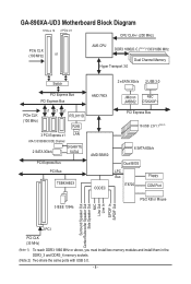
GA-890XA-UD3 Motherboard Block Diagram 1 PCIe x 16 2 PCIe x 8 CPU CLK+/- (200 MHz) PCIe CLK (100 MHz) or...100 MHz) x1 x1 x1 RTL8111D RJ45 3 PCI Express x1 LAN ATA-133/100/66/33 IDE Channel 2 SATA 3Gb/s GIGABYTE SATA2 PCI Express Bus PCI Bus TSB43AB23 AMD 790X AMD SB850 CODEC JMicron NEC JMB362 D720200F1 PCI Express Bus 16 USB 2.0/1.1(Note... 2) 6 SATA 6Gb/s Dual BIOS LPC Bus IT8720 Floppy COM Port 3 IEEE 1394a PS/2 KB or Mouse Surround Speaker Out Center/Subwoofer Speaker Out Side...
GA-890XA-UD3 Motherboard Block Diagram 1 PCIe x 16 2 PCIe x 8 CPU CLK+/- (200 MHz) PCIe CLK (100 MHz) or...100 MHz) x1 x1 x1 RTL8111D RJ45 3 PCI Express x1 LAN ATA-133/100/66/33 IDE Channel 2 SATA 3Gb/s GIGABYTE SATA2 PCI Express Bus PCI Bus TSB43AB23 AMD 790X AMD SB850 CODEC JMicron NEC JMB362 D720200F1 PCI Express Bus 16 USB 2.0/1.1(Note... 2) 6 SATA 6Gb/s Dual BIOS LPC Bus IT8720 Floppy COM Port 3 IEEE 1394a PS/2 KB or Mouse Surround Speaker Out Center/Subwoofer Speaker Out Side...
Manual
Page 12
... memory size displayed will operate at up to x8 mode. (Note 4) Two share the same ports with the PCIEX16 slot. Hardware Installation - 12 - Hardware Monitor w w w w w w BIOS w w w w Unique Features w w w w w w w w w w w Bundled Software w System voltage detection CPU/System temperature detection CPU/System/Power fan speed detection CPU overheating warning CPU/System/Power fan fail...
... memory size displayed will operate at up to x8 mode. (Note 4) Two share the same ports with the PCIEX16 slot. Hardware Installation - 12 - Hardware Monitor w w w w w w BIOS w w w w Unique Features w w w w w w w w w w w Bundled Software w System voltage detection CPU/System temperature detection CPU/System/Power fan speed detection CPU overheating warning CPU/System/Power fan fail...
Manual
Page 16
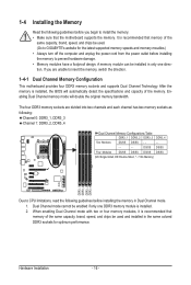
... memory speeds and momery moudles.) • Always turn off the computer and unplug the power cord from the power outlet before installing the memory to GIGABYTE's website for optimum performance. It is installed, the BIOS will double the original memory bandwidth.
... memory speeds and momery moudles.) • Always turn off the computer and unplug the power cord from the power outlet before installing the memory to GIGABYTE's website for optimum performance. It is installed, the BIOS will double the original memory bandwidth.
Manual
Page 18
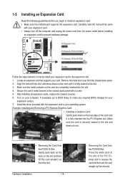
... PCIEX8 Slot: Press the white latch at the end of the card until it is securely seated in the expansion slot. 1. If necessary, go to BIOS Setup to install an expansion card: • Make sure the motherboard supports the expansion card. Remove the metal slot cover from the slot. Turn on... the slot and then lift the card straight out from the power outlet before you begin to make any required BIOS changes for your expansion card in the slot and does not rock. • Removing the Card from the PCIEX16 Slot: Gently push back on the...
... PCIEX8 Slot: Press the white latch at the end of the card until it is securely seated in the expansion slot. 1. If necessary, go to BIOS Setup to install an expansion card: • Make sure the motherboard supports the expansion card. Remove the metal slot cover from the slot. Turn on... the slot and then lift the card straight out from the power outlet before you begin to make any required BIOS changes for your expansion card in the slot and does not rock. • Removing the Card from the PCIEX16 Slot: Gently push back on the...
Manual
Page 26
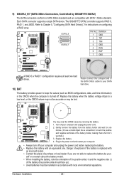
...of the SATA 3Gb/s cable to your SATA hard drive. 10) BAT The battery provides power to keep the values (such as BIOS configurations, date, and time information) in the CMOS when the computer is replaced with an equivalent one minute. (Or use a metal.... 2. Danger of purchase or local dealer if you are compatible with local environmental regulations. Hardware Installation - 26 - Each SATA connector supports a single SATA device. The GIGABYTE SATA2 controller supports RAID 0, RAID 1, and JBOD. G.QBOFM GSATA2_6 7 7 GSATA2_7 Pin No. 1 2 3 4 5 6 7 Definition GND TXP TXN GND RXN RXP ...
...of the SATA 3Gb/s cable to your SATA hard drive. 10) BAT The battery provides power to keep the values (such as BIOS configurations, date, and time information) in the CMOS when the computer is replaced with an equivalent one minute. (Or use a metal.... 2. Danger of purchase or local dealer if you are compatible with local environmental regulations. Hardware Installation - 26 - Each SATA connector supports a single SATA device. The GIGABYTE SATA2 controller supports RAID 0, RAID 1, and JBOD. G.QBOFM GSATA2_6 7 7 GSATA2_7 Pin No. 1 2 3 4 5 6 7 Definition GND TXP TXN GND RXN RXP ...

Manual
Page 27
...Connects to the power status indicator on the chassis front panel. The system reports system startup status by chassis. If a problem is detected, the BIOS may differ by issuing a beep code. The LED is on when the hard drive is reading or writing data. • RES (Reset ...has been removed. This function requires a chassis with a chassis intrusion switch/sensor. When connecting your system using the power switch (refer to Chapter 2, "BIOS Setup," "Power Management Setup," for information about beep codes. • HD (Hard Drive Activity LED, Blue) Connects to the reset switch on the...
...Connects to the power status indicator on the chassis front panel. The system reports system startup status by chassis. If a problem is detected, the BIOS may differ by issuing a beep code. The LED is on when the hard drive is reading or writing data. • RES (Reset ...has been removed. This function requires a chassis with a chassis intrusion switch/sensor. When connecting your system using the power switch (refer to Chapter 2, "BIOS Setup," "Power Management Setup," for information about beep codes. • HD (Hard Drive Activity LED, Blue) Connects to the reset switch on the...
Manual
Page 31
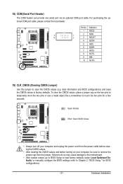
... and before turning on the two pins to temporarily short the two pins or use a metal object like a screwdriver to touch the two pins for BIOS configurations). - 31 - Definition 1 NDCD- 9 1 2 NSIN 10 2 3 NSOUT 4 NDTR- 5 GND 6 NDSR- 7 NRTS- 8 NCTS- 9 NRI- 10 No Pin 19...) CLR_CMOS (Clearing CMOS Jumper) Use this jumper to factory defaults. date information and BIOS configurations) and reset the CMOS values to clear the CMOS values (e.g. Hardware Installation To clear the CMOS values, place a jumper cap on your computer and...
... and before turning on the two pins to temporarily short the two pins or use a metal object like a screwdriver to touch the two pins for BIOS configurations). - 31 - Definition 1 NDCD- 9 1 2 NSIN 10 2 3 NSOUT 4 NDTR- 5 GND 6 NDSR- 7 NRTS- 8 NCTS- 9 NRI- 10 No Pin 19...) CLR_CMOS (Clearing CMOS Jumper) Use this jumper to factory defaults. date information and BIOS configurations) and reset the CMOS values to clear the CMOS values (e.g. Hardware Installation To clear the CMOS values, place a jumper cap on your computer and...
Manual
Page 33
...Chapter 5, "Troubleshooting," for how to Chapter 4, "BIOS Update Utilities." • Because BIOS flashing is recommended that you need to) to activate certain system features. BIOS Setup To upgrade the BIOS, use either the GIGABYTE Q-Flash or @BIOS utility. • Q-Flash allows the user to keep... the configuration values in system malfunction. • BIOS will emit a beep code during system startup,...
...Chapter 5, "Troubleshooting," for how to Chapter 4, "BIOS Update Utilities." • Because BIOS flashing is recommended that you need to) to activate certain system features. BIOS Setup To upgrade the BIOS, use either the GIGABYTE Q-Flash or @BIOS utility. • Q-Flash allows the user to keep... the configuration values in system malfunction. • BIOS will emit a beep code during system startup,...
Manual
Page 34
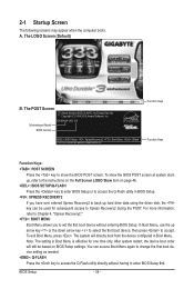
..., Inc. After system restart, the device boot order will directly boot from the device configured in Boot Menu. The LOGO Screen (Default) B. Motherboard Model BIOS Version GA-890XA-UD3 E9 . . . . : BIOS Setup : XpressRecovery2 : Boot Menu : Qflash 01/27/2010-RD780-SB850-7A66CG03C-00 Function Keys Function Keys Function Keys: : POST SCREEN Press the key to...
..., Inc. After system restart, the device boot order will directly boot from the device configured in Boot Menu. The LOGO Screen (Default) B. Motherboard Model BIOS Version GA-890XA-UD3 E9 . . . . : BIOS Setup : XpressRecovery2 : Boot Menu : Qflash 01/27/2010-RD780-SB850-7A66CG03C-00 Function Keys Function Keys Function Keys: : POST SCREEN Press the key to...
Manual
Page 35
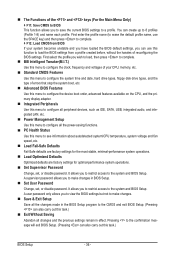
... Program Function Keys Move the selection bar to select an item Execute command or enter the submenu Main Menu: Exit the BIOS Setup program Submenus: Exit current submenu Increase the numeric value or make changes Decrease the numeric value or make changes Show descriptions of... Setup Exit Without Saving ESC: Quit F8: Q-Flash Select Item F10: Save & Exit Setup Change CPU's Clock & Voltage F11: Save CMOS to BIOS F12: Load CMOS from BIOS Main Menu Help The on-screen description of a highlighted setup option is in the Item Help block on the right side of function...
... Program Function Keys Move the selection bar to select an item Execute command or enter the submenu Main Menu: Exit the BIOS Setup program Submenus: Exit current submenu Increase the numeric value or make changes Decrease the numeric value or make changes Show descriptions of... Setup Exit Without Saving ESC: Quit F8: Q-Flash Select Item F10: Save & Exit Setup Change CPU's Clock & Voltage F11: Save CMOS to BIOS F12: Load CMOS from BIOS Main Menu Help The on-screen description of a highlighted setup option is in the Item Help block on the right side of function...
Manual
Page 36
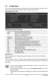
...time and date, hard drive types, floppy disk drive types, and the type of errors that stop the system boot, etc. Advanced BIOS Features Use this menu to configure the device boot order, advanced features available on the CPU, and the primary display adapter. Integrated Peripherals...menu to configure all the power-saving functions. PC Health Status Use this function to load the BIOS settings from BIOS If your system becomes unstable and you have loaded the BIOS default settings, you to make changes. Save & Exit Setup Save all changes and the previous ...
...time and date, hard drive types, floppy disk drive types, and the type of errors that stop the system boot, etc. Advanced BIOS Features Use this menu to configure the device boot order, advanced features available on the CPU, and the primary display adapter. Integrated Peripherals...menu to configure all the power-saving functions. PC Health Status Use this function to load the BIOS settings from BIOS If your system becomes unstable and you have loaded the BIOS default settings, you to make changes. Save & Exit Setup Save all changes and the previous ...
Manual
Page 37
... occurs, clear the CMOS values and reset the board to default values.) • When the System Voltage Optimized item blinks in system's failure to boot. BIOS Setup This page is for advanced users only and we recommend you not to alter the default settings to prevent system instability or other unexpected...
... occurs, clear the CMOS values and reset the board to default values.) • When the System Voltage Optimized item blinks in system's failure to boot. BIOS Setup This page is for advanced users only and we recommend you not to alter the default settings to prevent system instability or other unexpected...
Manual
Page 38
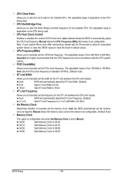
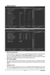
... to boot after overclocking, please wait for 20 seconds to allow for the installed CPU. Important It is dependent on the CPU being used . Auto BIOS will automatically adjust the HT Link Width. (Default) 8 bit Sets HT Link Width to 8 bit. 16 bit Sets HT Link Width to 16 bit. ... range is highly recommended that the CPU frequency be configurable. CPU Host Clock Control Enables or disables the control of CPU host clock. Auto BIOS will automatically adjust the HT Link Frequency. (Default) x1~x13 Sets HT Link Frequency to automatically adjust the CPU host frequency...
... to boot after overclocking, please wait for 20 seconds to allow for the installed CPU. Important It is dependent on the CPU being used . Auto BIOS will automatically adjust the HT Link Width. (Default) 8 bit Sets HT Link Width to 8 bit. 16 bit Sets HT Link Width to 16 bit. ... range is highly recommended that the CPU frequency be configurable. CPU Host Clock Control Enables or disables the control of CPU host clock. Auto BIOS will automatically adjust the HT Link Frequency. (Default) x1~x13 Sets HT Link Frequency to automatically adjust the CPU host frequency...
Manual
Page 39
... Important It is from 200 MHz to automatically adjust the CPU host frequency. Auto (default) allows the BIOS to 500 MHz. The adjustable range is highly recommended that the CPU frequency be configurable. (Default: Auto) - 39 - Manual allows the memory clock control item ...
... Important It is from 200 MHz to automatically adjust the CPU host frequency. Auto (default) allows the BIOS to 500 MHz. The adjustable range is highly recommended that the CPU frequency be configurable. (Default: Auto) - 39 - Manual allows the memory clock control item ...

Manual
Page 40
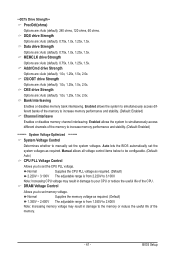
...), 4T~7T. RAS to Manual. Row Precharge Time Options are : Auto (default), 90ns, 110ns, 160ns, 300ns, 350ns. Trfc1 for DIMM4 Options are : Auto (default), Manual. BIOS Setup - 40 -
...), 4T~7T. RAS to Manual. Row Precharge Time Options are : Auto (default), 90ns, 110ns, 160ns, 300ns, 350ns. Trfc1 for DIMM4 Options are : Auto (default), Manual. BIOS Setup - 40 -
Manual
Page 41
..., 1.5x, 2.0x. Enabled allows the system to simultaneously access different channels of the memory to 2.400V. Auto lets the BIOS automatically set memory voltage. Normal Supplies the CPU PLL voltage as required. Note: Increasing memory voltage may result in damage to set...drive Strength Options are : Auto (default), 1.0x, 1.25x, 1.5x, 2.0x. Bank Interleaving Enables or disables memory bank interleaving. BIOS Setup Enabled allows the system to simultaneously access different banks of the memory to increase memory performance and stability. (Default: Enabled) ******** ...
..., 1.5x, 2.0x. Enabled allows the system to simultaneously access different channels of the memory to 2.400V. Auto lets the BIOS automatically set memory voltage. Normal Supplies the CPU PLL voltage as required. Note: Increasing memory voltage may result in damage to set...drive Strength Options are : Auto (default), 1.0x, 1.25x, 1.5x, 2.0x. Bank Interleaving Enables or disables memory bank interleaving. BIOS Setup Enabled allows the system to simultaneously access different banks of the memory to increase memory performance and stability. (Default: Enabled) ******** ...
Manual
Page 42
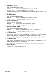
... from 1.450V to set the CPU voltage. NB/PCIe/PLL Voltage Control Allows you to your CPU or reduce the useful life of the CPU. BIOS Setup - 42 - The adjustable range is dependent on the CPU being installed. (Default: Normal) Note: Increasing CPU voltage may result in damage to the memory...
... from 1.450V to set the CPU voltage. NB/PCIe/PLL Voltage Control Allows you to your CPU or reduce the useful life of the CPU. BIOS Setup - 42 - The adjustable range is dependent on the CPU being installed. (Default: Normal) Note: Increasing CPU voltage may result in damage to the memory...


