
Manual
Page 3
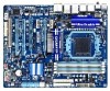
... in this manual may be reproduced, copied, translated, transmitted, or published in this product, GIGABYTE provides the following types of documentations: For quick set-up of GIGABYTE. Documentation Classifications In order to assist in this : "REV: X.X." Copyright © 2011 GIGA... Check your motherboard looks like this manual is protected by GIGABYTE without GIGABYTE's prior written permission. All rights reserved. For product-related information, check on our website at: http://www.gigabyte.com Identifying Your Motherboard Revision The revision number on your ...
... in this manual may be reproduced, copied, translated, transmitted, or published in this product, GIGABYTE provides the following types of documentations: For quick set-up of GIGABYTE. Documentation Classifications In order to assist in this : "REV: X.X." Copyright © 2011 GIGA... Check your motherboard looks like this manual is protected by GIGABYTE without GIGABYTE's prior written permission. All rights reserved. For product-related information, check on our website at: http://www.gigabyte.com Identifying Your Motherboard Revision The revision number on your ...
Manual
Page 4
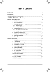
Table of Contents Box Contents...6 Optional Items...6 GA-890FXA-UD5 Motherboard Layout 7 GA-890FXA-UD5 Motherboard Block Diagram 8 Chapter 1 Hardware Installation 9 1-1 Installation Precautions 9 1-2 Product Specifications 10 1-3 Installing the CPU and CPU ...™ Configuration 19 1-7 Back Panel Connectors 20 1-8 Internal Connectors 22 Chapter 2 BIOS Setup 35 2-1 Startup Screen 36 2-2 The Main Menu 37 2-3 MB Intelligent Tweaker(M.I.T 39 2-4 Standard CMOS Features 45 2-5 Advanced BIOS Features 47 2-6 Integrated Peripherals 49 2-7 Power Management Setup 53 2-8 PC Health Status...
Table of Contents Box Contents...6 Optional Items...6 GA-890FXA-UD5 Motherboard Layout 7 GA-890FXA-UD5 Motherboard Block Diagram 8 Chapter 1 Hardware Installation 9 1-1 Installation Precautions 9 1-2 Product Specifications 10 1-3 Installing the CPU and CPU ...™ Configuration 19 1-7 Back Panel Connectors 20 1-8 Internal Connectors 22 Chapter 2 BIOS Setup 35 2-1 Startup Screen 36 2-2 The Main Menu 37 2-3 MB Intelligent Tweaker(M.I.T 39 2-4 Standard CMOS Features 45 2-5 Advanced BIOS Features 47 2-6 Integrated Peripherals 49 2-7 Power Management Setup 53 2-8 PC Health Status...

Manual
Page 5
... Utilities...64 Chapter 4 Unique Features 65 4-1 Xpress Recovery2 65 4-2 BIOS Update Utilities 68 4-2-1 Updating the BIOS with the Q-Flash Utility 68 4-2-2 Updating the BIOS with the @BIOS Utility 71 4-3 EasyTune 6...72 4-4 Easy Energy Saver 73 4-5 Q-...Share...75 4-6 SMART Recovery 76 4-7 Auto Green...77 4-8 Teaming 78 Chapter 5 Appendix...79 5-1 Configuring SATA Hard Drive(s 79 5-1-1 Configuring AMD SB850 SATA Controller 79 5-1-2 Configuring GIGABYTE...
... Utilities...64 Chapter 4 Unique Features 65 4-1 Xpress Recovery2 65 4-2 BIOS Update Utilities 68 4-2-1 Updating the BIOS with the Q-Flash Utility 68 4-2-2 Updating the BIOS with the @BIOS Utility 71 4-3 EasyTune 6...72 4-4 Easy Energy Saver 73 4-5 Q-...Share...75 4-6 SMART Recovery 76 4-7 Auto Green...77 4-8 Teaming 78 Chapter 5 Appendix...79 5-1 Configuring SATA Hard Drive(s 79 5-1-1 Configuring AMD SB850 SATA Controller 79 5-1-2 Configuring GIGABYTE...
Manual
Page 8
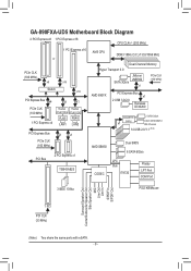
GA-890FXA-UD5 Motherboard Block Diagram 2 PCI Express x8 1 PCI Express x16 CPU CLK+/- (200 MHz) 1 PCI Express x16 or PCIe CLK (100 MHz) x8 x16 Switch x16 ... SATA 3Gb/s x1 PCIe CLK (100 MHz) AMD 890FX PCI Express Bus x1 2 USB 3.0/2.0 Renesas D720200 GIGABYTE x1 SATA2 2 SATA 3Gb/s ATA-133/100/66/33 IDE Channel 14 USB 2.0/1.1 (Note) AMD SB850 Dual BIOS 6 SATA 6Gb/s CODEC LPC Bus IT8720 Floppy LPT Port COM Port 3 IEEE 1394a PS/2 KB/Mouse Surround...
GA-890FXA-UD5 Motherboard Block Diagram 2 PCI Express x8 1 PCI Express x16 CPU CLK+/- (200 MHz) 1 PCI Express x16 or PCIe CLK (100 MHz) x8 x16 Switch x16 ... SATA 3Gb/s x1 PCIe CLK (100 MHz) AMD 890FX PCI Express Bus x1 2 USB 3.0/2.0 Renesas D720200 GIGABYTE x1 SATA2 2 SATA 3Gb/s ATA-133/100/66/33 IDE Channel 14 USB 2.0/1.1 (Note) AMD SB850 Dual BIOS 6 SATA 6Gb/s CODEC LPC Bus IT8720 Floppy LPT Port COM Port 3 IEEE 1394a PS/2 KB/Mouse Surround...

Manual
Page 12
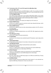
...flash ŠŠ Use of licensed AWARD BIOS ŠŠ Support for DualBIOS™ ŠŠ PnP 1.0a, DMI 2.0, SM BIOS 2.4, ACPI 1.0b Unique Features ŠŠ Support for @BIOS ŠŠ Support for Q-Flash ŠŠ Support for Xpress BIOS Rescue ŠŠ Support for Download Center...138;Š Support for Microsoft® Windows 7/Vista/XP Form Factor ŠŠ ATX Form Factor; 30.5cm x 24.4cm * GIGABYTE reserves the right to make any changes to the product specifications and product-related information without prior notice. Hardware Installation - 12 - Back...
...flash ŠŠ Use of licensed AWARD BIOS ŠŠ Support for DualBIOS™ ŠŠ PnP 1.0a, DMI 2.0, SM BIOS 2.4, ACPI 1.0b Unique Features ŠŠ Support for @BIOS ŠŠ Support for Q-Flash ŠŠ Support for Xpress BIOS Rescue ŠŠ Support for Download Center...138;Š Support for Microsoft® Windows 7/Vista/XP Form Factor ŠŠ ATX Form Factor; 30.5cm x 24.4cm * GIGABYTE reserves the right to make any changes to the product specifications and product-related information without prior notice. Hardware Installation - 12 - Back...

Manual
Page 16
.../SS Four Modules DS/SS DS/SS DS/SS DS/SS (SS=Single-Sided, DS=Double-Sided, "- -"=No Memory) DDR3_1 DDR3_2 DDR3_3 DDR3_4 Due to GIGABYTE's website for optimum performance. 1-4 Installing the Memory Read the following guidelines before you are divided into two channels and each channel has two memory sockets... provides four DDR3 memory sockets and supports Dual Channel Technology. When enabling Dual Channel mode with two or four memory modules, it is installed, the BIOS will double the original memory bandwidth.
.../SS Four Modules DS/SS DS/SS DS/SS DS/SS (SS=Single-Sided, DS=Double-Sided, "- -"=No Memory) DDR3_1 DDR3_2 DDR3_3 DDR3_4 Due to GIGABYTE's website for optimum performance. 1-4 Installing the Memory Read the following guidelines before you are divided into two channels and each channel has two memory sockets... provides four DDR3 memory sockets and supports Dual Channel Technology. When enabling Dual Channel mode with two or four memory modules, it is installed, the BIOS will double the original memory bandwidth.

Manual
Page 18
... straight up from the power outlet before you begin to correctly install your expansion card in your expansion card(s). 7. If necessary, go to BIOS Setup to prevent hardware damage. Example: Installing and Removing a PCI Express Graphics Card: • Installing a Graphics Card: Gently push down ...card in the expansion slot. 1. 1-5 Installing an Expansion Card Read the following guidelines before installing an expansion card to make any required BIOS changes for your operating system. Locate an expansion slot that came with a screw. 5. Make sure the card is fully seated in...
... straight up from the power outlet before you begin to correctly install your expansion card in your expansion card(s). 7. If necessary, go to BIOS Setup to prevent hardware damage. Example: Installing and Removing a PCI Express Graphics Card: • Installing a Graphics Card: Gently push down ...card in the expansion slot. 1. 1-5 Installing an Expansion Card Read the following guidelines before installing an expansion card to make any required BIOS changes for your operating system. Locate an expansion slot that came with a screw. 5. Make sure the card is fully seated in...

Manual
Page 27
...off (S5). • PW (Power Switch, Red): Connects to the pin assignments below. When connecting your system using the power switch (refer to Chapter 2, "BIOS Setup," "Power Management Setup," for information about beep codes. • HD (Hard Drive Activity LED, Blue) Connects to the power status indicator on the chassis...panel module to the chassis intrusion switch/sensor on the chassis front panel. The LED is on when the hard drive is detected, the BIOS may configure the way to turn off when the system is on the chassis to this header, make sure the wire assignments and the ...
...off (S5). • PW (Power Switch, Red): Connects to the pin assignments below. When connecting your system using the power switch (refer to Chapter 2, "BIOS Setup," "Power Management Setup," for information about beep codes. • HD (Hard Drive Activity LED, Blue) Connects to the power status indicator on the chassis...panel module to the chassis intrusion switch/sensor on the chassis front panel. The LED is on when the hard drive is detected, the BIOS may configure the way to turn off when the system is on the chassis to this header, make sure the wire assignments and the ...

Manual
Page 32
...few seconds. 20) BAT (Battery) The battery provides power to factory defaults. Replace the battery. 4. date information and BIOS configurations) and reset the CMOS values to keep the values (such as BIOS configurations, date, and time information) in the CMOS when the computer is replaced with an incorrect model. • ... your computer. • Always turn off . Plug in accordance with an equivalent one minute. (Or use a metal object like a screwdriver to Chapter 2, "BIOS Setup," for 5 seconds.) 3. To clear the CMOS values, place a jumper cap on your computer, be lost.
...few seconds. 20) BAT (Battery) The battery provides power to factory defaults. Replace the battery. 4. date information and BIOS configurations) and reset the CMOS values to keep the values (such as BIOS configurations, date, and time information) in the CMOS when the computer is replaced with an incorrect model. • ... your computer. • Always turn off . Plug in accordance with an equivalent one minute. (Or use a metal object like a screwdriver to Chapter 2, "BIOS Setup," for 5 seconds.) 3. To clear the CMOS values, place a jumper cap on your computer, be lost.

Manual
Page 33
... 3 quick buttons: power button, clearing CMOS button and reset button. Use the clearing CMOS button to Chapter 2, "BIOS Setup," for BIOS configurations). - 33 - date information and BIOS configurations) and reset the CMOS values to factory defaults when needed. • Always turn on/off your computer and ...from the power outlet before clearing the CMOS values. • After system restart, go to BIOS Setup to load factory defaults (select Load Optimized Defaults) or manually configure the BIOS settings (refer to clear the CMOS values (e.g. The power button and reset button allow users ...
... 3 quick buttons: power button, clearing CMOS button and reset button. Use the clearing CMOS button to Chapter 2, "BIOS Setup," for BIOS configurations). - 33 - date information and BIOS configurations) and reset the CMOS values to factory defaults when needed. • Always turn on/off your computer and ...from the power outlet before clearing the CMOS values. • After system restart, go to BIOS Setup to load factory defaults (select Load Optimized Defaults) or manually configure the BIOS settings (refer to clear the CMOS values (e.g. The power button and reset button allow users ...
Manual
Page 35
...hardware parameters of the system in the main menu of the BIOS Setup program. BIOS includes a BIOS Setup program that you do it is turned off, the battery on the motherboard. To upgrade the BIOS, use either the GIGABYTE Q-Flash or @BIOS utility. • Q-Flash allows the user to boot. If... in the CMOS on the motherboard supplies the necessary power to the CMOS to Chapter 4, "BIOS Update Utilities." • Because BIOS flashing is potentially risky, if you not flash the BIOS. When the power is recommended that allows the user to modify basic system configuration settings or...
...hardware parameters of the system in the main menu of the BIOS Setup program. BIOS includes a BIOS Setup program that you do it is turned off, the battery on the motherboard. To upgrade the BIOS, use either the GIGABYTE Q-Flash or @BIOS utility. • Q-Flash allows the user to boot. If... in the CMOS on the motherboard supplies the necessary power to the CMOS to Chapter 4, "BIOS Update Utilities." • Because BIOS flashing is potentially risky, if you not flash the BIOS. When the power is recommended that allows the user to modify basic system configuration settings or...
Manual
Page 36
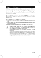
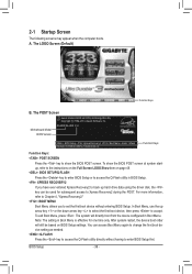
... for subsequent access to accept. BIOS Setup - 36 - To exit Boot Menu, press . The POST Screen Award Modular BIOS v6.00PG, An Energy Star Ally Copyright (C) 1984-2010, Award Software, Inc. Motherboard Model BIOS Version GA-890FXA-UD5 F3c . . . . : BIOS Setup : XpressRecovery2 : Boot Menu... : Qflash 05/24/2010-RD890-SB850-7A66DG04C-00 Function Keys Function Keys: : POST SCREEN Press the key to show the BIOS POST screen at system startup, refer ...
... for subsequent access to accept. BIOS Setup - 36 - To exit Boot Menu, press . The POST Screen Award Modular BIOS v6.00PG, An Energy Star Ally Copyright (C) 1984-2010, Award Software, Inc. Motherboard Model BIOS Version GA-890FXA-UD5 F3c . . . . : BIOS Setup : XpressRecovery2 : Boot Menu... : Qflash 05/24/2010-RD890-SB850-7A66DG04C-00 Function Keys Function Keys: : POST SCREEN Press the key to show the BIOS POST screen at system startup, refer ...

Manual
Page 37
...for the current submenus Access the Q-Flash utility Display system information Save all the changes and exit the BIOS Setup program Save CMOS to BIOS Load CMOS from BIOS BIOS Setup Program Function Keys Move the selection bar to select an item Execute command or enter the submenu...numeric value or make changes Decrease the numeric value or make changes Show descriptions of the function keys Move cursor to BIOS F12: Load CMOS from BIOS Main Menu Help The on-screen description of a highlighted setup option is displayed on the right (submenus only) ...
...for the current submenus Access the Q-Flash utility Display system information Save all the changes and exit the BIOS Setup program Save CMOS to BIOS Load CMOS from BIOS BIOS Setup Program Function Keys Move the selection bar to select an item Execute command or enter the submenu...numeric value or make changes Decrease the numeric value or make changes Show descriptions of the function keys Move cursor to BIOS F12: Load CMOS from BIOS Main Menu Help The on-screen description of a highlighted setup option is displayed on the right (submenus only) ...
Manual
Page 38
...1-8) and name each profile. A user password only allows you wish to load, then press to complete. MB Intelligent Tweaker(M.I.T.) Use this task.) BIOS Setup - 38 - It allows you can also carry out this menu to configure the clock, frequency and voltages of your system becomes unstable and you... and date, hard drive types, floppy disk drive types, and the type of errors that stop the system boot, etc. Advanced BIOS Features Use this menu to configure the device boot order, advanced features available on the CPU, and the primary display adapter. Integrated ...
...1-8) and name each profile. A user password only allows you wish to load, then press to complete. MB Intelligent Tweaker(M.I.T.) Use this task.) BIOS Setup - 38 - It allows you can also carry out this menu to configure the clock, frequency and voltages of your system becomes unstable and you... and date, hard drive types, floppy disk drive types, and the type of errors that stop the system boot, etc. Advanced BIOS Features Use this menu to configure the device boot order, advanced features available on the CPU, and the primary display adapter. Integrated ...

Manual
Page 39
... ESC: Exit F1: General Help F7: Optimized Defaults CMOS Setup Utility-Copyright (C) 1984-2010 Award Software MB Intelligent Tweaker(M.I .T.) CPU Clock Ratio CPU NorthBridge Freq. BIOS Setup Incorrectly doing overclock/overvoltage may result in system's failure to boot. If this occurs, clear the CMOS values and reset the board to default...
... ESC: Exit F1: General Help F7: Optimized Defaults CMOS Setup Utility-Copyright (C) 1984-2010 Award Software MB Intelligent Tweaker(M.I .T.) CPU Clock Ratio CPU NorthBridge Freq. BIOS Setup Incorrectly doing overclock/overvoltage may result in system's failure to boot. If this occurs, clear the CMOS values and reset the board to default...

Manual
Page 40
The adjustable range is from 100 MHz to 200 MHz. Auto BIOS will automatically adjust the HT Link Frequency. (Default) x1~x10 Sets HT Link Frequency to x1~x10 (200 MHz~2.0 GHz). Auto BIOS will automatically adjust the HT Link Width. (Default) 8 bit Sets HT Link Width to 8 bit. 16 bit... Sets HT Link Width to 16 bit. Auto lets BIOS automatically set the memory clock. BIOS Setup - 40 - Auto (default) allows the BIOS to X4.00. Note: If your system fails to boot after overclocking, please wait for 20 seconds to allow for...
The adjustable range is from 100 MHz to 200 MHz. Auto BIOS will automatically adjust the HT Link Frequency. (Default) x1~x10 Sets HT Link Frequency to x1~x10 (200 MHz~2.0 GHz). Auto BIOS will automatically adjust the HT Link Width. (Default) 8 bit Sets HT Link Width to 8 bit. 16 bit... Sets HT Link Width to 16 bit. Auto lets BIOS automatically set the memory clock. BIOS Setup - 40 - Auto (default) allows the BIOS to X4.00. Note: If your system fails to boot after overclocking, please wait for 20 seconds to allow for...

Manual
Page 41
... allows all DDR3 Timing items below to set memory control mode. DCTs Mode Allows you to be configurable. Auto 5T 5T Auto 90ns 90ns Auto -- -- BIOS Setup DRAM Configuration CMOS Setup Utility-Copyright (C) 1984-2010 Award Software DRAM Configuration CPU Host Clock Control x CPU Frequency(MHz) Set Memory Clock x Memory Clock...
... allows all DDR3 Timing items below to set memory control mode. DCTs Mode Allows you to be configurable. Auto 5T 5T Auto 90ns 90ns Auto -- -- BIOS Setup DRAM Configuration CMOS Setup Utility-Copyright (C) 1984-2010 Award Software DRAM Configuration CPU Host Clock Control x CPU Frequency(MHz) Set Memory Clock x Memory Clock...

Manual
Page 42
..., 350ns. Trfc3 for DIMM3 Options are : Auto (default), 90ns, 110ns, 160ns, 300ns, 350ns. RAS to CAS R/W Delay Options are : Auto (default), 0.75x, 1.0x, 1.25x, 1.5x. BIOS Setup - 42 -
..., 350ns. Trfc3 for DIMM3 Options are : Auto (default), 90ns, 110ns, 160ns, 300ns, 350ns. RAS to CAS R/W Delay Options are : Auto (default), 0.75x, 1.0x, 1.25x, 1.5x. BIOS Setup - 42 -

Manual
Page 43
...PLL Voltage Control Allows you to set the memory to power down mode when the CKE pin is from 2.220V to set memory voltage. BIOS Setup DRAM Voltage Control Allows you to 1.050V. DDR VTT Voltage Control Allows you to set the system voltages as required. (Default)... CPU PLL voltage. Bank Interleaving Enables or disables memory bank interleaving. Normal Supplies the memory VTT voltage as required. Auto lets the BIOS automatically set the memory VTT voltage. Note: Increasing CPU voltage may result in damage to increase memory performance and stability. (Default: ...
...PLL Voltage Control Allows you to set the memory to power down mode when the CKE pin is from 2.220V to set memory voltage. BIOS Setup DRAM Voltage Control Allows you to 1.050V. DDR VTT Voltage Control Allows you to set the system voltages as required. (Default)... CPU PLL voltage. Bank Interleaving Enables or disables memory bank interleaving. Normal Supplies the memory VTT voltage as required. Auto lets the BIOS automatically set the memory VTT voltage. Note: Increasing CPU voltage may result in damage to increase memory performance and stability. (Default: ...

Manual
Page 44
... Bridge voltage. Auto sets the CPU voltage as required. NB Voltage Control Allows you to your CPU. The adjustable range is from 0.900V to 2.100V. BIOS Setup - 44 - Normal Supplies the North Bridge voltage as required. (Default) 0.900V ~ 1.450V The adjustable range is dependent on the CPU being installed. (Default: Normal...
... Bridge voltage. Auto sets the CPU voltage as required. NB Voltage Control Allows you to your CPU. The adjustable range is from 0.900V to 2.100V. BIOS Setup - 44 - Normal Supplies the North Bridge voltage as required. (Default) 0.900V ~ 1.450V The adjustable range is dependent on the CPU being installed. (Default: Normal...


