Manual
Page 3
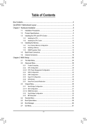
......4 GA-6PXSV1 Motherboard Layout 5 Chapter 1 Hardware Installation 8 1-1 Installation Precautions 8 1-2 Product Specifications 9 1-3 Installing the CPU and CPU Cooler 11 1-3-1 Installing the CPU...11 1-3-2 Installing the CPU Cooler 13 1-4 Installing the Memory 14 1-4-1 Four Channel Memory Configuration 14 1-4-2 Installing a Memory 15 1-4-3 DIMM Population Table 15 1-5 Back Panel Connectors 16 1-6 Internal Connectors 18 Chapter 2 BIOS Setup...
......4 GA-6PXSV1 Motherboard Layout 5 Chapter 1 Hardware Installation 8 1-1 Installation Precautions 8 1-2 Product Specifications 9 1-3 Installing the CPU and CPU Cooler 11 1-3-1 Installing the CPU...11 1-3-2 Installing the CPU Cooler 13 1-4 Installing the Memory 14 1-4-1 Four Channel Memory Configuration 14 1-4-2 Installing a Memory 15 1-4-3 DIMM Population Table 15 1-5 Back Panel Connectors 16 1-6 Internal Connectors 18 Chapter 2 BIOS Setup...

Manual
Page 6
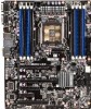
... System fan cable connectors Mini SAS connector Front USB 3.0 connector Front USB 3.0 connector PCI slot (32bit/33MHz) TPM module IEEE 1394 connector BIOS write protect jumper ME recovery jumper BIOS recovery jumper Clear password jumper Front Audio connector SPDIF header PCI-E slot 4 (x4 slot) PCI-E slot 3 (x8 slot) PCI-E slot 2 (x16 slot...
... System fan cable connectors Mini SAS connector Front USB 3.0 connector Front USB 3.0 connector PCI slot (32bit/33MHz) TPM module IEEE 1394 connector BIOS write protect jumper ME recovery jumper BIOS recovery jumper Clear password jumper Front Audio connector SPDIF header PCI-E slot 4 (x4 slot) PCI-E slot 3 (x8 slot) PCI-E slot 2 (x16 slot...

Manual
Page 9
Hardware Installation Back Panel Connectors I/O Controller Hardware Monitor BIOS ŠŠ 6 x USB 2.0/1.1 ports ŠŠ 1 x RJ-45 port ŠŠ 1 x IEEE 1394 port ŠŠ 6 x Audio ports (4 x Line-out/ 1 x Line-in/ 1 x MIC) ŠŠ 2 ... control function is supported will depend on the CPU/system cooler you install. ŠŠ 1 x 64 Mbit flash ŠŠ AMI BIOS Form Factor ŠŠ ATX Form Factor; 12 inch x 9.6 inch * GIGABYTE reserves the right to make any changes to the product specifications and product-related information without prior notice. - 9 -
Hardware Installation Back Panel Connectors I/O Controller Hardware Monitor BIOS ŠŠ 6 x USB 2.0/1.1 ports ŠŠ 1 x RJ-45 port ŠŠ 1 x IEEE 1394 port ŠŠ 6 x Audio ports (4 x Line-out/ 1 x Line-in/ 1 x MIC) ŠŠ 2 ... control function is supported will depend on the CPU/system cooler you install. ŠŠ 1 x 64 Mbit flash ŠŠ AMI BIOS Form Factor ŠŠ ATX Form Factor; 12 inch x 9.6 inch * GIGABYTE reserves the right to make any changes to the product specifications and product-related information without prior notice. - 9 -

Manual
Page 11
...installed in Four Channel mode. 1. When enabling Four Channel mode with two or four memory modules, it is installed, the BIOS will double the original memory bandwidth. 1-4 Installing the Memory Read the following guidelines before installing the memory in only one DDR3 ...the memory to prevent hardware damage. • Memory modules have a foolproof design. En- The eight DDR3 memory sockets are unable to GIGABYTE's website for optimum performance. - 11 - Hardware Installation After the memory is recommended that the motherboard supports the memory. A memory module ...
...installed in Four Channel mode. 1. When enabling Four Channel mode with two or four memory modules, it is installed, the BIOS will double the original memory bandwidth. 1-4 Installing the Memory Read the following guidelines before installing the memory in only one DDR3 ...the memory to prevent hardware damage. • Memory modules have a foolproof design. En- The eight DDR3 memory sockets are unable to GIGABYTE's website for optimum performance. - 11 - Hardware Installation After the memory is recommended that the motherboard supports the memory. A memory module ...

Manual
Page 28
... turn off your computer and unplug the power cord. 2. Turn off . Replace the battery when the battery voltage drops to keep the values (such as BIOS configurations, date, and time information) in the CMOS when the computer is replaced with an incorrect model. • Contact the place of purchase or local...
... turn off your computer and unplug the power cord. 2. Turn off . Replace the battery when the battery voltage drops to keep the values (such as BIOS configurations, date, and time information) in the CMOS when the computer is replaced with an incorrect model. • Contact the place of purchase or local...

Manual
Page 29
.... To clear the CMOS values, place a jumper cap on your computer, be sure to touch the two pins for BIOS configurations). - 29 - date information and BIOS configurations) and reset the CMOS values to clear the CMOS values (e.g. Failure to do so may cause damage to the... motherboard. • After system restart, go to BIOS Setup Exit menu and load factory defaults (select Load Default Values) or manually configure the BIOS settings (refer to Chapter 2, "BIOS Setup," for a few seconds. 1-2 Close: Normal operation (Default setting) 1 2-3 Close: Clear...
.... To clear the CMOS values, place a jumper cap on your computer, be sure to touch the two pins for BIOS configurations). - 29 - date information and BIOS configurations) and reset the CMOS values to clear the CMOS values (e.g. Failure to do so may cause damage to the... motherboard. • After system restart, go to BIOS Setup Exit menu and load factory defaults (select Load Default Values) or manually configure the BIOS settings (refer to Chapter 2, "BIOS Setup," for a few seconds. 1-2 Close: Normal operation (Default setting) 1 2-3 Close: Clear...

Manual
Page 30
Hardware Installation - 30 - 21) PASSWORD1 (Clearing Supervisor Password Jumper) 1 1-2 Close: Normal operation. (Default setting) 1 2-3 Close: Clear supervisor password. 22) BIOS_RVCR1 (BIOS Recovery Jumper) 1 1-2 Close: Normal operation. (Default setting) 1 2-3 Close: BIOS recovery mode.
Hardware Installation - 30 - 21) PASSWORD1 (Clearing Supervisor Password Jumper) 1 1-2 Close: Normal operation. (Default setting) 1 2-3 Close: Clear supervisor password. 22) BIOS_RVCR1 (BIOS Recovery Jumper) 1 1-2 Close: Normal operation. (Default setting) 1 2-3 Close: BIOS recovery mode.
Manual
Page 31
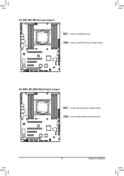
23) SSB_ME1 (ME Recovery Jumper) 1 1-2 Close: Enable ME recovery. 1 2-3 Close: Disable ME recovery. (Default setting) 24) BIOS_WP (BIOS Write Protect Jumper) 1 1-2 Close: Normal operation. (Default setting) 1 2-3 Close: Enable BIOS write protect function. - 31 - Hardware Installation
23) SSB_ME1 (ME Recovery Jumper) 1 1-2 Close: Enable ME recovery. 1 2-3 Close: Disable ME recovery. (Default setting) 24) BIOS_WP (BIOS Write Protect Jumper) 1 1-2 Close: Normal operation. (Default setting) 1 2-3 Close: Enable BIOS write protect function. - 31 - Hardware Installation
Manual
Page 32
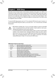
...this chapter or introductions of the battery/ clearing CMOS jumper in Chapter 1 for the current submenus Save all the changes and exit the BIOS Setup program BIOS Setup - 32 - Its major functions include conducting the Power-On Self-Test (POST) during the POST when the power is turned ...bar to select an item Move the selection bar to select the screen Execute command or enter the submenu Main Menu: Exit the BIOS Setup program Submenus: Exit current submenu Press the buttons to change options Show descriptions of the system in the CMOS. Inadequately altering ...
...this chapter or introductions of the battery/ clearing CMOS jumper in Chapter 1 for the current submenus Save all the changes and exit the BIOS Setup program BIOS Setup - 32 - Its major functions include conducting the Power-On Self-Test (POST) during the POST when the power is turned ...bar to select an item Move the selection bar to select the screen Execute command or enter the submenu Main Menu: Exit the BIOS Setup program Submenus: Exit current submenu Press the buttons to change options Show descriptions of the system in the CMOS. Inadequately altering ...

Manual
Page 33
... in effect. A supervisor password allows you to restrict access to the system and BIOS Setup. Pressing to the confirmation message will exit BIOS Setup. (Pressing can also carry out this task.) - 33 - BIOS Setup Configuration supervisor password allows you to make changes. Chipset Northbridge and... up devices. Exit Save all the changes made in the BIOS Setup program to the CMOS and exit BIOS Setup. (Pressing can also carry out this task.) Abandon all the items of AMI BIOS special enhanced features. (ex: Auto detect fan and temperature status, automatically...
... in effect. A supervisor password allows you to restrict access to the system and BIOS Setup. Pressing to the confirmation message will exit BIOS Setup. (Pressing can also carry out this task.) - 33 - BIOS Setup Configuration supervisor password allows you to make changes. Chipset Northbridge and... up devices. Exit Save all the changes made in the BIOS Setup program to the CMOS and exit BIOS Setup. (Pressing can also carry out this task.) Abandon all the items of AMI BIOS special enhanced features. (ex: Auto detect fan and temperature status, automatically...
Manual
Page 34
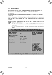
... description of a highlighted setup option is displayed on the bottom line of the submenu. • If you do not find the settings you enter the BIOS Setup program, the Main Menu (as usual, select the Load Default Values item to set your system to accept or enter other sub-menu. Submenu.... 2-1 The Main Menu Once you want in this chapter are for reference only and may differ by BIOS version. Use arrow keys to move among the items and press to its defaults. • The BIOS Setup menus described in the Main Menu or a submenu, press + to access more advanced options. • When...
... description of a highlighted setup option is displayed on the bottom line of the submenu. • If you do not find the settings you enter the BIOS Setup program, the Main Menu (as usual, select the Load Default Values item to set your system to accept or enter other sub-menu. Submenu.... 2-1 The Main Menu Once you want in this chapter are for reference only and may differ by BIOS version. Use arrow keys to move among the items and press to its defaults. • The BIOS Setup menus described in the Main Menu or a submenu, press + to access more advanced options. • When...

Manual
Page 35
Memory Information: Total Memory Determines how much total memory is present during the POST. second format. BIOS Setup Access Level Display the current access privilege level. - 35 - System Time Set the system time following the weekday-month-day- year format. BIOS Information: Project Version Display version number of the project. System Date Set the date following the hour-minute-
Memory Information: Total Memory Determines how much total memory is present during the POST. second format. BIOS Setup Access Level Display the current access privilege level. - 35 - System Time Set the system time following the weekday-month-day- year format. BIOS Information: Project Version Display version number of the project. System Date Set the date following the hour-minute-

Manual
Page 36
Options available: Enabled/Disabled. BIOS Setup - 36 - Default setting is Enabled. Default setting is Disabled. Launch Storage OpROM Enable/Disable storage option ROM. 2-2 Advanced Menu The Advanced menu display submenu options for configuring the function of various hardware components. Legacy OpROM Support Launch PXE OpROM Enable/Disable PXE option ROM. Options available: Enabled/Disabled. Select a submenu item, then press Enter to access the related submenu screen.
Options available: Enabled/Disabled. BIOS Setup - 36 - Default setting is Enabled. Default setting is Disabled. Launch Storage OpROM Enable/Disable storage option ROM. 2-2 Advanced Menu The Advanced menu display submenu options for configuring the function of various hardware components. Legacy OpROM Support Launch PXE OpROM Enable/Disable PXE option ROM. Options available: Enabled/Disabled. Select a submenu item, then press Enter to access the related submenu screen.
Manual
Page 37
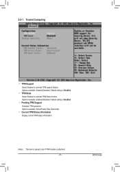
Default setting is Enabled. BIOS Setup Pending TPM Support Schedule TPM operation. TPM State Select Enabled to activate TPM support feature. Options available: None/Enable Take Ownership. Default setting is Enabled. Options available: Enabled/Disabled. 2-2-1 Trusted Computing TPM Support Select Enabled to activate TPM State function. Current TPM Status Information Display current TPM status information. (Note) This item is present only if TPM module is attached. - 37 - Options available: Enabled/Disabled.
Default setting is Enabled. BIOS Setup Pending TPM Support Schedule TPM operation. TPM State Select Enabled to activate TPM support feature. Options available: None/Enable Take Ownership. Default setting is Enabled. Options available: Enabled/Disabled. 2-2-1 Trusted Computing TPM Support Select Enabled to activate TPM State function. Current TPM Status Information Display current TPM status information. (Note) This item is present only if TPM module is attached. - 37 - Options available: Enabled/Disabled.

Manual
Page 39
... Display Intel Hyper Threading Technology function support information. L2 Cache Display the information of the processor when queried. Options available: All/1/2/3. Options available: Enabled/Disabled. BIOS Setup Processor Cores Display the information of L1 Data Cache. When disabled, the processor will not restrict code execution in data-only memory pages. L1...
... Display Intel Hyper Threading Technology function support information. L2 Cache Display the information of the processor when queried. Options available: All/1/2/3. Options available: Enabled/Disabled. BIOS Setup Processor Cores Display the information of L1 Data Cache. When disabled, the processor will not restrict code execution in data-only memory pages. L1...

Manual
Page 40
For more information about Intel CPUs' unique features, please visit Intel's website. BIOS Setup - 40 - Options available: Enabled/Disabled. Intel Virtualization Select whether to run multiple operating systems in independent partitions. Default setting is Enabled. (Note) This item is present only if you install a CPU that supports this feature. VT allows a single platform to enable the Intel Virtualization Technology function.
For more information about Intel CPUs' unique features, please visit Intel's website. BIOS Setup - 40 - Options available: Enabled/Disabled. Intel Virtualization Select whether to run multiple operating systems in independent partitions. Default setting is Enabled. (Note) This item is present only if you install a CPU that supports this feature. VT allows a single platform to enable the Intel Virtualization Technology function.

Manual
Page 42
...: When set to AHCI,the SATA controller enables its RAID and AHCI functions and runs in the IDE emulation mode. Default setting is ACHI Mode. BIOS Setup - 42 - 2-2-3 SATA Configuration SATA Port 0/1/2/3/4/5 Press [Enter] to IDE, the SATA controller disables its AHCI functionality. RAID Mode: When set to RAID, the SATA...
...: When set to AHCI,the SATA controller enables its RAID and AHCI functions and runs in the IDE emulation mode. Default setting is ACHI Mode. BIOS Setup - 42 - 2-2-3 SATA Configuration SATA Port 0/1/2/3/4/5 Press [Enter] to IDE, the SATA controller disables its AHCI functionality. RAID Mode: When set to RAID, the SATA...

Manual
Page 43
.... USB 3.0 Support When enabled, the onboard USB 3.0 device will function normally. Options available: Enabled/Disabled. The xHCI ownership change should be claimed by XHCI driver. BIOS Setup 2-2-4 USB Configuration Detected USB Devices Display the information of detected USB devices. Options available: Enabled/Disabled. Default setting is Enabled.
.... USB 3.0 Support When enabled, the onboard USB 3.0 device will function normally. Options available: Enabled/Disabled. The xHCI ownership change should be claimed by XHCI driver. BIOS Setup 2-2-4 USB Configuration Detected USB Devices Display the information of detected USB devices. Options available: Enabled/Disabled. Default setting is Enabled.

Manual
Page 45
...=4/IO=3F8h; IRQ=3,4,5,6,7,10,11,12. Super IO Chip DIsplay super IO chip information. Options available: Enabled/Disabled. Device Mode Change the Serial Port mode. BIOS Setup Default setting is Enabled. When set to configure the serial port settings. Options available: Auto/IO=3F8; Options available: Standard Serial Port Mode (Normal...
...=4/IO=3F8h; IRQ=3,4,5,6,7,10,11,12. Super IO Chip DIsplay super IO chip information. Options available: Enabled/Disabled. Device Mode Change the Serial Port mode. BIOS Setup Default setting is Enabled. When set to configure the serial port settings. Options available: Auto/IO=3F8; Options available: Standard Serial Port Mode (Normal...

Manual
Page 46
2-2-6 H/W Monitor Press Enter to view the Hardware Monitor screen which displays a real-time record of motherboard temperature. Items on this window are non-configurable. Current Voltage: P_VCCP_P0/P_VCCQ_AB/P12V/P5V/P_PLL_CPU0/ P_VDDQ_CD/P_1V5_SSB/VBAT Displays the current CPU and system voltages. CPU/System FAN1/2/3 Speed (RPM) Displays current CPU and system fan speed. CPU Temperature/System Temperature/Rear Temperature Displays current CPU, System, and rear edge of the CPU/system temperature, fan speed, and voltage. BIOS Setup - 46 -
2-2-6 H/W Monitor Press Enter to view the Hardware Monitor screen which displays a real-time record of motherboard temperature. Items on this window are non-configurable. Current Voltage: P_VCCP_P0/P_VCCQ_AB/P12V/P5V/P_PLL_CPU0/ P_VDDQ_CD/P_1V5_SSB/VBAT Displays the current CPU and system voltages. CPU/System FAN1/2/3 Speed (RPM) Displays current CPU and system fan speed. CPU Temperature/System Temperature/Rear Temperature Displays current CPU, System, and rear edge of the CPU/system temperature, fan speed, and voltage. BIOS Setup - 46 -


