Manual
Page 3
... GA-6PXSV1 Motherboard Layout 5 Chapter 1 Hardware Installation 8 1-1 Installation Precautions 8 1-2 Product Specifications 9 1-3 Installing the CPU and CPU Cooler 11 1-3-1 Installing the CPU...11 1-3-2 Installing the CPU Cooler 13 1-4 Installing the Memory 14 1-4-1 Four Channel Memory Configuration 14 1-4-2 Installing a Memory 15 1-4-3 DIMM Population Table 15 1-5 Back Panel Connectors 16 1-6 Internal Connectors 18 Chapter 2 BIOS Setup 32 2-1 The Main Menu 34 2-2 Advanced Menu 36 2-2-1 Trusted Computing 37 2-2-2 CPU Configuration 38 2-2-2-1 CPU Power Management Configuration...
... GA-6PXSV1 Motherboard Layout 5 Chapter 1 Hardware Installation 8 1-1 Installation Precautions 8 1-2 Product Specifications 9 1-3 Installing the CPU and CPU Cooler 11 1-3-1 Installing the CPU...11 1-3-2 Installing the CPU Cooler 13 1-4 Installing the Memory 14 1-4-1 Four Channel Memory Configuration 14 1-4-2 Installing a Memory 15 1-4-3 DIMM Population Table 15 1-5 Back Panel Connectors 16 1-6 Internal Connectors 18 Chapter 2 BIOS Setup 32 2-1 The Main Menu 34 2-2 Advanced Menu 36 2-2-1 Trusted Computing 37 2-2-2 CPU Configuration 38 2-2-2-1 CPU Power Management Configuration...
Manual
Page 4
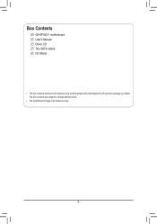
The box contents are for reference only. - 4 - Box Contents GA-6PXSV1 motherboard User's Manual Driver CD Two SATA cables I/O Shield • The box contents above are subject to change without notice. • The motherboard image is for reference only and the actual items shall depend on the product package you obtain.
The box contents are for reference only. - 4 - Box Contents GA-6PXSV1 motherboard User's Manual Driver CD Two SATA cables I/O Shield • The box contents above are subject to change without notice. • The motherboard image is for reference only and the actual items shall depend on the product package you obtain.

Manual
Page 6
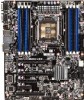
... slot (channel D-0 ) DIMM slot (channel C-1 ) DIMM slot (channel C-0 ) 24 pin power connector System fan cable connectors SATA 6Gb/s connectors SATA 3Gb/s connectors Battery socket Power LED header Clear CMOS jumper Front panel connector System fan cable connectors Mini SAS connector Front USB 3.0 connector Front USB 3.0 connector PCI slot (32bit/33MHz) TPM module IEEE 1394 connector BIOS write protect jumper ME recovery jumper BIOS recovery jumper Clear password jumper Front Audio connector SPDIF header PCI-E slot 4 (x4 slot) PCI-E slot 3 (x8 slot) PCI-E slot 2 (x16 slot/x8 signal) PCI-E slot...
... slot (channel D-0 ) DIMM slot (channel C-1 ) DIMM slot (channel C-0 ) 24 pin power connector System fan cable connectors SATA 6Gb/s connectors SATA 3Gb/s connectors Battery socket Power LED header Clear CMOS jumper Front panel connector System fan cable connectors Mini SAS connector Front USB 3.0 connector Front USB 3.0 connector PCI slot (32bit/33MHz) TPM module IEEE 1394 connector BIOS write protect jumper ME recovery jumper BIOS recovery jumper Clear password jumper Front Audio connector SPDIF header PCI-E slot 4 (x4 slot) PCI-E slot 3 (x8 slot) PCI-E slot 2 (x16 slot/x8 signal) PCI-E slot...
Manual
Page 8
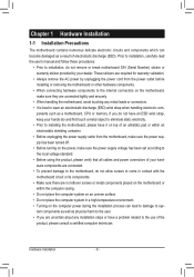
... installation, do not remove or break motherboard S/N (Serial Number) sticker or warranty sticker provided by unplugging the power cord from the motherboard, make sure the power supply has been turned off. • Before turning on the motherboard, make sure the power supply voltage has been set according to the local voltage standard. • Before using the product, please verify that all cables and power connectors of your hardware components are connected...
... installation, do not remove or break motherboard S/N (Serial Number) sticker or warranty sticker provided by unplugging the power cord from the motherboard, make sure the power supply has been turned off. • Before turning on the motherboard, make sure the power supply voltage has been set according to the local voltage standard. • Before using the product, please verify that all cables and power connectors of your hardware components are connected...

Manual
Page 11
... enabling Four Channel mode with two or four memory modules, it is recommended that memory of the memory. Four Channel mode cannot be used for the latest supported memory speeds and memory modules.) • Always turn off the computer and unplug the power cord from the power outlet before installing the memory to insert the memory, switch the direction. 1-4-1 Four Channel Memory Configuration This motherboard provides four DDR3 memory sockets and supports Four Channel Technology. Hardware Installation It is installed, the BIOS...
... enabling Four Channel mode with two or four memory modules, it is recommended that memory of the memory. Four Channel mode cannot be used for the latest supported memory speeds and memory modules.) • Always turn off the computer and unplug the power cord from the power outlet before installing the memory to insert the memory, switch the direction. 1-4-1 Four Channel Memory Configuration This motherboard provides four DDR3 memory sockets and supports Four Channel Technology. Hardware Installation It is installed, the BIOS...

Manual
Page 12
... Speaker Out/Blue) The default Surround Speaker Out (Rear Speaker Out) jack. Hardware Installation - 12 - ter/Subwoofer Speaker Out jack. 1-5 Back Panel Connectors Serial Port Connects to MIC In jack. USB 2.0/1.1 Port The USB port supports the USB 2.0/1.1 specification. RJ-45 LAN Port The Gigabit Ethernet LAN port provides Internet connection at up to 1 Gbps data rate. The following describes the states of Electrical and Electronics Engineers, which hasfeatures with high speed, high bandwidth and hot plug. Devices...
... Speaker Out/Blue) The default Surround Speaker Out (Rear Speaker Out) jack. Hardware Installation - 12 - ter/Subwoofer Speaker Out jack. 1-5 Back Panel Connectors Serial Port Connects to MIC In jack. USB 2.0/1.1 Port The USB port supports the USB 2.0/1.1 specification. RJ-45 LAN Port The Gigabit Ethernet LAN port provides Internet connection at up to 1 Gbps data rate. The following describes the states of Electrical and Electronics Engineers, which hasfeatures with high speed, high bandwidth and hot plug. Devices...

Manual
Page 14
... a system fan be installed inside the chassis. The motherboard supports CPU fan speed control, which requires the use of a CPU fan with fan speed control design. When connecting a fan cable, be sure to connect it is the ground wire). SYS_FAN1 CPU_FAN1 1 SYS_FAN1 1 CPU_FAN1 SYS_FAN2 SYS_FAN3 SYS_FAN2 Pin No. 1 2 3 4 Definition GND +12V / Speed Control Sense Speed Control SYS_FAN3 • Be sure to connect fan cables to the fan headers to the CPU or the system may hang. • These fan headers are not configuration jumper blocks...
... a system fan be installed inside the chassis. The motherboard supports CPU fan speed control, which requires the use of a CPU fan with fan speed control design. When connecting a fan cable, be sure to connect it is the ground wire). SYS_FAN1 CPU_FAN1 1 SYS_FAN1 1 CPU_FAN1 SYS_FAN2 SYS_FAN3 SYS_FAN2 Pin No. 1 2 3 4 Definition GND +12V / Speed Control Sense Speed Control SYS_FAN3 • Be sure to connect fan cables to the fan headers to the CPU or the system may hang. • These fan headers are not configuration jumper blocks...

Manual
Page 15
...; ŠŠ ŠŠ ŠŠ ŠŠ 2 x SATA 6Gb/s connectors (SATA0/1) 4 x SATA 3Gb/s connectors (SATA2/3/4/5) 1 x SAS 3Gb/s connectors (SAS0_3) 6 x USB 2.0/1.1 ports Up to 4 USB 3.0 ports (4 via the USB brackets connected to the internal USB headers) 1 x 24-pin ATX main power connector 1 x 8-pin ATX 12V power connector 4 x SATA 3Gb/s connectors 2 x SATA 6Gb/s connectors 1 x SAS 3Gb/s connector 1 x CPU fan header 3 x System fan header 1 x front panel header 2 x USB 3.0 headers 1 x TPM header 1 x Front 1394 header 1 x Front audio header 1 x Power LED header - 15 -
...; ŠŠ ŠŠ ŠŠ ŠŠ 2 x SATA 6Gb/s connectors (SATA0/1) 4 x SATA 3Gb/s connectors (SATA2/3/4/5) 1 x SAS 3Gb/s connectors (SAS0_3) 6 x USB 2.0/1.1 ports Up to 4 USB 3.0 ports (4 via the USB brackets connected to the internal USB headers) 1 x 24-pin ATX main power connector 1 x 8-pin ATX 12V power connector 4 x SATA 3Gb/s connectors 2 x SATA 6Gb/s connectors 1 x SAS 3Gb/s connector 1 x CPU fan header 3 x System fan header 1 x front panel header 2 x USB 3.0 headers 1 x TPM header 1 x Front 1394 header 1 x Front audio header 1 x Power LED header - 15 -

Manual
Page 16
... according to your hardware specifications including the CPU, graphics card, memory, hard drive, etc. 1-3-1 Installing the CPU A. Alignment Key Alignment Key Pin One Corner of the CPU. The CPU cannot be inserted if oriented incorrectly. (Or you may occur. • Set the CPU host frequency in accordance with the CPU specifications. age of the CPU may locate the notches on both sides of the CPU and alignment keys on the CPU socket.) • Apply an...
... according to your hardware specifications including the CPU, graphics card, memory, hard drive, etc. 1-3-1 Installing the CPU A. Alignment Key Alignment Key Pin One Corner of the CPU. The CPU cannot be inserted if oriented incorrectly. (Or you may occur. • Set the CPU host frequency in accordance with the CPU specifications. age of the CPU may locate the notches on both sides of the CPU and alignment keys on the CPU socket.) • Apply an...

Manual
Page 17
... your CPU cooler.) Step 1: Apply an even and thin layer of thermal grease on the surface of the CPU cooler to the CPU fan header (CPU_FAN) on the motherboard. Step 4: Finally, attach the power connector of the installed CPU. Please pay more attention when removing the CPU cooler because the thermal grease/tape between the CPU cooler and CPU may damage the CPU. - 17 - Hardware Installation
... your CPU cooler.) Step 1: Apply an even and thin layer of thermal grease on the surface of the CPU cooler to the CPU fan header (CPU_FAN) on the motherboard. Step 4: Finally, attach the power connector of the installed CPU. Please pay more attention when removing the CPU cooler because the thermal grease/tape between the CPU cooler and CPU may damage the CPU. - 17 - Hardware Installation

Manual
Page 18
... the DIMM slot, and push it down. Step 3. Step 2. Note: For dual-channel and four-channel operation, DIMMs must be installed in matched pairs. Hardware Installation 1-4-2 Installing a Memory Before installing a memory module, make sure to turn off the computer and unplug the power cord from the power outlet to prevent damage to install DDR3 DIMMs on this motherboard. Be sure to the memory module. Installation Step: Step...
... the DIMM slot, and push it down. Step 3. Step 2. Note: For dual-channel and four-channel operation, DIMMs must be installed in matched pairs. Hardware Installation 1-4-2 Installing a Memory Before installing a memory module, make sure to turn off the computer and unplug the power cord from the power outlet to prevent damage to install DDR3 DIMMs on this motherboard. Be sure to the memory module. Installation Step: Step...

Manual
Page 29
... to BIOS Setup Exit menu and load factory defaults (select Load Default Values) or manually configure the BIOS settings (refer to factory defaults. date information and BIOS configurations) and reset the CMOS values to Chapter 2, "BIOS Setup," for a few seconds. 1-2 Close: Normal operation (Default setting) 1 2-3 Close: Clear CMOS data 1 • Always turn off your computer, be sure to clear the CMOS values (e.g. To clear the CMOS values, place a jumper cap on the two pins to temporarily short the two pins or use...
... to BIOS Setup Exit menu and load factory defaults (select Load Default Values) or manually configure the BIOS settings (refer to factory defaults. date information and BIOS configurations) and reset the CMOS values to Chapter 2, "BIOS Setup," for a few seconds. 1-2 Close: Normal operation (Default setting) 1 2-3 Close: Clear CMOS data 1 • Always turn off your computer, be sure to clear the CMOS values (e.g. To clear the CMOS values, place a jumper cap on the two pins to temporarily short the two pins or use...
Manual
Page 31
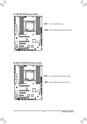
Hardware Installation 23) SSB_ME1 (ME Recovery Jumper) 1 1-2 Close: Enable ME recovery. 1 2-3 Close: Disable ME recovery. (Default setting) 24) BIOS_WP (BIOS Write Protect Jumper) 1 1-2 Close: Normal operation. (Default setting) 1 2-3 Close: Enable BIOS write protect function. - 31 -
Hardware Installation 23) SSB_ME1 (ME Recovery Jumper) 1 1-2 Close: Enable ME recovery. 1 2-3 Close: Disable ME recovery. (Default setting) 24) BIOS_WP (BIOS Write Protect Jumper) 1 1-2 Close: Normal operation. (Default setting) 1 2-3 Close: Enable BIOS write protect function. - 31 -
Manual
Page 32
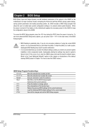
... battery on the motherboard supplies the necessary power to the CMOS to change options Show descriptions of the function keys Restore the previous BIOS settings for the current submenus Load the Optimized BIOS default settings for how to clear the CMOS values.) BIOS Setup Program Function Keys Move the selection bar to select an item Move the selection bar to select the screen Execute command or enter the submenu Main Menu: Exit the BIOS Setup...
... battery on the motherboard supplies the necessary power to the CMOS to change options Show descriptions of the function keys Restore the previous BIOS settings for the current submenus Load the Optimized BIOS default settings for how to clear the CMOS values.) BIOS Setup Program Function Keys Move the selection bar to select an item Move the selection bar to select the screen Execute command or enter the submenu Main Menu: Exit the BIOS Setup...

Manual
Page 36
Legacy OpROM Support Launch PXE OpROM Enable/Disable PXE option ROM. Default setting is Enabled. Default setting is Disabled. BIOS Setup - 36 - Select a submenu item, then press Enter to access the related submenu screen. Options available: Enabled/Disabled. 2-2 Advanced Menu The Advanced menu display submenu options for configuring the function of various hardware components. Options available: Enabled/Disabled. Launch Storage OpROM Enable/Disable storage option ROM.
Legacy OpROM Support Launch PXE OpROM Enable/Disable PXE option ROM. Default setting is Enabled. Default setting is Disabled. BIOS Setup - 36 - Select a submenu item, then press Enter to access the related submenu screen. Options available: Enabled/Disabled. 2-2 Advanced Menu The Advanced menu display submenu options for configuring the function of various hardware components. Options available: Enabled/Disabled. Launch Storage OpROM Enable/Disable storage option ROM.

Manual
Page 42
...setup utility at boot time. Options available: IDE/RAID/ACHI. ACHI Mode: When set to IDE, the SATA controller disables its RAID and AHCI functions and runs in the IDE emulation mode. Default setting is not allowed to AHCI,the SATA controller enables its AHCI functionality. IDE Mode: When set to access RAID setup utility. RAID Mode: When set to view the installed HDD devices. SATA Mode Select the on chip SATA type. BIOS Setup - 42 - Then the RAID function is disabled and cannot be allows access the RAID setup utility at boot time. 2-2-3 SATA Configuration SATA Port...
...setup utility at boot time. Options available: IDE/RAID/ACHI. ACHI Mode: When set to IDE, the SATA controller disables its RAID and AHCI functions and runs in the IDE emulation mode. Default setting is not allowed to AHCI,the SATA controller enables its AHCI functionality. IDE Mode: When set to access RAID setup utility. RAID Mode: When set to view the installed HDD devices. SATA Mode Select the on chip SATA type. BIOS Setup - 42 - Then the RAID function is disabled and cannot be allows access the RAID setup utility at boot time. 2-2-3 SATA Configuration SATA Port...

Manual
Page 43
... setting is Enabled. - 43 - The xHCI ownership change should be claimed by XHCI driver. Default setting is Enabled. Legacy USB Support Enables or disables support for OS without xHCI hand-off support. Options available: Enabled/Disabled. USB 3.0 Support When enabled, the onboard USB 3.0 device will function normally. Default setting is a workround for legacy USB devices. BIOS Setup Options available: Enabled/Disabled. Options available: Enabled/Disabled. XHCI Hand-off This is Enabled. 2-2-4 USB Configuration Detected USB Devices Display the information of detected USB...
... setting is Enabled. - 43 - The xHCI ownership change should be claimed by XHCI driver. Default setting is Enabled. Legacy USB Support Enables or disables support for OS without xHCI hand-off support. Options available: Enabled/Disabled. USB 3.0 Support When enabled, the onboard USB 3.0 device will function normally. Default setting is a workround for legacy USB devices. BIOS Setup Options available: Enabled/Disabled. Options available: Enabled/Disabled. XHCI Hand-off This is Enabled. 2-2-4 USB Configuration Detected USB Devices Display the information of detected USB...

Manual
Page 52
.../4GB/8GB/16GB/32GB/64GB/128GB. DCA Support Enable/Disable Direct Cache Access Support function. Options available: Enabled/Disabled. Options available: Onboard/Offboard. Default setting is Disabled. Default setting is Offboard. BIOS Setup - 52 - Target VGA Displays the information of Target VGA. Options available: Enabled/Disabled. Options available: Auto/Manual. Default setting is Auto. IOH Resource Selection Type When this item is Disabled. Default setting is Enabled. When this item is set to Auto, PCI resources allocation across multiple IOHs based rations...
.../4GB/8GB/16GB/32GB/64GB/128GB. DCA Support Enable/Disable Direct Cache Access Support function. Options available: Enabled/Disabled. Options available: Onboard/Offboard. Default setting is Disabled. Default setting is Offboard. BIOS Setup - 52 - Target VGA Displays the information of Target VGA. Options available: Enabled/Disabled. Options available: Auto/Manual. Default setting is Auto. IOH Resource Selection Type When this item is Disabled. Default setting is Enabled. When this item is set to Auto, PCI resources allocation across multiple IOHs based rations...

Manual
Page 56
Options available: Enabled/Disabled. Default setting is Enabled. Default setting is Enabled. Azalia internal HDMI Enable/Disable onboard audio HDMI controller. Options available: Enabled/Disabled. Audio Configuration Azalia HD Audio Enable/Disable onboard audio controller. BIOS Setup - 56 - Options available: Enabled/Disabled. Onboard SATA RAID oprom Enable/Disable onboard SATA RAID option ROM. Default setting is Enabled.
Options available: Enabled/Disabled. Default setting is Enabled. Default setting is Enabled. Azalia internal HDMI Enable/Disable onboard audio HDMI controller. Options available: Enabled/Disabled. Audio Configuration Azalia HD Audio Enable/Disable onboard audio controller. BIOS Setup - 56 - Options available: Enabled/Disabled. Onboard SATA RAID oprom Enable/Disable onboard SATA RAID option ROM. Default setting is Enabled.
Manual
Page 59
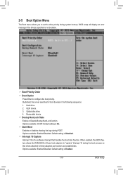
BIOS setup will display an error message if the drive(s) specified is Enabled. - 59 - UEFI device. 3. Options available: On/Off. Quiet Boot Enables or disables showing the logo during the boot process so that handles the boot disk function. Removable device. Bootup NumLock State Enable or Disable Bootup NumLock function. When enabled, this BIOS feature allows the ROM BIOS of those host adaptors to these adaptors can function as bootable disks. Default setting is not bootable. Hard drive. 2. Default setting is...
BIOS setup will display an error message if the drive(s) specified is Enabled. - 59 - UEFI device. 3. Options available: On/Off. Quiet Boot Enables or disables showing the logo during the boot process so that handles the boot disk function. Removable device. Bootup NumLock State Enable or Disable Bootup NumLock function. When enabled, this BIOS feature allows the ROM BIOS of those host adaptors to these adaptors can function as bootable disks. Default setting is not bootable. Hard drive. 2. Default setting is...


