Manual
Page 4
... Layout 7 G1.Sniper Motherboard Block Diagram 8 Chapter 1 Hardware Installation 9 1-1 Installation Precautions 9 1-2 Product Specifications 10 1-3 Installing the CPU and CPU Cooler 13 1-3-1 Installing the CPU 13 1-3-2 Installing the CPU Cooler 15 1-4 Installing the Memory 16 1-4-1 Dual/3 Channel Memory Configuration 16 1-4-2 Installing a Memory 17 1-5 Installing an Expansion Card 18 1-6 Setup of ATI CrossFireX™/NVIDIA SLI Configuration 19 1-7 Back Panel Connectors 20 1-8 Onboard LEDs and Switches 22 1-9 Internal Connectors 25 Chapter 2 BIOS Setup 33 2-1 Startup Screen...
... Layout 7 G1.Sniper Motherboard Block Diagram 8 Chapter 1 Hardware Installation 9 1-1 Installation Precautions 9 1-2 Product Specifications 10 1-3 Installing the CPU and CPU Cooler 13 1-3-1 Installing the CPU 13 1-3-2 Installing the CPU Cooler 15 1-4 Installing the Memory 16 1-4-1 Dual/3 Channel Memory Configuration 16 1-4-2 Installing a Memory 17 1-5 Installing an Expansion Card 18 1-6 Setup of ATI CrossFireX™/NVIDIA SLI Configuration 19 1-7 Back Panel Connectors 20 1-8 Onboard LEDs and Switches 22 1-9 Internal Connectors 25 Chapter 2 BIOS Setup 33 2-1 Startup Screen...
Manual
Page 19
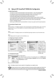
... bridge connector(s) - The 2-Way SLI and 2-Way CrossFireX technologies currently support Windows 7, Vista, and XP operating systems - Current GPUs that came with two/three PCI Express x16 slots and correct driver - Step 3: Plug the display cable into the graphics card on your graphics cards. System Requirements - A CrossFireX/SLI-supported motherboard with your graphics cards for more information about enabling CrossFireX/SLI technology. - 19 - CrossFireX/SLI-supported graphics cards of your graphics cards for the power requirement) B. Configuring the Graphics Card Driver...
... bridge connector(s) - The 2-Way SLI and 2-Way CrossFireX technologies currently support Windows 7, Vista, and XP operating systems - Current GPUs that came with two/three PCI Express x16 slots and correct driver - Step 3: Plug the display cable into the graphics card on your graphics cards. System Requirements - A CrossFireX/SLI-supported motherboard with your graphics cards for more information about enabling CrossFireX/SLI technology. - 19 - CrossFireX/SLI-supported graphics cards of your graphics cards for the power requirement) B. Configuring the Graphics Card Driver...
Manual
Page 20
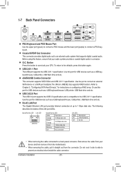
...Installation - 20 - 1-7 Back Panel Connectors O.C. Button Press this button again. Refer to Chapter 5, "Configuring SATA Hard Drive(s)," for USB devices such as a USB keyboard/mouse, USB printer, USB flash drive and etc. Do not rock it straight out from the motherboard. • When removing the cable, pull it side to side to overclock your CPU. O.C. To return to the defaults, press this button to prevent an electrical short inside the cable connector. USB 2.0/1.1 Port The USB port supports the USB 2.0/1.1 specification. Speed/Activity LED Link LED LAN Port Speed/Activity LED...
...Installation - 20 - 1-7 Back Panel Connectors O.C. Button Press this button again. Refer to Chapter 5, "Configuring SATA Hard Drive(s)," for USB devices such as a USB keyboard/mouse, USB printer, USB flash drive and etc. Do not rock it straight out from the motherboard. • When removing the cable, pull it side to side to overclock your CPU. O.C. To return to the defaults, press this button to prevent an electrical short inside the cable connector. USB 2.0/1.1 Port The USB port supports the USB 2.0/1.1 specification. Speed/Activity LED Link LED LAN Port Speed/Activity LED...
Manual
Page 32
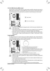
... clear the CMOS values, place a jumper cap on your computer, be sure to replace the battery by removing the battery: 1. Failure to do so may cause damage to the motherboard. • After system restart, go to BIOS Setup to load factory defaults (select Load Optimized Defaults) or manually configure the BIOS settings (refer to Chapter 2, "BIOS Setup," for one . Gently remove the battery from the battery holder and wait for BIOS configurations). 15) BAT (Battery) The battery provides power...
... clear the CMOS values, place a jumper cap on your computer, be sure to replace the battery by removing the battery: 1. Failure to do so may cause damage to the motherboard. • After system restart, go to BIOS Setup to load factory defaults (select Load Optimized Defaults) or manually configure the BIOS settings (refer to Chapter 2, "BIOS Setup," for one . Gently remove the battery from the battery holder and wait for BIOS configurations). 15) BAT (Battery) The battery provides power...
Manual
Page 34
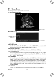
...setting in Boot Menu. Motherboard Model BIOS Version G1.Sniper F1f . . . . : BIOS Setup : XpressRecovery2 : Boot Menu : Qflash 01/19/2011-X58-ICH10-7A89QG0RC-00 Function Keys Function Keys: : POST SCREEN Press the key to show the BIOS POST screen at system startup, refer to access the Q-Flash utility directly without entering BIOS Setup. In Boot Menu, use the up hard drive data using the driver disk, the key can access Boot Menu again to change the first boot device setting as needed. : Q-FLASH Press the key to the instructions on the Full Screen LOGO Show item on BIOS Setup...
...setting in Boot Menu. Motherboard Model BIOS Version G1.Sniper F1f . . . . : BIOS Setup : XpressRecovery2 : Boot Menu : Qflash 01/19/2011-X58-ICH10-7A89QG0RC-00 Function Keys Function Keys: : POST SCREEN Press the key to show the BIOS POST screen at system startup, refer to access the Q-Flash utility directly without entering BIOS Setup. In Boot Menu, use the up hard drive data using the driver disk, the key can access Boot Menu again to change the first boot device setting as needed. : Q-FLASH Press the key to the instructions on the Full Screen LOGO Show item on BIOS Setup...
Manual
Page 36
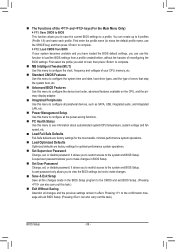
... & Exit Setup Save all the changes made in BIOS Setup. Set User Password Change, set , or disable password. First enter the profile name (to erase the default profile name, use this function to load the BIOS settings from BIOS If your CPU, memory, etc. Standard CMOS Features Use this menu to configure the system time and date, hard drive types, and the type of errors that stop the system boot, etc. Advanced BIOS Features Use this menu to configure the device boot order...
... & Exit Setup Save all the changes made in BIOS Setup. Set User Password Change, set , or disable password. First enter the profile name (to erase the default profile name, use this function to load the BIOS settings from BIOS If your CPU, memory, etc. Standard CMOS Features Use this menu to configure the system time and date, hard drive types, and the type of errors that stop the system boot, etc. Advanced BIOS Features Use this menu to configure the device boot order...
Manual
Page 40
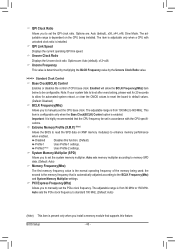
... range is enabled. Options are : Auto (default), x36, x44, x48, Slow Mode. Enabled will allow for automated system reboot, or clear the CMOS values to reset the board to default values. (Default: Disabled) BCLK Frequency(Mhz) Allows you to 600 MHz. Profile2 (Note) Uses Profile 2 settings. PCI Express Frequency(Mhz) Allows you to 150 MHz. The adjustable range is from 100 MHz to manually set the CPU base clock. Important: It is highly recommended...
... range is enabled. Options are : Auto (default), x36, x44, x48, Slow Mode. Enabled will allow for automated system reboot, or clear the CMOS values to reset the board to default values. (Default: Disabled) BCLK Frequency(Mhz) Allows you to 600 MHz. Profile2 (Note) Uses Profile 2 settings. PCI Express Frequency(Mhz) Allows you to 150 MHz. The adjustable range is from 100 MHz to manually set the CPU base clock. Important: It is highly recommended...
Manual
Page 46
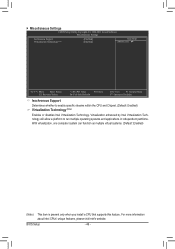
...platform to enable specific streams within the CPU and Chipset. (Default: Enabled) Virtualization Technology (Note) Enables or disables Intel Virtualization Technology. With virtualization, one computer system can function as multiple virtual systems. (Default: Enabled) (Note) This item is present only when you install a CPU that supports this feature. For more information about Intel CPUs' unique features, please visit Intel's website. BIOS Setup - 46 - Miscellaneous Settings CMOS Setup Utility-Copyright (C) 1984-2011 Award Software Miscellaneous Settings Isochronous Support...
...platform to enable specific streams within the CPU and Chipset. (Default: Enabled) Virtualization Technology (Note) Enables or disables Intel Virtualization Technology. With virtualization, one computer system can function as multiple virtual systems. (Default: Enabled) (Note) This item is present only when you install a CPU that supports this feature. For more information about Intel CPUs' unique features, please visit Intel's website. BIOS Setup - 46 - Miscellaneous Settings CMOS Setup Utility-Copyright (C) 1984-2011 Award Software Miscellaneous Settings Isochronous Support...
Manual
Page 49
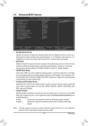
...Options are: Hard Disk, CDROM, USB-FDD, USB-ZIP, USB-CDROM, USBHDD, Legacy LAN, Disabled. BIOS Setup Auto lets the BIOS automatically configure this setting depending on the list. Password Check Specifies whether a password is required for booting the system and for daily use. 2-5 Advanced BIOS Features CMOS Setup Utility-Copyright (C) 1984-2011 Award Software Advanced BIOS Features } Hard Disk Boot Priority Quick Boot CD/DVD Boot Option First Boot Device Second Boot Device Third Boot Device Password Check HDD S.M.A.R.T. Use the up or down arrow key...
...Options are: Hard Disk, CDROM, USB-FDD, USB-ZIP, USB-CDROM, USBHDD, Legacy LAN, Disabled. BIOS Setup Auto lets the BIOS automatically configure this setting depending on the list. Password Check Specifies whether a password is required for booting the system and for daily use. 2-5 Advanced BIOS Features CMOS Setup Utility-Copyright (C) 1984-2011 Award Software Advanced BIOS Features } Hard Disk Boot Priority Quick Boot CD/DVD Boot Option First Boot Device Second Boot Device Third Boot Device Password Check HDD S.M.A.R.T. Use the up or down arrow key...

Manual
Page 50
... attacks when working with its supporting software and system. (Default: Enabled) Delay For HDD (Secs) Allows you to determine whether to Disabled for legacy operating system such as Windows NT4.0. (Default: Disabled) No-Execute Memory Protect (Note) Enables or disables Intel Execute Disable Bit function. If the system BIOS is installed. (Default: Disabled) Limit CPUID Max. Capability Enables or disables the S.M.A.R.T. (Self Monitoring and Reporting Technology) capability of the monitor display from 0 to 15 seconds. (Default: 0) Full Screen LOGO...
... attacks when working with its supporting software and system. (Default: Enabled) Delay For HDD (Secs) Allows you to determine whether to Disabled for legacy operating system such as Windows NT4.0. (Default: Disabled) No-Execute Memory Protect (Note) Enables or disables Intel Execute Disable Bit function. If the system BIOS is installed. (Default: Disabled) Limit CPUID Max. Capability Enables or disables the S.M.A.R.T. (Self Monitoring and Reporting Technology) capability of the monitor display from 0 to 15 seconds. (Default: 0) Full Screen LOGO...

Manual
Page 51
... set to RAID(XHD) au- BIOS Setup 2-6 Integrated Peripherals CMOS Setup Utility-Copyright (C) 1984-2011 Award Software Integrated Peripherals eXtreme Hard Drive (XHD) ICH SATA Control Mode SATA Port0-3 Native Mode USB Controllers USB Keyboard Function USB Mouse Function USB Storage Function Onboard Audio Onboard H/W LAN Onboard USB 3.0 Controller eSATA Controller eSATA Ctrl Mode GSATA3 6_7/IDE Controller GSATA3 6_7/IDE Ctrl Mode [Disabled] [IDE] [Disabled] [Enabled] [Enabled] [Disabled] [Enabled] [Enabled] [Enabled] [Enabled] [Enabled] [IDE] [Enabled...
... set to RAID(XHD) au- BIOS Setup 2-6 Integrated Peripherals CMOS Setup Utility-Copyright (C) 1984-2011 Award Software Integrated Peripherals eXtreme Hard Drive (XHD) ICH SATA Control Mode SATA Port0-3 Native Mode USB Controllers USB Keyboard Function USB Mouse Function USB Storage Function Onboard Audio Onboard H/W LAN Onboard USB 3.0 Controller eSATA Controller eSATA Ctrl Mode GSATA3 6_7/IDE Controller GSATA3 6_7/IDE Ctrl Mode [Disabled] [IDE] [Disabled] [Enabled] [Enabled] [Disabled] [Enabled] [Enabled] [Enabled] [Enabled] [Enabled] [IDE] [Enabled...

Manual
Page 52
... configures the SATA controller to AHCI mode. Advanced Host Controller Interface (AHCI) is an interface specification that allows the storage driver to enable advanced Serial ATA features such as Native Command Queuing and hot plug. USB Keyboard Function Allows USB keyboard to be used in MS-DOS. (Default: Enabled) USB Mouse Function Allows USB mouse to be used in MS-DOS. (Default: Disabled) USB Storage Function Determines whether to detect USB storage devices, including USB flash drives and USB hard drives during the POST. (Default: Enabled) Onboard Audio Enables or disables...
... configures the SATA controller to AHCI mode. Advanced Host Controller Interface (AHCI) is an interface specification that allows the storage driver to enable advanced Serial ATA features such as Native Command Queuing and hot plug. USB Keyboard Function Allows USB keyboard to be used in MS-DOS. (Default: Enabled) USB Mouse Function Allows USB mouse to be used in MS-DOS. (Default: Disabled) USB Storage Function Determines whether to detect USB storage devices, including USB flash drives and USB hard drives during the POST. (Default: Enabled) Onboard Audio Enables or disables...
Manual
Page 53
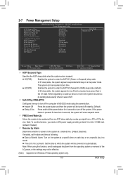
... F6: Fail-Safe Defaults ESC: Exit F1: General Help F7: Optimized Defaults ACPI Suspend Type Specifies the ACPI sleep state when the system enters suspend. Press and hold the power button for less than in a low power mode. 2-7 Power Management Setup CMOS Setup Utility-Copyright (C) 1984-2011 Award Software Power Management Setup ACPI Suspend Type Soft-Off by PWR-BTTN PME Event Wake Up Resume by a wake-up signal from a PCI or PCIe device. In S3 sleep state, the...
... F6: Fail-Safe Defaults ESC: Exit F1: General Help F7: Optimized Defaults ACPI Suspend Type Specifies the ACPI sleep state when the system enters suspend. Press and hold the power button for less than in a low power mode. 2-7 Power Management Setup CMOS Setup Utility-Copyright (C) 1984-2011 Award Software Power Management Setup ACPI Suspend Type Soft-Off by PWR-BTTN PME Event Wake Up Resume by a wake-up signal from a PCI or PCIe device. In S3 sleep state, the...
Manual
Page 69
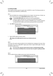
Step 3: When the update process is saved to a hard drive in RAID/AHCI mode or a hard drive attached to an independent SATA controller, use the up or down arrow key to begin the BIOS update. Update BIOS from Drive Save BIOS to the main menu. Q-Flash Utility v2.23 Flash Type/Size MXIC 25L1605/1606 2M Keep0 DfilMe(Is)DfaotuandEnable HDD 1-0 Loa d CMO S Default Enable Update BIOS from Drive Please SparevsesBaInOySketoy Dtoricvoentinue Enter : Run hi:Move ESC:Reset F10:Power Off - 69 - Select the BIOS update file and press...
Step 3: When the update process is saved to a hard drive in RAID/AHCI mode or a hard drive attached to an independent SATA controller, use the up or down arrow key to begin the BIOS update. Update BIOS from Drive Save BIOS to the main menu. Q-Flash Utility v2.23 Flash Type/Size MXIC 25L1605/1606 2M Keep0 DfilMe(Is)DfaotuandEnable HDD 1-0 Loa d CMO S Default Enable Update BIOS from Drive Please SparevsesBaInOySketoy Dtoricvoentinue Enter : Run hi:Move ESC:Reset F10:Power Off - 69 - Select the BIOS update file and press...
Manual
Page 81
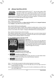
... to the Application Software screen to exit the X.H.D utility. (Note 1) The X.H.D utility only supports the SATA controllers integrated in the array. ) 1. Using GIGABYTE eXtreme Hard Drive (X.H.D) Instructions: (Note 2) Before launching X.H.D, make sure the new drive is greater than the RAID-ready system drive. (To add a new hard drive into the array to load the SATA controller driver first. Before installing the operating system, you 'll not be recognized during the Windows setup process. (For...
... to the Application Software screen to exit the X.H.D utility. (Note 1) The X.H.D utility only supports the SATA controllers integrated in the array. ) 1. Using GIGABYTE eXtreme Hard Drive (X.H.D) Instructions: (Note 2) Before launching X.H.D, make sure the new drive is greater than the RAID-ready system drive. (To add a new hard drive into the array to load the SATA controller driver first. Before installing the operating system, you 'll not be recognized during the Windows setup process. (For...
Manual
Page 105
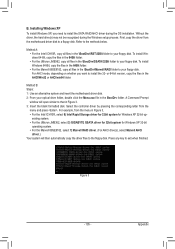
... for Windows XP 32-bit op- Press any key to the methods below. Method B: Steps: 1: Use an alternative system and insert the motherboard driver disk. 2: From your floppy disk. Select the controller driver by pressing the corresponding letter from the motherboard driver disk to a floppy disk. Method A: • For the Intel ICH10R, copy all files in the \BootDrv\Marvell\RAID folder to the floppy disk. To install Windows 64-Bit, copy the files in...
... for Windows XP 32-bit op- Press any key to the methods below. Method B: Steps: 1: Use an alternative system and insert the motherboard driver disk. 2: From your floppy disk. Select the controller driver by pressing the corresponding letter from the motherboard driver disk to a floppy disk. Method A: • For the Intel ICH10R, copy all files in the \BootDrv\Marvell\RAID folder to the floppy disk. To install Windows 64-Bit, copy the files in...
Manual
Page 107
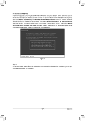
... 91xx SATA RAID Controller 64bit Driver ENTER=Select F3=Exit Figure 6 Step 3: On the next screen, press to configure a SCSI Adapter for 32bit (install first) and press . Windows Setup You have chosen to continue the driver installation. After the driver installation, you are installing the 32-bit version. On the next screen, press to return to the screen in Figure 6. For the Marvell 88SE9182: Insert the floppy disk containing the SATA RAID/AHCI driver and...
... 91xx SATA RAID Controller 64bit Driver ENTER=Select F3=Exit Figure 6 Step 3: On the next screen, press to configure a SCSI Adapter for 32bit (install first) and press . Windows Setup You have chosen to continue the driver installation. After the driver installation, you are installing the 32-bit version. On the next screen, press to return to the screen in Figure 6. For the Marvell 88SE9182: Insert the floppy disk containing the SATA RAID/AHCI driver and...
Manual
Page 115
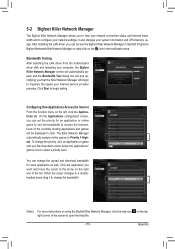
... Help file. - 115 - Bandwidth Testing After installing the LAN driver from the motherboard driver disk and restarting your computer, the Bigfoot Killer Network Manager screen will automatically appear and the Bandwidth Test dialog box will pop up, notifying you that the Killer Network Manager will be displayed in the notification area. On the Applications configuration screen, you can access the Bigfoot Killer Network Manager in Start...
... Help file. - 115 - Bandwidth Testing After installing the LAN driver from the motherboard driver disk and restarting your computer, the Bigfoot Killer Network Manager screen will automatically appear and the Bandwidth Test dialog box will pop up, notifying you that the Killer Network Manager will be displayed in the notification area. On the Applications configuration screen, you can access the Bigfoot Killer Network Manager in Start...
Manual
Page 119
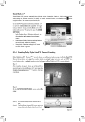
... 2) DTS Connect is supported on how to use each function, click the help file. Users are also available in games. 5-3-4 Enabling Dolby Digital Live/DTS Connect Encoding Dolby Digital Live/DTS Connect (Note 1) converts stereo or multichannel audio sources into Dolby Digital/DTS Connect format. Switch to open the MODE SWITCHER. • Audio Creation Mode: Optimizes settings for 3D audio and EAX effects in the Creative Audio Control Panel...
... 2) DTS Connect is supported on how to use each function, click the help file. Users are also available in games. 5-3-4 Enabling Dolby Digital Live/DTS Connect Encoding Dolby Digital Live/DTS Connect (Note 1) converts stereo or multichannel audio sources into Dolby Digital/DTS Connect format. Switch to open the MODE SWITCHER. • Audio Creation Mode: Optimizes settings for 3D audio and EAX effects in the Creative Audio Control Panel...
Manual
Page 122
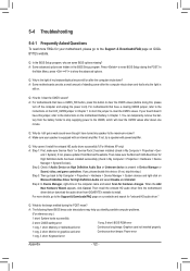
... jumper, refer to the maximum volume? Then install the onboard HD audio driver from the motherboard driver disk or download the audio driver from Microsoft's website. A: The following Award BIOS beep code descriptions may help you identify possible computer problems. (For reference only.) 1 short: System boots successfully 2 short: CMOS setting error 1 long, 9 short: BIOS ROM error 1 long, 1 short: Memory or motherboard error Continuous long beeps: Graphics card not inserted properly 1 long, 2 short: Monitor or graphics card error Continuous short beeps: Power error 1 long...
... jumper, refer to the maximum volume? Then install the onboard HD audio driver from the motherboard driver disk or download the audio driver from Microsoft's website. A: The following Award BIOS beep code descriptions may help you identify possible computer problems. (For reference only.) 1 short: System boots successfully 2 short: CMOS setting error 1 long, 9 short: BIOS ROM error 1 long, 1 short: Memory or motherboard error Continuous long beeps: Graphics card not inserted properly 1 long, 2 short: Monitor or graphics card error Continuous short beeps: Power error 1 long...


