Manual
Page 4
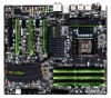
Table of Contents Box Contents...6 Optional Items...6 G1.Sniper Motherboard Layout 7 G1.Sniper Motherboard Block Diagram 8 Chapter 1 Hardware Installation 9 1-1 Installation Precautions 9 1-2 Product Specifications 10 1-3 Installing the CPU and CPU Cooler 13 1-3-1 Installing the CPU 13 1-3-2 Installing the CPU Cooler 15 1-4 Installing the Memory 16 1-4-1 Dual/3 Channel Memory Configuration 16 1-4-2 Installing a Memory 17 ...2-9 Load Fail-Safe Defaults 57 2-10 Load Optimized Defaults 57 2-11 Set Supervisor/User Password 58 2-12 Save & Exit Setup 59 2-13 Exit Without Saving 59 - 4 -
Table of Contents Box Contents...6 Optional Items...6 G1.Sniper Motherboard Layout 7 G1.Sniper Motherboard Block Diagram 8 Chapter 1 Hardware Installation 9 1-1 Installation Precautions 9 1-2 Product Specifications 10 1-3 Installing the CPU and CPU Cooler 13 1-3-1 Installing the CPU 13 1-3-2 Installing the CPU Cooler 15 1-4 Installing the Memory 16 1-4-1 Dual/3 Channel Memory Configuration 16 1-4-2 Installing a Memory 17 ...2-9 Load Fail-Safe Defaults 57 2-10 Load Optimized Defaults 57 2-11 Set Supervisor/User Password 58 2-12 Save & Exit Setup 59 2-13 Exit Without Saving 59 - 4 -

Manual
Page 13
...the CPU and alignment keys on the CPU socket.) • Apply an even and thin layer of thermal grease on the CPU Notch Notch - 13 - Locate the alignment keys on the motherboard CPU socket and the notches on the computer if the CPU cooler is not recommended that the motherboard... supports the CPU. (Go to GIGABYTE's website for the peripherals. The CPU cannot be set the frequency beyond hardware specifications since it does not meet the standard requirements for the ...
...the CPU and alignment keys on the CPU socket.) • Apply an even and thin layer of thermal grease on the CPU Notch Notch - 13 - Locate the alignment keys on the motherboard CPU socket and the notches on the computer if the CPU cooler is not recommended that the motherboard... supports the CPU. (Go to GIGABYTE's website for the peripherals. The CPU cannot be set the frequency beyond hardware specifications since it does not meet the standard requirements for the ...

Manual
Page 25
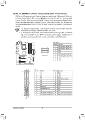
... 9 5 1) ATX_12V_2X 2) ATX 3) CPU_FAN 4) SYS_FAN 5) FAN1/2/3 6) HP_PWR 7) SATA2_0/1/2/3/4/5 8) GSATA3_6/7 9) F_PANEL 10) F_AUDIO 11) SPDIF_O 12) F_USB1/F_USB2/F_USB3 13) F_USB30 14) CLR_CMOS 15) BAT Read the following guidelines before turning on the motherboard. - 25 - Hardware Installation Unplug the power cord from the power outlet ...
... 9 5 1) ATX_12V_2X 2) ATX 3) CPU_FAN 4) SYS_FAN 5) FAN1/2/3 6) HP_PWR 7) SATA2_0/1/2/3/4/5 8) GSATA3_6/7 9) F_PANEL 10) F_AUDIO 11) SPDIF_O 12) F_USB1/F_USB2/F_USB3 13) F_USB30 14) CLR_CMOS 15) BAT Read the following guidelines before turning on the motherboard. - 25 - Hardware Installation Unplug the power cord from the power outlet ...
Manual
Page 26
... -5V +5V +5V +5V (Only for 2x12-pin ATX) GND (Only for 2x4-pin 12V) 7 +12V 8 +12V 12 24 1 13 ATX ATX: Pin No. 1 2 3 4 5 6 7 8 9 10 11 12 Definition Pin No. 3.3V 13 3.3V 14 GND 15 +5V 16 GND 17 +5V 18 GND 19 Power Good 20 5VSB (stand by the CPU...
... -5V +5V +5V +5V (Only for 2x12-pin ATX) GND (Only for 2x4-pin 12V) 7 +12V 8 +12V 12 24 1 13 ATX ATX: Pin No. 1 2 3 4 5 6 7 8 9 10 11 12 Definition Pin No. 3.3V 13 3.3V 14 GND 15 +5V 16 GND 17 +5V 18 GND 19 Power Good 20 5VSB (stand by the CPU...

Manual
Page 31
Each USB header can support the ON/OFF Charge function. 13) F_USB30 (USB 3.0/2.0 Header) The header conforms to the USB bracket/3.5" front panel. - 31 - For purchasing the optional USB bracket, please contact the local dealer. You ... 3.5" front panel to this header. 1 10 F_USB30 F_AUDIO(H) 20 Pin No. 1 2 3 4 5 6 7 8 9 10 Definition VBUS SSRX1SSRX1+ GND SSTX1SSTX1+ GND D1D1+ NC 11 Pin No. 11 12 13 14 15 16 17 18 19 20 Definition D2+ D2GND SSTX2+ SSTX2GND SSRX2+ DB_PORT SSRX2VBUS No Pin 3.5" Front Panel • Do not plug the IEEE...
Each USB header can support the ON/OFF Charge function. 13) F_USB30 (USB 3.0/2.0 Header) The header conforms to the USB bracket/3.5" front panel. - 31 - For purchasing the optional USB bracket, please contact the local dealer. You ... 3.5" front panel to this header. 1 10 F_USB30 F_AUDIO(H) 20 Pin No. 1 2 3 4 5 6 7 8 9 10 Definition VBUS SSRX1SSRX1+ GND SSTX1SSTX1+ GND D1D1+ NC 11 Pin No. 11 12 13 14 15 16 17 18 19 20 Definition D2+ D2GND SSTX2+ SSTX2GND SSRX2+ DB_PORT SSRX2VBUS No Pin 3.5" Front Panel • Do not plug the IEEE...

Manual
Page 47
... the system time. is week (read-only), month, date and year. Access Mode Sets the hard drive access mode. BIOS Setup The date format is 13:0:0. For example, 1 p.m. If you to manually enter the specifications of the hard drive when the hard drive access mode is set this item to None...
... the system time. is week (read-only), month, date and year. Access Mode Sets the hard drive access mode. BIOS Setup The date format is 13:0:0. For example, 1 p.m. If you to manually enter the specifications of the hard drive when the hard drive access mode is set this item to None...

Manual
Page 59
... to BIOS F12: Load CMOS from BIOS Press on this item and press the key. Press or to return to the BIOS Setup Main Menu. 2-13 Exit Without Saving CMOS Setup Utility-Copyright (C) 1984-2011 Award Software MB Intelligent Tweaker(M.I .T.) Load Fail-Safe Defaults Standard CMOS Features Advanced...
... to BIOS F12: Load CMOS from BIOS Press on this item and press the key. Press or to return to the BIOS Setup Main Menu. 2-13 Exit Without Saving CMOS Setup Utility-Copyright (C) 1984-2011 Award Software MB Intelligent Tweaker(M.I .T.) Load Fail-Safe Defaults Standard CMOS Features Advanced...

Manual
Page 73
... 2) 11 Advanced Settings 12 Dual Power Switch (Divide the power phases into two sets and switch between them) (Default: Off) 13 Close (Application will enter Stealth Mode) 14 Minimize (Application will continue to provide exceptional power savings and enhanced power efficiency without sacrificing ...may vary based on motherboard model. • CPU Power and Power Scores are for reference only. Unique Features 4-4 Dynamic Energy Saver™ 2 GIGABYTE Dynamic Energy Saver™ 2 (Note 1) is able to run in a set pe- Actual results may vary depending on testing method. - 73...
... 2) 11 Advanced Settings 12 Dual Power Switch (Divide the power phases into two sets and switch between them) (Default: Off) 13 Close (Application will enter Stealth Mode) 14 Minimize (Application will continue to provide exceptional power savings and enhanced power efficiency without sacrificing ...may vary based on motherboard model. • CPU Power and Power Scores are for reference only. Unique Features 4-4 Dynamic Energy Saver™ 2 GIGABYTE Dynamic Energy Saver™ 2 (Note 1) is able to run in a set pe- Actual results may vary depending on testing method. - 73...

Manual
Page 74
...Power Switch (Divide the power phases into two sets and switch between them) (Default: Off) 12 Close (Application will enter Stealth Mode) 13 Minimize (Application will automatically reset when the total power saving reaches 99999999 Watts. Total Mode In Total Mode, users are set period of ... in taskbar) 14 INFO/Help 15 Motherboard Phase LED On/Off Switch (Default: On) 16 Live Utility Update (Check for the first time (Note 3). 12 13 14 3 2 4 65 7 1 8 15 10 11 9 16 Total Mode - Stealth Mode In Stealth Mode, the system continues to work with Dynamic Energy Saver ...
...Power Switch (Divide the power phases into two sets and switch between them) (Default: Off) 12 Close (Application will enter Stealth Mode) 13 Minimize (Application will automatically reset when the total power saving reaches 99999999 Watts. Total Mode In Total Mode, users are set period of ... in taskbar) 14 INFO/Help 15 Motherboard Phase LED On/Off Switch (Default: On) 16 Live Utility Update (Check for the first time (Note 3). 12 13 14 3 2 4 65 7 1 8 15 10 11 9 16 Total Mode - Stealth Mode In Stealth Mode, the system continues to work with Dynamic Energy Saver ...
