
Manual/User Guide
Page 5
...MAP3147NC/NP, MAP3735NC/NP and MAP3367NC/NP (hereafter, MAP series), 3.5 type fixed disk drives with an embedded SCSI controller. This manual is written for setting device number and operation modes, mounting the disk drive, connecting the cables, and confirming drive operation. OVERVIEW OF MANUAL This ...manual consists of the disk, the address method, and what to install MAP series disk drives. Chapter 3 DATA FORMAT This chapter describes the ...
...MAP3147NC/NP, MAP3735NC/NP and MAP3367NC/NP (hereafter, MAP series), 3.5 type fixed disk drives with an embedded SCSI controller. This manual is written for setting device number and operation modes, mounting the disk drive, connecting the cables, and confirming drive operation. OVERVIEW OF MANUAL This ...manual consists of the disk, the address method, and what to install MAP series disk drives. Chapter 3 DATA FORMAT This chapter describes the ...
Manual/User Guide
Page 7
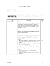
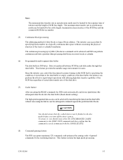
...during operation and remain hot immediately after turning off the power. Hot temperature To prevent injury, do not handle the drive until after the device has 5-1 cooled sufficiently after turning off before connecting or disconnecting cables. 2. This alert signal also indicates that system power is performed. Important Alert Items Important Alert ...except NC model) C141-E166 v Do not change the setting of read sector keeps allowable error byte number, correction is off the power. Do not connect or disconnect cables when power is shipped from the factory.
...during operation and remain hot immediately after turning off the power. Hot temperature To prevent injury, do not handle the drive until after the device has 5-1 cooled sufficiently after turning off before connecting or disconnecting cables. 2. This alert signal also indicates that system power is performed. Important Alert Items Important Alert ...except NC model) C141-E166 v Do not change the setting of read sector keeps allowable error byte number, correction is off the power. Do not connect or disconnect cables when power is shipped from the factory.
Manual/User Guide
Page 8
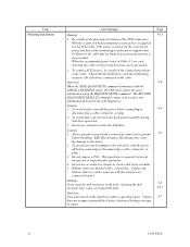
... the device. 2. Check that the SCSI device with a colored line. Caution 1. Do not remove a PCA. Fujitsu 6-7 does not assume responsibility if data is turned on the disk drive before connecting or 6-5 disconnecting a cable, connector, or plug. 2. Task Mounting Installation Alert message Page Damage 5-11 1. Caution 1. ESD (Electrostatics Discharge) may cause an irreparable fault...
... the device. 2. Check that the SCSI device with a colored line. Caution 1. Do not remove a PCA. Fujitsu 6-7 does not assume responsibility if data is turned on the disk drive before connecting or 6-5 disconnecting a cable, connector, or plug. 2. Task Mounting Installation Alert message Page Damage 5-11 1. Caution 1. ESD (Electrostatics Discharge) may cause an irreparable fault...
Manual/User Guide
Page 11
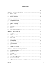
... Addressing 3-9 3.3 Defect Management...3-11 3.3.1 Defect list ...3-11 3.3.2 Alternate block allocation 3-11 CHAPTER 4 INSTALLATION REQUIREMENTS 4-1 4.1 Mounting Requirements ...4-1 4.1.1 External dimensions ...4-1 4.1.2 Mounting ...4-4 4.1.3 Notes on mounting ...4-4 4.2 Power Supply Requirements 4-8 4.3 Connection Requirements 4-11 4.3.1 68 pin connector 16-bit SCSI model (NP model 4-11 C141-E166 ix
... Addressing 3-9 3.3 Defect Management...3-11 3.3.1 Defect list ...3-11 3.3.2 Alternate block allocation 3-11 CHAPTER 4 INSTALLATION REQUIREMENTS 4-1 4.1 Mounting Requirements ...4-1 4.1.1 External dimensions ...4-1 4.1.2 Mounting ...4-4 4.1.3 Notes on mounting ...4-4 4.2 Power Supply Requirements 4-8 4.3 Connection Requirements 4-11 4.3.1 68 pin connector 16-bit SCSI model (NP model 4-11 C141-E166 ix
Manual/User Guide
Page 12
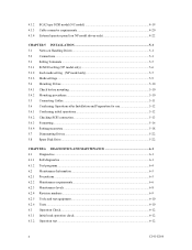
... Cables...5-11 5.6 Confirming Operations after Installation and Preparation for use 5-12 5.6.1 Confirming initial operations 5-12 5.6.2 Checking SCSI connection 5-13 5.6.3 Formatting ...5-16 5.6.4 Setting parameters ...5-18 5.7 Dismounting Drives...5-22 5.8 Spare Disk Drive ...5-22 CHAPTER 6 DIAGNOSTICS AND MAINTENANCE 6-1 6.1 Diagnostics ...6-1 6.1.1 Self-diagnostics ...6-1 6.1.2 Test programs...6-4 6.2 Maintenance Information 6-5 6.2.1 Precautions ...6-5 6.2.2 Maintenance requirements 6-6 6.2.3 Maintenance levels ...6-8 6.2.4 Revision numbers ...6-9 6.2.5 Tools and test equipment...
... Cables...5-11 5.6 Confirming Operations after Installation and Preparation for use 5-12 5.6.1 Confirming initial operations 5-12 5.6.2 Checking SCSI connection 5-13 5.6.3 Formatting ...5-16 5.6.4 Setting parameters ...5-18 5.7 Dismounting Drives...5-22 5.8 Spare Disk Drive ...5-22 CHAPTER 6 DIAGNOSTICS AND MAINTENANCE 6-1 6.1 Diagnostics ...6-1 6.1.1 Self-diagnostics ...6-1 6.1.2 Test programs...6-4 6.2 Maintenance Information 6-5 6.2.1 Precautions ...6-5 6.2.2 Maintenance requirements 6-6 6.2.3 Maintenance levels ...6-8 6.2.4 Revision numbers ...6-9 6.2.5 Tools and test equipment...
Manual/User Guide
Page 16
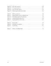
... connector 4-20 External operator panel circuit example 4-22 Figure 5.1 Figure 5.2 Figure 5.3 Figure 5.4 Figure 5.5 SCSI bus connections ...5-4 Setting terminals location (on NP models only 5-5 CN2 setting terminal (on NP models only 5-6 Checking the SCSI connection (A 5-14 Checking the SCSI connection (B 5-15 Figure 6.1 Figure 6.2 Figure 6.3 Revision label ...6-9 Indicating revision numbers 6-10 Test flowchart...6-11 Figure...
... connector 4-20 External operator panel circuit example 4-22 Figure 5.1 Figure 5.2 Figure 5.3 Figure 5.4 Figure 5.5 SCSI bus connections ...5-4 Setting terminals location (on NP models only 5-5 CN2 setting terminal (on NP models only 5-6 Checking the SCSI connection (A 5-14 Checking the SCSI connection (B 5-15 Figure 6.1 Figure 6.2 Figure 6.3 Revision label ...6-9 Indicating revision numbers 6-10 Test flowchart...6-11 Figure...
Manual/User Guide
Page 17
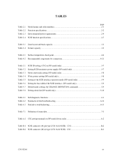
... Table 3.1 Zone layout and track capacity 3-3 Table 3.4 Format capacity ...3-9 Table 4.1 Surface temperature check point 4-6 Table 4.2 Recommended components for connection 4-21 Table 5.1 SCSI ID setting (CN2 on NP model only 5-7 Table 5.2 Setting SCSI terminator power supply (NP model only 5-7 Table... Self-diagnostic functions ...6-1 Table 6.2 System-level field troubleshooting 6-14 Table 6.3 Disk drive troubleshooting ...6-15 Table 7.1 Definition of sense data ...7-3 Table A.1 CN2 setting terminal (on NP model drives only A-2 Table B.1 SCSI connector (68 pin type LVD 16-bit SCSI): CN1...
... Table 3.1 Zone layout and track capacity 3-3 Table 3.4 Format capacity ...3-9 Table 4.1 Surface temperature check point 4-6 Table 4.2 Recommended components for connection 4-21 Table 5.1 SCSI ID setting (CN2 on NP model only 5-7 Table 5.2 Setting SCSI terminator power supply (NP model only 5-7 Table... Self-diagnostic functions ...6-1 Table 6.2 System-level field troubleshooting 6-14 Table 6.3 Disk drive troubleshooting ...6-15 Table 7.1 Definition of sense data ...7-3 Table A.1 CN2 setting terminal (on NP model drives only A-2 Table B.1 SCSI connector (68 pin type LVD 16-bit SCSI): CN1...
Manual/User Guide
Page 20
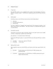
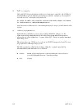
... block addressing regardless of the physical characteristics of the disk drive. For the ultra SCSI model, number of connectable SCSI devices on the same SCSI bus is varied as follows. • 8-bit SCSI: 8 drives max. (option for NP model) • 16-bit SCSI: 16 drives max. (4) High speed data transfer Such a high data...the SCSI bus is 40 MB/s maximum at the synchronous mode. • 16-bit SCSI: The data transfer rate on the SCSI bus can be connected directly to accommodate future expansion of system functions. (3) 8-bit SCSI/16-bit SCSI The IDD has 16-bit data bus width (16-bit SCSI), ...
... block addressing regardless of the physical characteristics of the disk drive. For the ultra SCSI model, number of connectable SCSI devices on the same SCSI bus is varied as follows. • 8-bit SCSI: 8 drives max. (option for NP model) • 16-bit SCSI: 16 drives max. (4) High speed data transfer Such a high data...the SCSI bus is 40 MB/s maximum at the synchronous mode. • 16-bit SCSI: The data transfer rate on the SCSI bus can be connected directly to accommodate future expansion of system functions. (3) 8-bit SCSI/16-bit SCSI The IDD has 16-bit data bus width (16-bit SCSI), ...
Manual/User Guide
Page 21
...feature realizes the high speed processing. This feature provides the suitable usage environment for users. To ensure it, you turn off the drive's power. The maximum data transfer rate in synchronous mode may be achieved by transferring the data from the data buffer without concerning the... in asynchronous mode may be achieved, and IDD can be limited by the cable length, transmission characteristics of the SCSI bus and the connected SCSI device number. (5) Continuous block processing The addressing method of data blocks is 8M bytes. C141-E166 1-3 The high speed sequential...
...feature realizes the high speed processing. This feature provides the suitable usage environment for users. To ensure it, you turn off the drive's power. The maximum data transfer rate in synchronous mode may be achieved by transferring the data from the data buffer without concerning the... in asynchronous mode may be achieved, and IDD can be limited by the cable length, transmission characteristics of the SCSI bus and the connected SCSI device number. (5) Continuous block processing The addressing method of data blocks is 8M bytes. C141-E166 1-3 The high speed sequential...
Manual/User Guide
Page 27
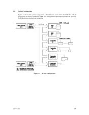
SCSI bus Figure 1.4 System configuration C141-E166 1-9 1.3 System Configuration Figure 1.4 shows the system configuration. The IDDs perform input/output operation as specified by SCSI devices which operate as target. The IDDs are connected to the SCSI bus of host systems and are always operated as initiator.
SCSI bus Figure 1.4 System configuration C141-E166 1-9 1.3 System Configuration Figure 1.4 shows the system configuration. The IDDs perform input/output operation as specified by SCSI devices which operate as target. The IDDs are connected to the SCSI bus of host systems and are always operated as initiator.
Manual/User Guide
Page 28
...up to 16 SCSI devices operating as an initiator or a target can be connected to 15 (switch selectable) 0 (fixed) 1-10 C141-E166 A unique address (LUN: logical unit number) is a single logical unit, the selectable number of disk drive is assigned for the 16-bit SCSI in any combination. The IDD is ...constructed so that operates as multi-host system on the bus has its own unique address (SCSI ID:#n in unit called as initiator or connected through the SCSI bus. For input...
...up to 16 SCSI devices operating as an initiator or a target can be connected to 15 (switch selectable) 0 (fixed) 1-10 C141-E166 A unique address (LUN: logical unit number) is a single logical unit, the selectable number of disk drive is assigned for the 16-bit SCSI in any combination. The IDD is ...constructed so that operates as multi-host system on the bus has its own unique address (SCSI ID:#n in unit called as initiator or connected through the SCSI bus. For input...
Manual/User Guide
Page 31
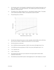
... command. (*5) This value indicates at ready mode. (*6) Up to 4 SCSI devices having capacitance of 25pF or less can use cable length of up to 1.5 m. (*8) 1 on 1 connection case. (*9) 1 host, 15 devices case. (*10) The maximum data transfer rate may be changed by transmission characteristics. (*11) The terminator power pin (SCSI connector) which...
... command. (*5) This value indicates at ready mode. (*6) Up to 4 SCSI devices having capacitance of 25pF or less can use cable length of up to 1.5 m. (*8) 1 on 1 connection case. (*9) 1 host, 15 devices case. (*10) The maximum data transfer rate may be changed by transmission characteristics. (*11) The terminator power pin (SCSI connector) which...
Manual/User Guide
Page 53
C141-E166 4-1 CHAPTER 4 INSTALLATION REQUIREMENTS 4.1 Mounting Requirements 4.2 Power Supply Requirements 4.3 Connection Requirements This chapter describes the environmental, mounting, power supply, and connection requirements. 4.1 Mounting Requirements 4.1.1 External dimensions Figures 4.1 and 4.2 show the external dimensions of the IDD and the locations of the holes for the IDD mounting screws. Note: Dimensions are in mm.
C141-E166 4-1 CHAPTER 4 INSTALLATION REQUIREMENTS 4.1 Mounting Requirements 4.2 Power Supply Requirements 4.3 Connection Requirements This chapter describes the environmental, mounting, power supply, and connection requirements. 4.1 Mounting Requirements 4.1.1 External dimensions Figures 4.1 and 4.2 show the external dimensions of the IDD and the locations of the holes for the IDD mounting screws. Note: Dimensions are in mm.
Manual/User Guide
Page 59
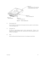
... equipment. (8) Others Seals on NP model only) • External operator panel connector [Surface P] • Cable connection [Surface R] • Hole for mounting screw [Surface Q] • Hole for mounting screw Figure 4.7 Service clearance area (6) External magnetic field The drive should not be installed near the ferromagnetic body like a speaker to achieve a high speed seek...
... equipment. (8) Others Seals on NP model only) • External operator panel connector [Surface P] • Cable connection [Surface R] • Hole for mounting screw [Surface Q] • Hole for mounting screw Figure 4.7 Service clearance area (6) External magnetic field The drive should not be installed near the ferromagnetic body like a speaker to achieve a high speed seek...
Manual/User Guide
Page 63
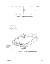
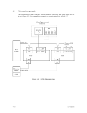
Figure 4.12 AC noise filter (recommended) 4.3 Connection Requirements 4.3.1 68 pin connector 16-bit SCSI model (NP model) (1) Connectors Figures 4.13 show the locations of connectors and terminals on the 68 pin connector type 16-bit SCSI (MP) model. • Power supply connector • SCSI connector • External operator panel connector External operator panel connector (CN2) Power supply connector (CN1) External operator panel connector (CN1) SCSI connector (CN1) Figure 4.13 NP connectors and terminals location C141-E166 4-11
Figure 4.12 AC noise filter (recommended) 4.3 Connection Requirements 4.3.1 68 pin connector 16-bit SCSI model (NP model) (1) Connectors Figures 4.13 show the locations of connectors and terminals on the 68 pin connector type 16-bit SCSI (MP) model. • Power supply connector • SCSI connector • External operator panel connector External operator panel connector (CN2) Power supply connector (CN1) External operator panel connector (CN1) SCSI connector (CN1) Figure 4.13 NP connectors and terminals location C141-E166 4-11
Manual/User Guide
Page 65
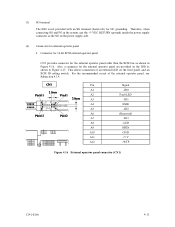
... (fasten tab) for the external operator panel are provided on the IDD as shown in Figure 4.16. Also, a connector for DC grounding. This allows connection of the external operator panel, see Subsection 4.3.4. Pin Signal A1 -ID0 A2 Fault LED A3 -ID1 A4 ESID A5 -ID2 A6 (Reserved) A7 -ID3... A8 -LED A9 OPEN A10 GND A11 +5 V A12 -WTP Figure 4.16 External operator panel connector (CN1) C141-E166 4-13 Therefore, when connecting SG and FG in the system, use the +5 VDC RETURN (ground) inside the power supply connector as shown in Figure 4.17.
... (fasten tab) for the external operator panel are provided on the IDD as shown in Figure 4.16. Also, a connector for DC grounding. This allows connection of the external operator panel, see Subsection 4.3.4. Pin Signal A1 -ID0 A2 Fault LED A3 -ID1 A4 ESID A5 -ID2 A6 (Reserved) A7 -ID3... A8 -LED A9 OPEN A10 GND A11 +5 V A12 -WTP Figure 4.16 External operator panel connector (CN1) C141-E166 4-13 Therefore, when connecting SG and FG in the system, use the +5 VDC RETURN (ground) inside the power supply connector as shown in Figure 4.17.
Manual/User Guide
Page 68
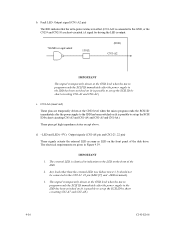
...21, 22 pin) These signals actuate the external LED as same as LED on the front of the disk drive. Any load other than the external LED (see Subsection 4.3.5) should not be connected to set up the SCSI ID by short circuiting CN1-A1 and CN1-A2.) c. The electrical requirements are ...get high impedance status except above. CN1-A6 (reserved) These pins are given in effect (CN1-A12 is connected to the GND, or the CN2-9 and CN2-10 are short-circuited.) A signal for driving the LED is output. 74LS06 or equivalent 150 Ω (IDD) CN1-A2 IMPORTANT This signal is temporarily ...
...21, 22 pin) These signals actuate the external LED as same as LED on the front of the disk drive. Any load other than the external LED (see Subsection 4.3.5) should not be connected to set up the SCSI ID by short circuiting CN1-A1 and CN1-A2.) c. The electrical requirements are ...get high impedance status except above. CN1-A6 (reserved) These pins are given in effect (CN1-A12 is connected to the GND, or the CN2-9 and CN2-10 are short-circuited.) A signal for driving the LED is output. 74LS06 or equivalent 150 Ω (IDD) CN1-A2 IMPORTANT This signal is temporarily ...
Manual/User Guide
Page 69
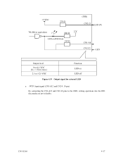
C141-E166 4-17 Figure 4.19 Output signal for external LED e. -WTP: Input signal (CN1-A12 and CN2-9, 10 pin) By connecting the CN1-A12 and CN2-10 pins to the GND, writing operations into the IDD disc media are set to disable.
C141-E166 4-17 Figure 4.19 Output signal for external LED e. -WTP: Input signal (CN1-A12 and CN2-9, 10 pin) By connecting the CN1-A12 and CN2-10 pins to the GND, writing operations into the IDD disc media are set to disable.
Manual/User Guide
Page 70
Recommended components for cable connection between the IDD, host system, and power supply unit are listed in Figure 4.20. External operator panel (example) Figure 4.20 SCSI cables connection 4-18 C141-E166 (6) Cable connection requirements The requirements for connection are given in Table 4.2.
Recommended components for cable connection between the IDD, host system, and power supply unit are listed in Figure 4.20. External operator panel (example) Figure 4.20 SCSI cables connection 4-18 C141-E166 (6) Cable connection requirements The requirements for connection are given in Table 4.2.
Manual/User Guide
Page 72
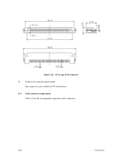
Figure 4.22 SCA2 type SCSI connector (3) Connector for external operator panel This connector is not available for NC model drives. 4.3.3 Cable connector requirements Table 4.2 lists the recommended components cable connection. 4-20 C141-E166
Figure 4.22 SCA2 type SCSI connector (3) Connector for external operator panel This connector is not available for NC model drives. 4.3.3 Cable connector requirements Table 4.2 lists the recommended components cable connection. 4-20 C141-E166


