

Manual/User Guide
Page 2
...without further notice and without prior notice. IMPORTANT NOTE TO USERS READ THE ENTIRE MANUAL CAREFULLY BEFORE USING THIS PRODUCT. In addition, FUJITSU assumes no liability to their property. FUJITSU reserves the right to make changes to any error or omission contained in this ...the accuracy of all information in any other cause. Use the product according to consult our sales representative before using this manual, FUJITSU assumes no liability with the descriptions or instructions contained herein; This product is designed and manufactured for use in accordance with...
...without further notice and without prior notice. IMPORTANT NOTE TO USERS READ THE ENTIRE MANUAL CAREFULLY BEFORE USING THIS PRODUCT. In addition, FUJITSU assumes no liability to their property. FUJITSU reserves the right to make changes to any error or omission contained in this ...the accuracy of all information in any other cause. Use the product according to consult our sales representative before using this manual, FUJITSU assumes no liability with the descriptions or instructions contained herein; This product is designed and manufactured for use in accordance with...
Manual/User Guide
Page 4
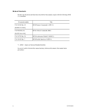
Related Standards Product specifications and functions described in this manual takes precedence. ii C141-E166 Document number T10/1236D Rev.20 [NCITS.351:2001] T10/996D Rev.8c [NCITS.306:1998] T10/1157D Rev.20 T10/1365D Rev.7 Title SCSI Primary Commands-2 (SPC-2) SCSI-3 Block Commands (SBC) SCSI Architecture Model-2 (SAM-2) SCSI Parallel Interface-4 (SPI-4) *1 ANSI = American National Standard Institute In case of conflict between this manual and any referenced document, this manual comply with the following ANSI (*1) standards.
Related Standards Product specifications and functions described in this manual takes precedence. ii C141-E166 Document number T10/1236D Rev.20 [NCITS.351:2001] T10/996D Rev.8c [NCITS.306:1998] T10/1157D Rev.20 T10/1365D Rev.7 Title SCSI Primary Commands-2 (SPC-2) SCSI-3 Block Commands (SBC) SCSI Architecture Model-2 (SAM-2) SCSI Parallel Interface-4 (SPI-4) *1 ANSI = American National Standard Institute In case of conflict between this manual and any referenced document, this manual comply with the following ANSI (*1) standards.
Manual/User Guide
Page 5
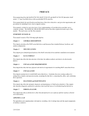
... chapter also describes diagnostic methods for installing it into a host computer system. PREFACE This manual describes the MAP3147NC/NP, MAP3735NC/NP and MAP3367NC/NP (hereafter, MAP series), 3.5 type fixed disk drives with an embedded SCSI controller. Chapter 6 DIAGNOSIS and MAINTENANCE This chapter describes the automatic diagnosis, and maintenance of interface connector. APPENDIX A to...
... chapter also describes diagnostic methods for installing it into a host computer system. PREFACE This manual describes the MAP3147NC/NP, MAP3735NC/NP and MAP3367NC/NP (hereafter, MAP series), 3.5 type fixed disk drives with an embedded SCSI controller. Chapter 6 DIAGNOSIS and MAINTENANCE This chapter describes the automatic diagnosis, and maintenance of interface connector. APPENDIX A to...
Manual/User Guide
Page 6
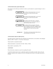
...that personal injury will occur if the user does not perform the procedure correctly. CONVENTIONS USED IN THIS MANUAL The MAP3147NC/NP, MAP3735NC/NP and MAP3367NC/NP disk drives are needed. Hexadecimal number is represented normally. Please write your opinions or requests on the Comment at ...the back of this manual and forward it to the address described in this manual. Decimal number is represented as X'17B9', ...
...that personal injury will occur if the user does not perform the procedure correctly. CONVENTIONS USED IN THIS MANUAL The MAP3147NC/NP, MAP3735NC/NP and MAP3367NC/NP disk drives are needed. Hexadecimal number is represented normally. Please write your opinions or requests on the Comment at ...the back of this manual and forward it to the address described in this manual. Decimal number is represented as X'17B9', ...
Manual/User Guide
Page 7
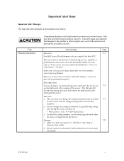
...the power is turned on .(except NC model) C141-E166 v The user must not change the setting of terminals not described 5-5 in this manual are applied for their ECC. Damage 5-11 1. Do not change the setting of read sector keeps allowable error byte number, correction is off... before connecting or disconnecting cables. 2. Hot temperature To prevent injury, do not handle the drive until after the device has 5-1 cooled sufficiently after turning off the power. To short the setting terminal, use the short plug attached when...
...the power is turned on .(except NC model) C141-E166 v The user must not change the setting of terminals not described 5-5 in this manual are applied for their ECC. Damage 5-11 1. Do not change the setting of read sector keeps allowable error byte number, correction is off... before connecting or disconnecting cables. 2. Hot temperature To prevent injury, do not handle the drive until after the device has 5-1 cooled sufficiently after turning off the power. To short the setting terminal, use the short plug attached when...
Manual/User Guide
Page 19
...The flexibility and expandability of the SCSI, as well as described in the ANSI SCSI SPI-4 [T10/1365D Rev.7] to the extent described in this manual. The MAP series disk drives support the Small Computer System Interface (SCSI) as the powerful command set of the MAP series intelligent disk... drives (IDD). CHAPTER 1 GENERAL DESCRIPTION 1.1 Standard Features 1.2 Hardware Structure 1.3 System Configuration This chapter describes the feature and configuration of the IDD, allow the user to...
...The flexibility and expandability of the SCSI, as well as described in the ANSI SCSI SPI-4 [T10/1365D Rev.7] to the extent described in this manual. The MAP series disk drives support the Small Computer System Interface (SCSI) as the powerful command set of the MAP series intelligent disk... drives (IDD). CHAPTER 1 GENERAL DESCRIPTION 1.1 Standard Features 1.2 Hardware Structure 1.3 System Configuration This chapter describes the feature and configuration of the IDD, allow the user to...
Manual/User Guide
Page 48
... execution. 3-12 C141-E166 Figure 3.7 is examples of the alternate block to the adjacent logical data blocks. The logical data block is allocated to OEM Manual-SCSI Logical Specifications-for details of specifications on these commands. When they are allocated to spare sectors which processes several logical data blocks is specified...
... execution. 3-12 C141-E166 Figure 3.7 is examples of the alternate block to the adjacent logical data blocks. The logical data block is allocated to OEM Manual-SCSI Logical Specifications-for details of specifications on these commands. When they are allocated to spare sectors which processes several logical data blocks is specified...
Manual/User Guide
Page 106
... and test equipment Disk drive troubleshooting and repair in item (2) after the drive is indicated. A2 Revising at field Rev. This manual does not describe the factory-level tools and test equipment. 6.2.6 Tests This disk drive can be tested in which the new revision number is shipped from the factory, Fujitsu issues "Engineering Change Request...
... and test equipment Disk drive troubleshooting and repair in item (2) after the drive is indicated. A2 Revising at field Rev. This manual does not describe the factory-level tools and test equipment. 6.2.6 Tests This disk drive can be tested in which the new revision number is shipped from the factory, Fujitsu issues "Engineering Change Request...
Manual/User Guide
Page 108
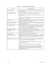
... Operation test While the host computer is posted to see whether the error was caused by the host system. An error posted in this manual. 6-12 C141-E166 Then, look for a possibly faulty subassembly or part of functions. Possible causes include insufficient power capacity, loose cable .... 6.3 Operation Check 6.3.1 Initial seek operation check If an error is detected during initialization by the error detection circuit of the disk drive, an interrupt occurs. The MCU stops the currently processed command, and causes the CHECK CONDITION status to post the error to collect ...
... Operation test While the host computer is posted to see whether the error was caused by the host system. An error posted in this manual. 6-12 C141-E166 Then, look for a possibly faulty subassembly or part of functions. Possible causes include insufficient power capacity, loose cable .... 6.3 Operation Check 6.3.1 Initial seek operation check If an error is detected during initialization by the error detection circuit of the disk drive, an interrupt occurs. The MCU stops the currently processed command, and causes the CHECK CONDITION status to post the error to collect ...
Manual/User Guide
Page 110
...maximum ripple peak-to the hardware and software manuals supplied with the system. 6-14 C141-E166 For a star-burst connection, check that the terminating resistor is correctly mounted on the PCA are connected correctly. Check that all disk drives. When possible, execute the system level diagnostic... routine as explained in the host computer manual. This gives a detailed report of the power connector) is 4.75 to 12.6 VDC. ...
...maximum ripple peak-to the hardware and software manuals supplied with the system. 6-14 C141-E166 For a star-burst connection, check that the terminating resistor is correctly mounted on the PCA are connected correctly. Check that all disk drives. When possible, execute the system level diagnostic... routine as explained in the host computer manual. This gives a detailed report of the power connector) is 4.75 to 12.6 VDC. ...
Manual/User Guide
Page 112
6.4.4 Troubleshooting with parts replacement in Subsection 6.4.2. This manual does not cover finding possibly faulty parts at the factory level. 6.4.5 Finding possibly faulty parts Finding possibly faulty parts in the field was explained in the factory This manual does not cover troubleshooting at the factory level. 6-16 C141-E166
6.4.4 Troubleshooting with parts replacement in Subsection 6.4.2. This manual does not cover finding possibly faulty parts at the factory level. 6.4.5 Finding possibly faulty parts Finding possibly faulty parts in the field was explained in the factory This manual does not cover troubleshooting at the factory level. 6-16 C141-E166

Manual/User Guide
Page 127
... TEL: 81-44-754-2130 FAX: 81-44-754-8346 FUJITSU COMPUTER PRODUCTS OF AMERICA, INC. 2904 Orchard Parkway, San Jose, California 95134-2009, U.S.A. Via Nazario Sauro, 38 20099 Sesto S. Comments concerning this manual can be directed to one of KOREA TEL: 82-2-3787-6000... FAX: 82-2-3787-6029 FUJITSU COMPUTERS (SINGAPORE) PTE. Giovanni (MI), ITALY TEL: 39-2-26294-1 FAX: 39-2-26294-201 FUJITSU FRANCE S.A. 1, Place des Etats-Unis, SILIC 310,...
... TEL: 81-44-754-2130 FAX: 81-44-754-8346 FUJITSU COMPUTER PRODUCTS OF AMERICA, INC. 2904 Orchard Parkway, San Jose, California 95134-2009, U.S.A. Via Nazario Sauro, 38 20099 Sesto S. Comments concerning this manual can be directed to one of KOREA TEL: 82-2-3787-6000... FAX: 82-2-3787-6029 FUJITSU COMPUTERS (SINGAPORE) PTE. Giovanni (MI), ITALY TEL: 39-2-26294-1 FAX: 39-2-26294-201 FUJITSU FRANCE S.A. 1, Place des Etats-Unis, SILIC 310,...


