
Manual/User Guide
Page 7
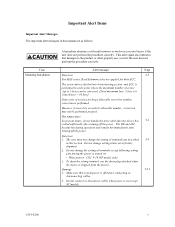
... user does not perform the procedure correctly. Data loss 1. The user must not change the setting of terminals except following setting pins during operation and remain hot immediately after turning off the power. Damage 5-11 1. Important Alert Items Important Alert Messages The important... alert messages in this section. Hot temperature To prevent injury, do not handle the drive until after the device has 5-1 cooled sufficiently after turning off the power. Make sure that damages to 5 byte) can be performed ...
... user does not perform the procedure correctly. Data loss 1. The user must not change the setting of terminals except following setting pins during operation and remain hot immediately after turning off the power. Damage 5-11 1. Important Alert Items Important Alert Messages The important... alert messages in this section. Hot temperature To prevent injury, do not handle the drive until after the device has 5-1 cooled sufficiently after turning off the power. Make sure that damages to 5 byte) can be performed ...
Manual/User Guide
Page 8
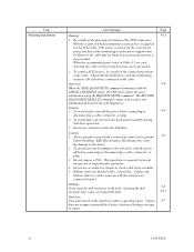
... connected to pin 1. To avoid injury, do not touch the mechanical assembly during servicing or repair. Caution 1. ESD (Electrostatics Discharge) may be blown or the cable may cause the damage to a cable connector with the terminating resistor is turned on the disk drive before connecting ...the system in the field. To avoid shocks, turn the power off the power before requesting repair. Fujitsu 6-7 does not assume responsibility if data is required to the disk drive, turn off before handling. When the recommended parts listed in Table 4.2 are marked with a wrist ...
... connected to pin 1. To avoid injury, do not touch the mechanical assembly during servicing or repair. Caution 1. ESD (Electrostatics Discharge) may be blown or the cable may cause the damage to a cable connector with the terminating resistor is turned on the disk drive before connecting ...the system in the field. To avoid shocks, turn the power off the power before requesting repair. Fujitsu 6-7 does not assume responsibility if data is required to the disk drive, turn off before handling. When the recommended parts listed in Table 4.2 are marked with a wrist ...
Manual/User Guide
Page 11
... 3.3.1 Defect list ...3-11 3.3.2 Alternate block allocation 3-11 CHAPTER 4 INSTALLATION REQUIREMENTS 4-1 4.1 Mounting Requirements ...4-1 4.1.1 External dimensions ...4-1 4.1.2 Mounting ...4-4 4.1.3 Notes on mounting ...4-4 4.2 Power Supply Requirements 4-8 4.3 Connection Requirements 4-11 4.3.1 68 pin connector 16-bit SCSI model (NP model 4-11 C141-E166 ix
... 3.3.1 Defect list ...3-11 3.3.2 Alternate block allocation 3-11 CHAPTER 4 INSTALLATION REQUIREMENTS 4-1 4.1 Mounting Requirements ...4-1 4.1.1 External dimensions ...4-1 4.1.2 Mounting ...4-4 4.1.3 Notes on mounting ...4-4 4.2 Power Supply Requirements 4-8 4.3 Connection Requirements 4-11 4.3.1 68 pin connector 16-bit SCSI model (NP model 4-11 C141-E166 ix
Manual/User Guide
Page 13
... 6.4.1 6.4.2 6.4.3 6.4.4 6.4.5 Diagnostic test ...6-12 Troubleshooting Procedures 6-13 Outline of troubleshooting procedures 6-13 Troubleshooting with disk drive replacement in the field 6-13 Troubleshooting at the repair site 6-15 Troubleshooting with parts replacement in the factory 6-16 ... 7-4 APPENDIX A SETTING TERMINALS A-1 A.1 Setting Terminals (on NP model only A-2 APPENDIX B CONNECTOR SIGNAL ALLOCATION B-1 B.1 SCSI Connector Signal Allocation: 68 pin type LVD 16-bit SCSI B-2 B.2 SCSI Connector Signal Allocation: SCA2 type LVD 16-bit SCSI B-3 INDEX ...IN-1 C141-E166 xi
... 6.4.1 6.4.2 6.4.3 6.4.4 6.4.5 Diagnostic test ...6-12 Troubleshooting Procedures 6-13 Outline of troubleshooting procedures 6-13 Troubleshooting with disk drive replacement in the field 6-13 Troubleshooting at the repair site 6-15 Troubleshooting with parts replacement in the factory 6-16 ... 7-4 APPENDIX A SETTING TERMINALS A-1 A.1 Setting Terminals (on NP model only A-2 APPENDIX B CONNECTOR SIGNAL ALLOCATION B-1 B.1 SCSI Connector Signal Allocation: 68 pin type LVD 16-bit SCSI B-2 B.2 SCSI Connector Signal Allocation: SCA2 type LVD 16-bit SCSI B-3 INDEX ...IN-1 C141-E166 xi
Manual/User Guide
Page 17
... model only 5-10 Table 6.1 Self-diagnostic functions ...6-1 Table 6.2 System-level field troubleshooting 6-14 Table 6.3 Disk drive troubleshooting ...6-15 Table 7.1 Definition of sense data ...7-3 Table A.1 CN2 setting terminal (on NP model drives only A-2 Table B.1 SCSI connector (68 pin type LVD 16-bit SCSI): CN1 B-2 Table B.2 SCSI connector (SCA2 type LVD 16-bit SCSI): CN1...
... model only 5-10 Table 6.1 Self-diagnostic functions ...6-1 Table 6.2 System-level field troubleshooting 6-14 Table 6.3 Disk drive troubleshooting ...6-15 Table 7.1 Definition of sense data ...7-3 Table A.1 CN2 setting terminal (on NP model drives only A-2 Table B.1 SCSI connector (68 pin type LVD 16-bit SCSI): CN1 B-2 Table B.2 SCSI connector (SCA2 type LVD 16-bit SCSI): CN1...
Manual/User Guide
Page 29
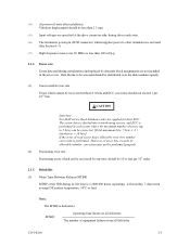
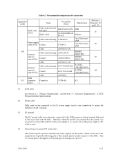
... order numbers Model name MAP3147NC MAP3147NP MAP3735NC MAP3735NP MAP3367NC MAP3367NP Order number CA06200-B400 CA06200-B460 CA06200-B200 CA06200-B260 CA06200-B100 CA06200-B160 SCSI type SCA2, LVD 68-pin, LVD SCA2, LVD 68-pin, LVD SCA2, LVD 68-pin, LVD Capacity Number of Number of the SCSI... This chapter describes specifications of the IDD and the functional specifications of Mounting (user area) disks heads screw 147.01 GB 4 8 73.50 GB 2 4 #6-32UNC 36.74 GB 1 2 The data format can be changed by reinitializing with the user's system. C141-E166 2-1 Table 2.1 lists ...
... order numbers Model name MAP3147NC MAP3147NP MAP3735NC MAP3735NP MAP3367NC MAP3367NP Order number CA06200-B400 CA06200-B460 CA06200-B200 CA06200-B260 CA06200-B100 CA06200-B160 SCSI type SCA2, LVD 68-pin, LVD SCA2, LVD 68-pin, LVD SCA2, LVD 68-pin, LVD Capacity Number of Number of the SCSI... This chapter describes specifications of the IDD and the functional specifications of Mounting (user area) disks heads screw 147.01 GB 4 8 73.50 GB 2 4 #6-32UNC 36.74 GB 1 2 The data format can be changed by reinitializing with the user's system. C141-E166 2-1 Table 2.1 lists ...
Manual/User Guide
Page 31
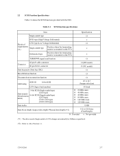
... up to 1.5 m. (*8) 1 on 1 connection case. (*9) 1 host, 15 devices case. (*10) The maximum data transfer rate may be changed by transmission characteristics. (*11) The terminator power pin (SCSI connector) which supplies power to other terminators is not used.
... up to 1.5 m. (*8) 1 on 1 connection case. (*9) 1 host, 15 devices case. (*10) The maximum data transfer rate may be changed by transmission characteristics. (*11) The terminator power pin (SCSI connector) which supplies power to other terminators is not used.
Manual/User Guide
Page 33
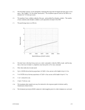
... in the error rate. The sector-data is divided into 6 interleaving sectors, and ECC is defined as: MTBF= Operating time (hours) at the drive connector side, during drive ready state. (*6) The terminator power pin (SCSI connector) which supplies power to 5 byte) can be recovered by alternate block assignments are applied for their ECC.
... in the error rate. The sector-data is divided into 6 interleaving sectors, and ECC is defined as: MTBF= Operating time (hours) at the drive connector side, during drive ready state. (*6) The terminator power pin (SCSI connector) which supplies power to 5 byte) can be recovered by alternate block assignments are applied for their ECC.
Manual/User Guide
Page 35
... on the PCA × Differential type Position where the terminating resistor is mounted on the PCA × TERMPWR signal send function Ο Connector 68 pin P cable connector 80 pin SCA2 connector Ο (NP model) Ο (NC model) Data bus parity (Data bus CRC) Ο Bus arbitration function Ο Disconnection/reconnection function...
... on the PCA × Differential type Position where the terminating resistor is mounted on the PCA × TERMPWR signal send function Ο Connector 68 pin P cable connector 80 pin SCA2 connector Ο (NP model) Ο (NC model) Data bus parity (Data bus CRC) Ο Bus arbitration function Ο Disconnection/reconnection function...

Manual/User Guide
Page 60
... the power on the SCSI bus, the requirements for +5 VDC given in Figure 4.9 must be satisfied between the IDD and at the power supply connector pin of the IDD (receiving end) must satisfy the requirement given in Subsection 2.1.3. (For other requirements, see Items (4) and (5) below.) (2) Current waveform (reference) Figure 4.8 shows the...
... the power on the SCSI bus, the requirements for +5 VDC given in Figure 4.9 must be satisfied between the IDD and at the power supply connector pin of the IDD (receiving end) must satisfy the requirement given in Subsection 2.1.3. (For other requirements, see Items (4) and (5) below.) (2) Current waveform (reference) Figure 4.8 shows the...
Manual/User Guide
Page 63
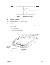
Figure 4.12 AC noise filter (recommended) 4.3 Connection Requirements 4.3.1 68 pin connector 16-bit SCSI model (NP model) (1) Connectors Figures 4.13 show the locations of connectors and terminals on the 68 pin connector type 16-bit SCSI (MP) model. • Power supply connector • SCSI connector • External operator panel connector External operator panel connector (CN2) Power supply connector (CN1) External operator panel connector (CN1) SCSI connector (CN1) Figure 4.13 NP connectors and terminals location C141-E166 4-11
Figure 4.12 AC noise filter (recommended) 4.3 Connection Requirements 4.3.1 68 pin connector 16-bit SCSI model (NP model) (1) Connectors Figures 4.13 show the locations of connectors and terminals on the 68 pin connector type 16-bit SCSI (MP) model. • Power supply connector • SCSI connector • External operator panel connector External operator panel connector (CN2) Power supply connector (CN1) External operator panel connector (CN1) SCSI connector (CN1) Figure 4.13 NP connectors and terminals location C141-E166 4-11
Manual/User Guide
Page 64
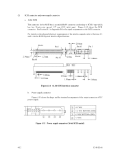
... 1.4 in Appendix B for the SCSI bus is an unshielded P connector conforming to SCSI-3 type which has two 34-pin rows spaced 1.27 mm (0.05 inch) apart. Pin 34 Pin 1 2.00mm Pin A1 Pin 1 2.54mm Pin 68 1.27mm Pin 35 2.00m Pin A2 5.08mm 0.40mm 0.635mm 0.40mm 1.00mm 1.30mm Figure 4.14 16-bit SCSI interface connector 5.08mm b. (2) SCSI connector...
... 1.4 in Appendix B for the SCSI bus is an unshielded P connector conforming to SCSI-3 type which has two 34-pin rows spaced 1.27 mm (0.05 inch) apart. Pin 34 Pin 1 2.00mm Pin A1 Pin 1 2.54mm Pin 68 1.27mm Pin 35 2.00m Pin A2 5.08mm 0.40mm 0.635mm 0.40mm 1.00mm 1.30mm Figure 4.14 16-bit SCSI interface connector 5.08mm b. (2) SCSI connector...
Manual/User Guide
Page 65
...) for the external operator panel other than the SCSI bus as shown in Figure 4.16. This allows connection of the external operator panel, see Subsection 4.3.4. Pin Signal A1 -ID0 A2 Fault LED A3 -ID1 A4 ESID A5 -ID2 A6 (Reserved) A7 -ID3 A8 -LED A9 OPEN A10 GND A11 +5 V A12 -WTP...
...) for the external operator panel other than the SCSI bus as shown in Figure 4.16. This allows connection of the external operator panel, see Subsection 4.3.4. Pin Signal A1 -ID0 A2 Fault LED A3 -ID1 A4 ESID A5 -ID2 A6 (Reserved) A7 -ID3 A8 -LED A9 OPEN A10 GND A11 +5 V A12 -WTP...
Manual/User Guide
Page 67
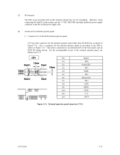
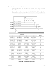
Figure 4.18 shows the electrical requirements. Figure 4.18 16-bit SCSI ID external input C141-E166 4-15 (5) External operator panel connector Signals a. 16-bit SCSI -ID3, -ID2, -ID1, -ID0: Input signals (CN1-A1, A3, A5, A7 pin and CN2-02, 04, 06, 08 pin) These signals are used for providing switches to set the SCSI ID of the IDD externally. For the recommended circuit examples, see Subsection 4.3.4.
Figure 4.18 shows the electrical requirements. Figure 4.18 16-bit SCSI ID external input C141-E166 4-15 (5) External operator panel connector Signals a. 16-bit SCSI -ID3, -ID2, -ID1, -ID0: Input signals (CN1-A1, A3, A5, A7 pin and CN2-02, 04, 06, 08 pin) These signals are used for providing switches to set the SCSI ID of the IDD externally. For the recommended circuit examples, see Subsection 4.3.4.
Manual/User Guide
Page 68
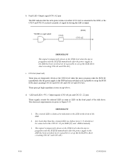
... when the micro program reads the SCSI ID immediately after the power supply to the IDD has been switched on the front of the disk drive. The electrical requirements are given in indication to set up the SCSI ID by short circuiting CN1-A1 and CN1-A2.) c. CN1-A6 (reserved) These... pins are short-circuited.) A signal for driving the LED is output. 74LS06 or equivalent 150 Ω (IDD) CN1-A2 IMPORTANT This signal is temporarily driven at the GND level...
... when the micro program reads the SCSI ID immediately after the power supply to the IDD has been switched on the front of the disk drive. The electrical requirements are given in indication to set up the SCSI ID by short circuiting CN1-A1 and CN1-A2.) c. CN1-A6 (reserved) These... pins are short-circuited.) A signal for driving the LED is output. 74LS06 or equivalent 150 Ω (IDD) CN1-A2 IMPORTANT This signal is temporarily driven at the GND level...
Manual/User Guide
Page 69
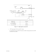
Figure 4.19 Output signal for external LED e. -WTP: Input signal (CN1-A12 and CN2-9, 10 pin) By connecting the CN1-A12 and CN2-10 pins to the GND, writing operations into the IDD disc media are set to disable. C141-E166 4-17
Figure 4.19 Output signal for external LED e. -WTP: Input signal (CN1-A12 and CN2-9, 10 pin) By connecting the CN1-A12 and CN2-10 pins to the GND, writing operations into the IDD disc media are set to disable. C141-E166 4-17
Manual/User Guide
Page 71
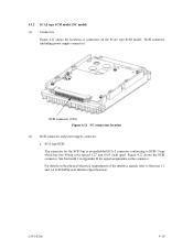
...) (1) Connectors Figure 4.21 shows the locations of connectors on the physical/electrical requirements of the interface signals, refer to SCSI-3 type which has two 40-pin rows spaced 1.27 mm (0.05 inch) apart. SCA type SCSI The connector for signal assignments on the connector. For details on the SCA2 type SCSI...
...) (1) Connectors Figure 4.21 shows the locations of connectors on the physical/electrical requirements of the interface signals, refer to SCSI-3 type which has two 40-pin rows spaced 1.27 mm (0.05 inch) apart. SCA type SCSI The connector for signal assignments on the connector. For details on the SCA2 type SCSI...
Manual/User Guide
Page 73
...1-480424-0 Tyco Electronics AMP 170148-1 Tyco Electronics AMP (AWG18 to 24) A3B-12D-2C HIROSE ELECTRIC A3B-2630SCC HIROSE ELECTRIC (AWG26 to 36) FCN-723J024/2M FUJITSU TAKAMIZAWA FCN-723J-G/AM FUJITSU TAKAMIZAWA (AWG28) 71780-003 FCI Reference (Figures 4.25 and 4.30) S1 S2 S3 S4 (1) SCSI cable See Section 1.3, "Physical ... connect SG of the power supply to SG is provided with the IDD. When connection is not required, leave open the following pins in the external operator panel connector of the IDD : Pins 21, 22 and pins 01 through 08 in CN2 and pins A1 through A12 in CN1.
...1-480424-0 Tyco Electronics AMP 170148-1 Tyco Electronics AMP (AWG18 to 24) A3B-12D-2C HIROSE ELECTRIC A3B-2630SCC HIROSE ELECTRIC (AWG26 to 36) FCN-723J024/2M FUJITSU TAKAMIZAWA FCN-723J-G/AM FUJITSU TAKAMIZAWA (AWG28) 71780-003 FCI Reference (Figures 4.25 and 4.30) S1 S2 S3 S4 (1) SCSI cable See Section 1.3, "Physical ... connect SG of the power supply to SG is provided with the IDD. When connection is not required, leave open the following pins in the external operator panel connector of the IDD : Pins 21, 22 and pins 01 through 08 in CN2 and pins A1 through A12 in CN1.
Manual/User Guide
Page 76
... environment must satisfy the requirements specified in Subsection 2.1.3 when the drive is up. (2) Unpackaging a) Use a flat work for replacing. (4) Packaging a) Store the drive in an antistatic vinyl pack. The only pin settings that may be used, use one of the package so... that they will not get lost or damaged. d) Keep a record of the DE and screws. (3) Installation/removal/replacement a) Do not attempt to the PCAs and interface connector when removing the drive from direct shocks. Check that the drive is on hard...
... environment must satisfy the requirements specified in Subsection 2.1.3 when the drive is up. (2) Unpackaging a) Use a flat work for replacing. (4) Packaging a) Store the drive in an antistatic vinyl pack. The only pin settings that may be used, use one of the package so... that they will not get lost or damaged. d) Keep a record of the DE and screws. (3) Installation/removal/replacement a) Do not attempt to the PCAs and interface connector when removing the drive from direct shocks. Check that the drive is on hard...

Manual/User Guide
Page 79
CAUTION Data loss 1. Do not change the setting of setting terminal. Pin 2 Pin 24 CN2 Pin 1 Pin 23 Figure 5.2 Setting terminals location (on . • Write protect: CN2 9-10 (NP model only) 3. Figures 5.3 shows the allocation and default settings. The user must not ... terminal, use the short plug attached when the device is turned on NP models only) C141-E166 5-5 5.3 Setting Terminals A user sets up the following setting pins during the power is shipped from the factory.
CAUTION Data loss 1. Do not change the setting of setting terminal. Pin 2 Pin 24 CN2 Pin 1 Pin 23 Figure 5.2 Setting terminals location (on . • Write protect: CN2 9-10 (NP model only) 3. Figures 5.3 shows the allocation and default settings. The user must not ... terminal, use the short plug attached when the device is turned on NP models only) C141-E166 5-5 5.3 Setting Terminals A user sets up the following setting pins during the power is shipped from the factory.