Manual/User Guide
Page 4
Related Standards Specifications and functions of the Small Computer System Interface (SCSI) American National Standards Institute (ANSI) WORKING DRAFT Information Technology SCSI-3 Parallel Interface American National Standards Institute (...
Related Standards Specifications and functions of the Small Computer System Interface (SCSI) American National Standards Institute (ANSI) WORKING DRAFT Information Technology SCSI-3 Parallel Interface American National Standards Institute (...
Manual/User Guide
Page 5
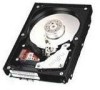
... features, hardware, and system configuration. Chapter 2 SPECIFICATIONS This chapter gives detailed specifications of MAN series. PREFACE This manual describes the MAN3735MC/MP, MAN3367MC/MP, MAN3184MC/MP (hereafter, MAN series), 3.5 type fixed disk drives with an embedded SCSI controller. This manual details the specifications and functions of troubleshooting the disk drives. Chapter 5 INSTALLATION This chapter explains how...
... features, hardware, and system configuration. Chapter 2 SPECIFICATIONS This chapter gives detailed specifications of MAN series. PREFACE This manual describes the MAN3735MC/MP, MAN3367MC/MP, MAN3184MC/MP (hereafter, MAN series), 3.5 type fixed disk drives with an embedded SCSI controller. This manual details the specifications and functions of troubleshooting the disk drives. Chapter 5 INSTALLATION This chapter explains how...
Manual/User Guide
Page 10
General Description 2. Diagnostics and Maintenance 7. Error Analysis 8. SCSI Bus 2. Installation Requirements 5. SCSI Bus Error Recovery Processing SCSI Logical Interface Specifications 1. Specifications 3. SCSI Message 3. Command Processing 2. Installation 6. Data Format 4. Principle of Operation SCSI Physical Interface Specifications 1. MANUAL ORGANIZATION PRODUCT/ MAINTENANCE MANUAL (This manual) 1. Command Specification 4. Disk Medium Management viii C141-E128-01EN Sense Data and error Recovery Procedure 5. Data Buffer Management 3.
General Description 2. Diagnostics and Maintenance 7. Error Analysis 8. SCSI Bus 2. Installation Requirements 5. SCSI Bus Error Recovery Processing SCSI Logical Interface Specifications 1. Specifications 3. SCSI Message 3. Command Processing 2. Installation 6. Data Format 4. Principle of Operation SCSI Physical Interface Specifications 1. MANUAL ORGANIZATION PRODUCT/ MAINTENANCE MANUAL (This manual) 1. Command Specification 4. Disk Medium Management viii C141-E128-01EN Sense Data and error Recovery Procedure 5. Data Buffer Management 3.
Manual/User Guide
Page 11
CONTENTS page CHAPTER 1 GENERAL DESCRIPTION 1-1 1.1 Standard Features ...1-2 1.2 Hardware Structure...1-5 1.3 System Configuration ...1-8 CHAPTER 2 SPECIFICATIONS 2-1 2.1 Hardware Specifications 2-1 2.1.1 Model name and part number 2-1 2.1.2 Function specifications ...2-2 2.1.3 Environmental specifications 2-4 2.1.4 Error rate...2-5 2.1.5 Reliability ...2-5 2.2 SCSI Function Specifications 2-7 CHAPTER 3 DATA FORMAT 3-1 3.1 Data Space ...3-1 3.1.1 Cylinder configuration...3-1 3.1.2 Alternate spare area ...3-4 3.1.3 Track format ...3-5 3.1.4 Sector format ...3-7 3.1.5 Format capacity ...
CONTENTS page CHAPTER 1 GENERAL DESCRIPTION 1-1 1.1 Standard Features ...1-2 1.2 Hardware Structure...1-5 1.3 System Configuration ...1-8 CHAPTER 2 SPECIFICATIONS 2-1 2.1 Hardware Specifications 2-1 2.1.1 Model name and part number 2-1 2.1.2 Function specifications ...2-2 2.1.3 Environmental specifications 2-4 2.1.4 Error rate...2-5 2.1.5 Reliability ...2-5 2.2 SCSI Function Specifications 2-7 CHAPTER 3 DATA FORMAT 3-1 3.1 Data Space ...3-1 3.1.1 Cylinder configuration...3-1 3.1.2 Alternate spare area ...3-4 3.1.3 Track format ...3-5 3.1.4 Sector format ...3-7 3.1.5 Format capacity ...
Manual/User Guide
Page 17
... 2.2 Environmental/power requirements 2-4 Table 2.3 SCSI function specifications ...2-7 Table 3.1 Zone layout and track capacity (MAN series 3-3 Table 3.4 Format capacity...3-10 Table 4.1 Surface temperature check point 4-6 Table 4.2 ... DEFINITION command 5-9 Table 5.8 Setting check list (MP model only 5-10 Table 6.1 Self-diagnostic functions...6-1 Table 6.2 System-level field troubleshooting 6-14 Table 6.3 Disk drive troubleshooting...6-15 Table 7.1 Definition of sense data...7-3 Table B.1 Setting terminal: CN2 ...B-2 Table C.1 SCSI connector (SCA2 type LVD 16-bit SCSI): CN1 C-2 Table...
... 2.2 Environmental/power requirements 2-4 Table 2.3 SCSI function specifications ...2-7 Table 3.1 Zone layout and track capacity (MAN series 3-3 Table 3.4 Format capacity...3-10 Table 4.1 Surface temperature check point 4-6 Table 4.2 ... DEFINITION command 5-9 Table 5.8 Setting check list (MP model only 5-10 Table 6.1 Self-diagnostic functions...6-1 Table 6.2 System-level field troubleshooting 6-14 Table 6.3 Disk drive troubleshooting...6-15 Table 7.1 Definition of sense data...7-3 Table B.1 Setting terminal: CN2 ...B-2 Table C.1 SCSI connector (SCA2 type LVD 16-bit SCSI): CN1 C-2 Table...
Manual/User Guide
Page 19
... describes the feature and configuration of the IDD, allow the user to SCSI Logical Interface Specifications for details. The flexibility and expandability of the SCSI, as well as the powerful command set of the intelligent disk drives (IDD). Refer to construct a high-performance reliable disk subsystem with an embedded SCSI controller. The....131 - 1986: Small Computer System Interface (SCSI), ANSI X3.131-1994: Small Computer System Interface - 2 (SCSI-2)]. IDDs are high performance large capacity 3.5 type fixed disk drives with large storage capacity. C141-E128-01EN 1 - 1
... describes the feature and configuration of the IDD, allow the user to SCSI Logical Interface Specifications for details. The flexibility and expandability of the SCSI, as well as the powerful command set of the intelligent disk drives (IDD). Refer to construct a high-performance reliable disk subsystem with an embedded SCSI controller. The....131 - 1986: Small Computer System Interface (SCSI), ANSI X3.131-1994: Small Computer System Interface - 2 (SCSI-2)]. IDDs are high performance large capacity 3.5 type fixed disk drives with large storage capacity. C141-E128-01EN 1 - 1
Manual/User Guide
Page 20
...of system functions. (3) 8-bit SCSI/16-bit SCSI The IDD has 16-bit data bus width (16-bit SCSI), which meets the logical specification of the disk drive. For the ultra SCSI model, number of the host system. (2) SCSI/CCS standard The IDD provides not only SCSI basic functions but also... mode. • 16-bit SCSI: The data transfer rate on the SCSI bus is 160 MB/s maximum in the standard 3.5 type fixed disk drive form factor, the IDD is extremely compact. The IDD can manipulate data through logical block addressing regardless of the physical characteristics of the SCSI CCS...
...of system functions. (3) 8-bit SCSI/16-bit SCSI The IDD has 16-bit data bus width (16-bit SCSI), which meets the logical specification of the disk drive. For the ultra SCSI model, number of the host system. (2) SCSI/CCS standard The IDD provides not only SCSI basic functions but also... mode. • 16-bit SCSI: The data transfer rate on the SCSI bus is 160 MB/s maximum in the standard 3.5 type fixed disk drive form factor, the IDD is extremely compact. The IDD can manipulate data through logical block addressing regardless of the physical characteristics of the SCSI CCS...

Manual/User Guide
Page 29
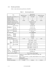
CHAPTER 2 SPECIFICATIONS 2.1 Hardware Specifications 2.2 SCSI Function Specifications This chapter describes specifications of the IDD and the functional specifications of the SCSI. 2.1 Hardware Specifications 2.1.1 Model name and part number Each model has a different recording capacities and interface connector type when shipped. (See Appendix D for the model name (type) and product number.) The data format can be changed by reinitializing with the user's system. C141-E128-01EN 2 - 1
CHAPTER 2 SPECIFICATIONS 2.1 Hardware Specifications 2.2 SCSI Function Specifications This chapter describes specifications of the IDD and the functional specifications of the SCSI. 2.1 Hardware Specifications 2.1.1 Model name and part number Each model has a different recording capacities and interface connector type when shipped. (See Appendix D for the model name (type) and product number.) The data format can be changed by reinitializing with the user's system. C141-E128-01EN 2 - 1
Manual/User Guide
Page 30
... m max (*7) LVD Cable length: 25 m max (*8) Cable length: 12 m max (*9) Data transfer rate (*10) Disk drive SCSI Synchronous mode 52.0 to 528 byte (Fixed length) SCSI command specification ANSI X3.131-1986, ANSI X3.131-1994 and CCS (Rev. 4B) conformity SPC-2 (T10/1236-D Rev 12), SBC (... (*4) Stop time Recording mode External dimensions Height: Width: Depth: Weight (max) Power consumption (*5) Fast 5 SCSI MAN3735 series 73.49 GB 4 8 29,902 9.5 W Specification MAN3367 series 36.74 GB 2 4 29,950 230,400 to 377,344 10,025±0.2% 2.99 msec 0.4 ms/0.6 ms 4.5 ms/5.0 ms 11.0 ms/...
... m max (*7) LVD Cable length: 25 m max (*8) Cable length: 12 m max (*9) Data transfer rate (*10) Disk drive SCSI Synchronous mode 52.0 to 528 byte (Fixed length) SCSI command specification ANSI X3.131-1986, ANSI X3.131-1994 and CCS (Rev. 4B) conformity SPC-2 (T10/1236-D Rev 12), SBC (... (*4) Stop time Recording mode External dimensions Height: Width: Depth: Weight (max) Power consumption (*5) Fast 5 SCSI MAN3735 series 73.49 GB 4 8 29,902 9.5 W Specification MAN3367 series 36.74 GB 2 4 29,950 230,400 to 377,344 10,025±0.2% 2.99 msec 0.4 ms/0.6 ms 4.5 ms/5.0 ms 11.0 ms/...

Manual/User Guide
Page 32
... Random requirements W/R Input power (about 80 (*5) IOPS) Ready +5 VDC ±5% (*6) Random W/R (about 80 IOPS) Ripple (*7) MAN3735 series Specification MAN3367 series 5 to 50°C -10 to 60°C -40 to 60°C MAN3184 series 5 to 55°C 15°C/h or... -60 m to 12,000 m 0.6 A 0.45 A 0.4 A 3.0 A 0.9 A 0.7 A 0.4 A 0.9 A +5 V/+12 V 250 mVp-p 0.6 A (*1) For detail condition, see Section 4.1. (*2) Vibration applied to the drive is measured at near the mounting screw hole on the frame as much as possible. (*3) At random seek write/read and default on retry setting...
... Random requirements W/R Input power (about 80 (*5) IOPS) Ready +5 VDC ±5% (*6) Random W/R (about 80 IOPS) Ripple (*7) MAN3735 series Specification MAN3367 series 5 to 50°C -10 to 60°C -40 to 60°C MAN3184 series 5 to 55°C 15°C/h or... -60 m to 12,000 m 0.6 A 0.45 A 0.4 A 3.0 A 0.9 A 0.7 A 0.4 A 0.9 A +5 V/+12 V 250 mVp-p 0.6 A (*1) For detail condition, see Section 4.1. (*2) Vibration applied to the drive is measured at near the mounting screw hole on the frame as much as possible. (*3) At random seek write/read and default on retry setting...

Manual/User Guide
Page 35
Table 2.3 SCSI function specifications Item Specification Single-ended type Ο HVD type (High Voltage Differential) × LVD type (Low Voltage Differential) Ο Electrical 160/m LVD type (Low Voltage Differential) Ο requirements ... type) Data transfer (LVD type) (Synchronous 16-bit SCSI (Single-Ended type) mode) (LVD type) (160/m LVD type) #0 to (12) of Section 1.1. 2.2 SCSI Function Specifications Table 2.3 shows the SCSI functions provided with the IDD. Data buffer 8 MB (MC/MP) Data block length (Logical data length=Physical data length) (*2) 512 to...
Table 2.3 SCSI function specifications Item Specification Single-ended type Ο HVD type (High Voltage Differential) × LVD type (Low Voltage Differential) Ο Electrical 160/m LVD type (Low Voltage Differential) Ο requirements ... type) Data transfer (LVD type) (Synchronous 16-bit SCSI (Single-Ended type) mode) (LVD type) (160/m LVD type) #0 to (12) of Section 1.1. 2.2 SCSI Function Specifications Table 2.3 shows the SCSI functions provided with the IDD. Data buffer 8 MB (MC/MP) Data block length (Logical data length=Physical data length) (*2) 512 to...

Manual/User Guide
Page 37
... The IDD allocates cylinders to the user's assignment (MODE SELECT command). The system space is the cylinder configuration. Several sectors in the last track of a specific command, but user can be accessed with the logical data block addressing method described in the user space.
... The IDD allocates cylinders to the user's assignment (MODE SELECT command). The system space is the cylinder configuration. Several sectors in the last track of a specific command, but user can be accessed with the logical data block addressing method described in the user space.
Manual/User Guide
Page 48
... of logical data block. (1) Alternate block allocation during the FORMAT UNIT command execution. 3 - 12 C141-E128-01EN Refer to OEM Manual-SCSI Logical Specifications-for details of specifications on the same cylinder as the defective sector's and is effective until all spare sectors in that cylinder are allocated can specify the size...
... of logical data block. (1) Alternate block allocation during the FORMAT UNIT command execution. 3 - 12 C141-E128-01EN Refer to OEM Manual-SCSI Logical Specifications-for details of specifications on the same cylinder as the defective sector's and is effective until all spare sectors in that cylinder are allocated can specify the size...

Manual/User Guide
Page 56
... shown in Figure 4.5, and the tolerance of the angle is ±5° from the IDD frame wall at the corner must be within the device specifications. c) Tightening torque of the system. a) Use the frame with an embossed structure, or the like. d) Impact caused by the electric driver must be secured with...
... shown in Figure 4.5, and the tolerance of the angle is ±5° from the IDD frame wall at the corner must be within the device specifications. c) Tightening torque of the system. a) Use the frame with an embossed structure, or the like. d) Impact caused by the electric driver must be secured with...

Manual/User Guide
Page 58
... at installed in a cabinet is shown in Table 4.1. These measurement results should be within a criteria listed in Figures 4.7. 4 - 6 C141-E128-01EN Measurement point 1 Center of specific ICs and the DE. Confirm the cooling effect by measuring temperature of DE cover 2 Read channel LSI 3 VCM/SPM Driver 4 HDC 5 MPU Criteria 55°... so that the DE surface temperature does not exceed 55°C. • Cool the PCA side especially with ambient temperature measured 3 cm from the disk drive.
... at installed in a cabinet is shown in Table 4.1. These measurement results should be within a criteria listed in Figures 4.7. 4 - 6 C141-E128-01EN Measurement point 1 Center of specific ICs and the DE. Confirm the cooling effect by measuring temperature of DE cover 2 Read channel LSI 3 VCM/SPM Driver 4 HDC 5 MPU Criteria 55°... so that the DE surface temperature does not exceed 55°C. • Cool the PCA side especially with ambient temperature measured 3 cm from the disk drive.

Manual/User Guide
Page 62
... spindle motors should be installed at more than 12-second intervals to start the spindle motors. For how to SCSI Logical Interface Specifications. For the electrical condition of this command specification, refer to set a spindle motor start the spindle motors sequentially. (5) Power supply to Subsection 1.4.2 in Figure 4.12 is recommended.... at the AC input terminal on the +12 VDC power in the +12 VDC line when the spindle motor rotation starts. The specification of supplying power to the terminating resistor, refer to SCSI terminating resistor If power for this selection.
... spindle motors should be installed at more than 12-second intervals to start the spindle motors. For how to SCSI Logical Interface Specifications. For the electrical condition of this command specification, refer to set a spindle motor start the spindle motors sequentially. (5) Power supply to Subsection 1.4.2 in Figure 4.12 is recommended.... at the AC input terminal on the +12 VDC power in the +12 VDC line when the spindle motor rotation starts. The specification of supplying power to the terminating resistor, refer to SCSI terminating resistor If power for this selection.
Manual/User Guide
Page 63
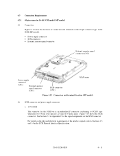
For details on the physical/electrical requirements of connectors and terminals on the SCSI connector. See Section C.2 in the SCSI Physical Interface Specifications. C141-E128-01EN 4 - 11 4.3 Connection Requirements 4.3.1 68 pin connector 16-bit SCSI model (MP model) (1) Connectors Figures 4.13 show the locations of the interface signals, ...
For details on the physical/electrical requirements of connectors and terminals on the SCSI connector. See Section C.2 in the SCSI Physical Interface Specifications. C141-E128-01EN 4 - 11 4.3 Connection Requirements 4.3.1 68 pin connector 16-bit SCSI model (MP model) (1) Connectors Figures 4.13 show the locations of the interface signals, ...

Manual/User Guide
Page 68
... micro program reads the SCSI ID immediately after the power supply to the IDD has been switched on (it is possible to SCSI Logical Interface Specifications. 2. Any load other than the external LED (see Subsection 4.3.5) should not be selected with the CHANGE DEFINITION command. CN1-A4, CN1-A6 ...(reserved) These pins are short-circuited.) A signal for driving the LED is output. 74LS06 or equivalent 150 Ω (IDD) CN1-A2 IMPORTANT This signal is temporarily driven at the GND level when the ...
... micro program reads the SCSI ID immediately after the power supply to the IDD has been switched on (it is possible to SCSI Logical Interface Specifications. 2. Any load other than the external LED (see Subsection 4.3.5) should not be selected with the CHANGE DEFINITION command. CN1-A4, CN1-A6 ...(reserved) These pins are short-circuited.) A signal for driving the LED is output. 74LS06 or equivalent 150 Ω (IDD) CN1-A2 IMPORTANT This signal is temporarily driven at the GND level when the ...

Manual/User Guide
Page 71
.... C141-E128-01EN 4 - 19 See Section C.5 in Appendix C for the SCSI bus is an unshielded SCA-2 connector conforming to Sections 1.3 and 1.4 in SCSI Physical Interface Specifications. For details on the connector. 4.3.2 SCA2 type SCSI model (MC model) (1) Connectors Figure 4.21 shows the locations of MC model (2) SCSI connector and power supply...
.... C141-E128-01EN 4 - 19 See Section C.5 in Appendix C for the SCSI bus is an unshielded SCA-2 connector conforming to Sections 1.3 and 1.4 in SCSI Physical Interface Specifications. For details on the connector. 4.3.2 SCA2 type SCSI model (MC model) (1) Connectors Figure 4.21 shows the locations of MC model (2) SCSI connector and power supply...

Manual/User Guide
Page 73
... ELECTRIC S3 Cable (AWG26 to 36) External Cable socket housing FCN-723J016/2M FUJITSU TAKAMIZAWA operator panel (CN2) Contact FCN-723J-G/AM FUJITSU TAKAMIZAWA S4 Cable (AWG28) SCSI MC connector Connector (CN1) 71780-003 FCI (1) SCSI cable See Section 1.3, "Physical Requirements", and Section 1.4, "Electrical Requirements", in SCSI Physical Interface Specifications. (2) Power cable IDDs must...
... ELECTRIC S3 Cable (AWG26 to 36) External Cable socket housing FCN-723J016/2M FUJITSU TAKAMIZAWA operator panel (CN2) Contact FCN-723J-G/AM FUJITSU TAKAMIZAWA S4 Cable (AWG28) SCSI MC connector Connector (CN1) 71780-003 FCI (1) SCSI cable See Section 1.3, "Physical Requirements", and Section 1.4, "Electrical Requirements", in SCSI Physical Interface Specifications. (2) Power cable IDDs must...
