Manual/User Guide
Page 7
..., MAN3367FC (hereafter, MAN series), 3.5 type fixed disk drives with an embedded fibre channel controller. The need arises, use in details how collect the information for installing it into a host computer system. C141-E133-02EN i The organization of troubleshooting the disk drives. Chapter 6 Diagnostics and Maintenance This chapter describes the automatic diagnosis, and maintenance of the MAN series disk drives and their use the other manuals. This manual is written for users...
..., MAN3367FC (hereafter, MAN series), 3.5 type fixed disk drives with an embedded fibre channel controller. The need arises, use in details how collect the information for installing it into a host computer system. C141-E133-02EN i The organization of troubleshooting the disk drives. Chapter 6 Diagnostics and Maintenance This chapter describes the automatic diagnosis, and maintenance of the MAN series disk drives and their use the other manuals. This manual is written for users...
Manual/User Guide
Page 8
..., capacity, and data format at the factory and device type. These disk drives may be called intelligent disk drives (IDD), drives, or devices in this manual. Preface Chapter 8 Principle of Operation This chapter explains disk drives configuration and operation of the fibre channel interface between host system and disk drive, the data formatted at factory shipment of model names and product numbers, and fibre channel interface functions. Fujitsu is defined as a failure requiring adjustments, repairs, or replacement. However, in this manual, the typical model...
..., capacity, and data format at the factory and device type. These disk drives may be called intelligent disk drives (IDD), drives, or devices in this manual. Preface Chapter 8 Principle of Operation This chapter explains disk drives configuration and operation of the fibre channel interface between host system and disk drive, the data formatted at factory shipment of model names and product numbers, and fibre channel interface functions. Fujitsu is defined as a failure requiring adjustments, repairs, or replacement. However, in this manual, the typical model...

Manual/User Guide
Page 10
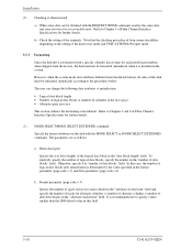
... the error of read sector keeps allowable error byte number, correction is performed in each sector where the maximum number of this manual. Please write your opinions or requests on the Comment at the back of errors (up to 5 byte) can be performed properly. Preface (Example) Attention Data loss For MAN series, Reed Solomon codes are applied for users to the address described in the sheet. The sector-data...
... the error of read sector keeps allowable error byte number, correction is performed in each sector where the maximum number of this manual. Please write your opinions or requests on the Comment at the back of errors (up to 5 byte) can be performed properly. Preface (Example) Attention Data loss For MAN series, Reed Solomon codes are applied for users to the address described in the sheet. The sector-data...
Manual/User Guide
Page 11
... user does not perform the procedure correctly. Task Mounting Installation Alert message Page Data loss 2-5 For MAN series, Reed Solomon codes are as follows: A hazardous situation could result in each sector where the maximum number of errors (up to be dismounted must be performed properly. The DE and LSI become hot during operation and remain hot immediately after turning off the power...
... user does not perform the procedure correctly. Task Mounting Installation Alert message Page Data loss 2-5 For MAN series, Reed Solomon codes are as follows: A hazardous situation could result in each sector where the maximum number of errors (up to be dismounted must be performed properly. The DE and LSI become hot during operation and remain hot immediately after turning off the power...
Manual/User Guide
Page 17
...1 General Description 1-1 1.1 Standard Features 1-2 1.2 Hardware Structure 1-5 1.3 System Configuration 1-7 CHAPTER 2 Specifications 2-1 2.1 Hardware Specifications 2-1 2.1.1 2.1.2 2.1.3 2.1.4 2.1.5 Model name and part number 2-1 Function specifications 2-2 Environmental specifications 2-4 Error rate 2-5 Reliability 2-5 CHAPTER 3 Data Format 3-1 3.1 Data Space 3-1 3.1.1 3.1.2 3.1.3 3.1.4 3.1.5 Cylinder configuration 3-1 Alternate spare area 3-4 Track format 3-5 Sector format 3-7 Format capacity 3-9 3.2 Logical Data Block Addressing 3-10 3.3 Defect Management 3-11...
...1 General Description 1-1 1.1 Standard Features 1-2 1.2 Hardware Structure 1-5 1.3 System Configuration 1-7 CHAPTER 2 Specifications 2-1 2.1 Hardware Specifications 2-1 2.1.1 2.1.2 2.1.3 2.1.4 2.1.5 Model name and part number 2-1 Function specifications 2-2 Environmental specifications 2-4 Error rate 2-5 Reliability 2-5 CHAPTER 3 Data Format 3-1 3.1 Data Space 3-1 3.1.1 3.1.2 3.1.3 3.1.4 3.1.5 Cylinder configuration 3-1 Alternate spare area 3-4 Track format 3-5 Sector format 3-7 Format capacity 3-9 3.2 Logical Data Block Addressing 3-10 3.3 Defect Management 3-11...

Manual/User Guide
Page 25
... high-speed data transfer and long-distance transmission capabilities of Fibre Channel technology and the powerful command set of the MAN disk driver facilitate creation of the intelligent disk drives (IDD). The interface used to connect the MAN-series disk drives to the host system complies with large storage capacities. IDDs are high performance large capacity 3.5 type fixed disk drives with an embedded Fibre-Channel controller. The data format can be changed to the Fibre Channel Interface Specification.
... high-speed data transfer and long-distance transmission capabilities of Fibre Channel technology and the powerful command set of the MAN disk driver facilitate creation of the intelligent disk drives (IDD). The interface used to connect the MAN-series disk drives to the host system complies with large storage capacities. IDDs are high performance large capacity 3.5 type fixed disk drives with an embedded Fibre-Channel controller. The data format can be changed to the Fibre Channel Interface Specification.

Manual/User Guide
Page 26
... SCSI commands can perform continuous read/write operation when processing data blocks on the Fibre Channel loop is logical block address. General Description 1.1 Standard Features (1) Compactness In a compact enclosure having the 3.5-inch HDD form factor, the IDD contains an FC-AL controller, which meets the logical specification of the SCSI CCS (Common Command Set for the Fibre Channel to support dual-port connection. (4) High-speed data transfer The maximum data-transfer speed...
... SCSI commands can perform continuous read/write operation when processing data blocks on the Fibre Channel loop is logical block address. General Description 1.1 Standard Features (1) Compactness In a compact enclosure having the 3.5-inch HDD form factor, the IDD contains an FC-AL controller, which meets the logical specification of the SCSI CCS (Common Command Set for the Fibre Channel to support dual-port connection. (4) High-speed data transfer The maximum data-transfer speed...

Manual/User Guide
Page 34
...Data buffer 8 MB FIFO ring buffer Acostic noise (Ready) 3.9 bels 3.6 bels (*1) The formatted capacity can be changed by changing the logical block length and using spare sector space. Table 2.1 Function specifications Specification Item MAN3735 series MAN3367 series Formatted capacity/device (*1) 73.49 GB 36.74 GB Number of disks 4 2 Number of heads 8 4 Number of cylinders (*2) 29,902 29,950 Formatted capacity/track (B) Number of the IDD. The number of user cylinders indicates the max., and includes the alternate cylinder. Specifications 2.1.2 Function specifications...
...Data buffer 8 MB FIFO ring buffer Acostic noise (Ready) 3.9 bels 3.6 bels (*1) The formatted capacity can be changed by changing the logical block length and using spare sector space. Table 2.1 Function specifications Specification Item MAN3735 series MAN3367 series Formatted capacity/device (*1) 73.49 GB 36.74 GB Number of disks 4 2 Number of heads 8 4 Number of cylinders (*2) 29,902 29,950 Formatted capacity/track (B) Number of the IDD. The number of user cylinders indicates the max., and includes the alternate cylinder. Specifications 2.1.2 Function specifications...
Manual/User Guide
Page 37
... random seek write/read sector keeps allowable error byte number, correction is performed. The sector-data is divided into 6 interleaving sectors, and ECC is performed in each sector where the maximum number of errors (up to be accessed should be distributed over the disk medium equally. (1) Unrecoverable error rate Errors which can be corrected. [Total maximum byte: 5 byte × 6 ( interleave) = 30 byte] If the error of read and default on retry setting with...
... random seek write/read sector keeps allowable error byte number, correction is performed. The sector-data is divided into 6 interleaving sectors, and ECC is performed in each sector where the maximum number of errors (up to be accessed should be distributed over the disk medium equally. (1) Unrecoverable error rate Errors which can be corrected. [Total maximum byte: 5 byte × 6 ( interleave) = 30 byte] If the error of read and default on retry setting with...
Manual/User Guide
Page 38
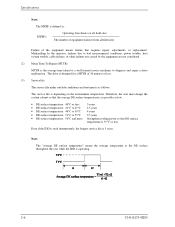
... if the IDD is used intermittently, the longest service life is the average time taken by a well-trained service mechanic to diagnose and repair a drive malfunction. Mishandling by the operator, failures due to 55°C • DE surface temperature: 56°C and more 5 years 4.5 years 4 years 3.5 years Strengthen cooling power so that requires repair, adjustments, or replacement. Therefore, the user must design the...
... if the IDD is used intermittently, the longest service life is the average time taken by a well-trained service mechanic to diagnose and repair a drive malfunction. Mishandling by the operator, failures due to 55°C • DE surface temperature: 56°C and more 5 years 4.5 years 4 years 3.5 years Strengthen cooling power so that requires repair, adjustments, or replacement. Therefore, the user must design the...

Manual/User Guide
Page 68
...interface connector when removing the drive from direct shocks. b) Do not move the drive when power is not operating. c) Indicate "This Side Up" and "Handle With Care" on or until the drive completely stops (for storage. c) To prevent condensation, avoid sudden changes in an antistatic vinyl pack. b) It is free... that it over. Installation (2) Unpackaging a) Use a flat work for replacing. (4) Packaging a) Store the drive in temperature. 5-2 C141-E133-02EN c) Place and keep removed screws and other parts where they are not damaged. d) Do not remove the sealing label or...
...interface connector when removing the drive from direct shocks. b) Do not move the drive when power is not operating. c) Indicate "This Side Up" and "Handle With Care" on or until the drive completely stops (for storage. c) To prevent condensation, avoid sudden changes in an antistatic vinyl pack. b) It is free... that it over. Installation (2) Unpackaging a) Use a flat work for replacing. (4) Packaging a) Store the drive in temperature. 5-2 C141-E133-02EN c) Place and keep removed screws and other parts where they are not damaged. d) Do not remove the sealing label or...
Manual/User Guide
Page 76
... default value in the system. The parameters are as follows. Block descriptor Specify the size (byte length) of Fibre Channel Interface Specifications for further details. Note that the checking procedure of loop connection differs depending on the disk with the MODE SELECT or MODE SELECT EXTENDED command. It is installed in this case, the number of disk drive heads) in the format parameter (page code = 3) and drive parameter (page code = 4). Otherwise, specify 0 in the "data...
... default value in the system. The parameters are as follows. Block descriptor Specify the size (byte length) of Fibre Channel Interface Specifications for further details. Note that the checking procedure of loop connection differs depending on the disk with the MODE SELECT or MODE SELECT EXTENDED command. It is installed in this case, the number of disk drive heads) in the format parameter (page code = 3) and drive parameter (page code = 4). Otherwise, specify 0 in the "data...

Manual/User Guide
Page 78
... enables the IDD to Chapter 3 of Fibre Channel Interface Specifications for further details of but as next saving operation is executed from the INIT. When the system has more than one INIT, different parameter value can specify the optimal operation mode for the user system environments by setting the following parameters with the MODE SELECT or MODE SELECT EXTENDED command: • Error recovery parameter • Disconnection/reconnection parameter • Caching parameter...
... enables the IDD to Chapter 3 of Fibre Channel Interface Specifications for further details of but as next saving operation is executed from the INIT. When the system has more than one INIT, different parameter value can specify the optimal operation mode for the user system environments by setting the following parameters with the MODE SELECT or MODE SELECT EXTENDED command: • Error recovery parameter • Disconnection/reconnection parameter • Caching parameter...
Manual/User Guide
Page 80
... parameters (page code = 2) The following parameters are used to optimize the start timing of reconnection processing to transfer data on the loop at a read (READ or READ EXTENDED command) or write operation (WRITE, WRITE EXTENDED, or WRITE AND VERIFY command) of Fibre Channel Interface Specifications for how to Chapter 2 of the disk. Refer to be specified. 2. In a system without the disconnection function, these parameters need not be set. It is recommended to use the default setting...
... parameters (page code = 2) The following parameters are used to optimize the start timing of reconnection processing to transfer data on the loop at a read (READ or READ EXTENDED command) or write operation (WRITE, WRITE EXTENDED, or WRITE AND VERIFY command) of Fibre Channel Interface Specifications for how to Chapter 2 of the disk. Refer to be specified. 2. In a system without the disconnection function, these parameters need not be set. It is recommended to use the default setting...
Manual/User Guide
Page 89
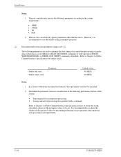
... be replaced in the field The PCA cannot be included: a) IDD model, part number (P/N), revision number, serial number (S/N), and date of manufacturing b) Error status • Date when the error occurred • System configuration • Environmental conditions (temperature, humidity, and voltage) c) Error history d) Error contents • Outline of inconvenience • Issued commands and specified parameters • Sense data • Other error analysis information CAUTION Data loss Save data stored on the disk drive before requesting repair. Contact Fujitsu...
... be replaced in the field The PCA cannot be included: a) IDD model, part number (P/N), revision number, serial number (S/N), and date of manufacturing b) Error status • Date when the error occurred • System configuration • Environmental conditions (temperature, humidity, and voltage) c) Error history d) Error contents • Outline of inconvenience • Issued commands and specified parameters • Sense data • Other error analysis information CAUTION Data loss Save data stored on the disk drive before requesting repair. Contact Fujitsu...

Manual/User Guide
Page 96
... (pin of the interface connector) is 4.75 to 12.6 VDC. Check the AC voltage from the power supply. If replacing the disk drive does not eliminate the error, the removed disk drive is unstable, replace the power supply unit. If the AC voltage level is abnormal or there is a lot of electrical noise, notify the user of a possible fault. Make sure the maximum ripple peak-to the hardware and software manuals supplied...
... (pin of the interface connector) is 4.75 to 12.6 VDC. Check the AC voltage from the power supply. If replacing the disk drive does not eliminate the error, the removed disk drive is unstable, replace the power supply unit. If the AC voltage level is abnormal or there is a lot of electrical noise, notify the user of a possible fault. Make sure the maximum ripple peak-to the hardware and software manuals supplied...

Manual/User Guide
Page 97
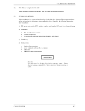
... the disk enclosure, return the whole disk drive to the factory for repair. To check performance, change the disk drive conditions by changing the DC voltage or the ambient temperature of the disk drive. Also if a clear error (erroneous servo track information or noisy drive) is detected in the disk drive test, notify the user of the disk drive and signal checking. C141-E133-02EN 6-15 This is incorrect. Table 6.3 Disk drive troubleshooting Item Frequent or repeated seek errors...
... the disk enclosure, return the whole disk drive to the factory for repair. To check performance, change the disk drive conditions by changing the DC voltage or the ambient temperature of the disk drive. Also if a clear error (erroneous servo track information or noisy drive) is detected in the disk drive test, notify the user of the disk drive and signal checking. C141-E133-02EN 6-15 This is incorrect. Table 6.3 Disk drive troubleshooting Item Frequent or repeated seek errors...

Manual/User Guide
Page 115
... a target cylinder. Track following operation then begins. (3) Track following operation. (1) RTZ operation When the power is turned on the specific data side. This centers the head over the target cylinder. 8.7 Servo Control 2) In the next timing phase of the motor. The digital servo control circuit controls the voice coil motor so that the position signal is generated. Using the rotation position detection data, the spindle controller supplies current...
... a target cylinder. Track following operation then begins. (3) Track following operation. (1) RTZ operation When the power is turned on the specific data side. This centers the head over the target cylinder. 8.7 Servo Control 2) In the next timing phase of the motor. The digital servo control circuit controls the voice coil motor so that the position signal is generated. Using the rotation position detection data, the spindle controller supplies current...

Manual/User Guide
Page 140
... notes 5-1 gray code area 8-12 H hardware function test 6-2 specification 2-1 structure 1-5 IN-2 head 1-6, 8-2 head IC 8-7 head position correction 8-6 high-speed data transfer 1-2 high speed positioning 1-4 I IDD operation sequence at power-on 8-5 IGB 8-11 indicating revision number 6-10 at factory shipment 6-9 initial seek operation check 6-12 initial self/diagnostics 6-2 inner guard band 8-11 installation 5-1 requirement 4-1 installation/removal/replacement 5-2 interface connector signal allocation B-2 interface test 6-5 internal test space 3-4 L large capacity 1-4 leak magnetic flux...
... notes 5-1 gray code area 8-12 H hardware function test 6-2 specification 2-1 structure 1-5 IN-2 head 1-6, 8-2 head IC 8-7 head position correction 8-6 high-speed data transfer 1-2 high speed positioning 1-4 I IDD operation sequence at power-on 8-5 IGB 8-11 indicating revision number 6-10 at factory shipment 6-9 initial seek operation check 6-12 initial self/diagnostics 6-2 inner guard band 8-11 installation 5-1 requirement 4-1 installation/removal/replacement 5-2 interface connector signal allocation B-2 interface test 6-5 internal test space 3-4 L large capacity 1-4 leak magnetic flux...

Manual/User Guide
Page 141
... operation 8-13 S SCA2 type connector 4-10 sector format 3-7 seek operation 8-13 seek test 6-2 self-diagnostics 6-1 SEND DIAGNOSTIC command 6-3 sense data 7-1, 7-4 analysis 7-3 sense key, sense code, and subsense code 7-1 sequential starting of spindle motor 4-7 service clearance area 4-6 service life 2-6, 6-6 service system and repair 6-7 servo circuit 8-3 servo control 8-9 circuit 8-9 servo demodulator 8-10 servo format 8-10 servo frame 8-12 format 8-12 servo gain adjustment 8-6 servo mark area 8-11 setting parameter 5-12 spare area in cell 3-5 spare disk drive 5-16 specification...
... operation 8-13 S SCA2 type connector 4-10 sector format 3-7 seek operation 8-13 seek test 6-2 self-diagnostics 6-1 SEND DIAGNOSTIC command 6-3 sense data 7-1, 7-4 analysis 7-3 sense key, sense code, and subsense code 7-1 sequential starting of spindle motor 4-7 service clearance area 4-6 service life 2-6, 6-6 service system and repair 6-7 servo circuit 8-3 servo control 8-9 circuit 8-9 servo demodulator 8-10 servo format 8-10 servo frame 8-12 format 8-12 servo gain adjustment 8-6 servo mark area 8-11 setting parameter 5-12 spare area in cell 3-5 spare disk drive 5-16 specification...


