
Manual/User Guide
Page 36
... block length (Logical data length=Physical data length) (*2) 512 to 528 bytes (Fixed length) Ο : Provided × : Not provided (*1) Single-Ended and LVD detect the driver mode by Diffsence signal and automatically change. (*2) Refer to #15 (Jumper selection) #0 fixed Data transfer 8-bit SCSI (Single-Ended type) (Synchronous (LVD type) mode) 16...
... block length (Logical data length=Physical data length) (*2) 512 to 528 bytes (Fixed length) Ο : Provided × : Not provided (*1) Single-Ended and LVD detect the driver mode by Diffsence signal and automatically change. (*2) Refer to #15 (Jumper selection) #0 fixed Data transfer 8-bit SCSI (Single-Ended type) (Synchronous (LVD type) mode) 16...

Manual/User Guide
Page 59
d) Impact caused by the electric driver must be secured with 0.59N·m (6kgf·cm). e) Must be within the device specifications. Mount the IDD with an embossed structure, or the like. b) ...
d) Impact caused by the electric driver must be secured with 0.59N·m (6kgf·cm). e) Must be within the device specifications. Mount the IDD with an embossed structure, or the like. b) ...

Manual/User Guide
Page 61
Table 4.1 Surface temperature check point No. Confirm the cooling effect by measuring temperature of DE cover 2 Read channel LSI 3 VCM/SPM Driver 4 HDC Criteria 55°C 83°C 92°C 85°C MAJ3364 Series 3 2 1 MAJ3182, MAJ3091 Series 1 4 3 2 MAH Series 1 4 4 3 2 Figure 4.8 Surface temperature measurement points 4 - 8 C141-E103-...that the DE surface temperature does not exceed 55°C. • Cool the PCA side especially with ambient temperature measured 3 cm from the disk drive. (4) Environmental temperature Temperature condition at installed in Table 4.1.
Table 4.1 Surface temperature check point No. Confirm the cooling effect by measuring temperature of DE cover 2 Read channel LSI 3 VCM/SPM Driver 4 HDC Criteria 55°C 83°C 92°C 85°C MAJ3364 Series 3 2 1 MAJ3182, MAJ3091 Series 1 4 3 2 MAH Series 1 4 4 3 2 Figure 4.8 Surface temperature measurement points 4 - 8 C141-E103-...that the DE surface temperature does not exceed 55°C. • Cool the PCA side especially with ambient temperature measured 3 cm from the disk drive. (4) Environmental temperature Temperature condition at installed in Table 4.1.
Manual/User Guide
Page 91
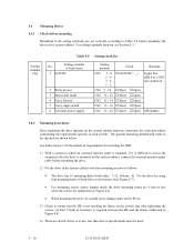
...both sides: 3 ×2, bottom: 4). Fix the drive by using four mounting holes of clearance is required between the DE and the frame. (Indicated in Figure 4.6) 4) When an electric driver is mounted on the system side after the drive is in use, less than device specifications must be ...checked are shown below. 5.4 Mounting Drives 5.4.1 Check before mounting Reconfirm if the setting terminals are set correctly ...
...both sides: 3 ×2, bottom: 4). Fix the drive by using four mounting holes of clearance is required between the DE and the frame. (Indicated in Figure 4.6) 4) When an electric driver is mounted on the system side after the drive is in use, less than device specifications must be ...checked are shown below. 5.4 Mounting Drives 5.4.1 Check before mounting Reconfirm if the setting terminals are set correctly ...

Manual/User Guide
Page 129
...by the control circuit. Also, when an instruction that were measured in each device. Self-calibration measures and records external forces on each drive must be measured and stored in flash memory. Measurement is generated. 8 - 6 C141-E103-02EN To adjust precisely, the offset value... to the circuit. To compensate, the read head must be centered when writing. The head IC has a preamplifier and a write current driver, and has a write error detection function. This provides stable seek operation. (2) Servo gain adjustment The servo control circuit gives stable operation when...
...by the control circuit. Also, when an instruction that were measured in each device. Self-calibration measures and records external forces on each drive must be measured and stored in flash memory. Measurement is generated. 8 - 6 C141-E103-02EN To adjust precisely, the offset value... to the circuit. To compensate, the read head must be centered when writing. The head IC has a preamplifier and a write current driver, and has a write error detection function. This provides stable seek operation. (2) Servo gain adjustment The servo control circuit gives stable operation when...

Manual/User Guide
Page 134
... 8.5 shows zone format. 1) Dead space The dead space is at the innermost position of a disk. (3) SPM/VCM driver The power amp drive signal output by detecting the counter electro-motive voltage and a power MOSFET which drives the spindle motor. (MAH series, MAJ3182 series and MAJ3091 series contain a power transistor inside the SPM/VCM... processor) is converted to a current for MAJ series per one revolution. This consists of 108 servo frames for MAH series, or 84 servo frames for driving the VCM.
... 8.5 shows zone format. 1) Dead space The dead space is at the innermost position of a disk. (3) SPM/VCM driver The power amp drive signal output by detecting the counter electro-motive voltage and a power MOSFET which drives the spindle motor. (MAH series, MAJ3182 series and MAJ3091 series contain a power transistor inside the SPM/VCM... processor) is converted to a current for MAJ series per one revolution. This consists of 108 servo frames for MAH series, or 84 servo frames for driving the VCM.


