Manual/User Guide
Page 5
... (SCSI) (ANSI) American National Standard for American National Information Technology-SCSI-3 Block Standards Institute Commands (SBC) (ANSI) WORKING DRAFT Information American National technology SCSI-3 Architecture Model Standards Institute (SAM) (ANSI) WORKING DRAFT Information technology SCSI Parallel Interface-3 (SPI-3) American National Standards Institute (ANSI) All Right Reserved, Copyright © 2000...
... (SCSI) (ANSI) American National Standard for American National Information Technology-SCSI-3 Block Standards Institute Commands (SBC) (ANSI) WORKING DRAFT Information American National technology SCSI-3 Architecture Model Standards Institute (SAM) (ANSI) WORKING DRAFT Information technology SCSI Parallel Interface-3 (SPI-3) American National Standards Institute (ANSI) All Right Reserved, Copyright © 2000...
Manual/User Guide
Page 7
...equipment, data, and/or other property may occur if the user does not perform the procedure correctly. Indicates vi C141-E103-02EN The model numbers have a suffix that either minor or moderate personal injury may occur if the user does not pay attention or perform the procedure ...and connectors, a list of setting items, the signal assignments of interface connectors, lists of the SCSI interface between host system and disk drive, the data formatted at the factory and device type. CONVENTIONS This manual uses the following conventions for alerts to prevent physical or property damages...
...equipment, data, and/or other property may occur if the user does not perform the procedure correctly. Indicates vi C141-E103-02EN The model numbers have a suffix that either minor or moderate personal injury may occur if the user does not pay attention or perform the procedure ...and connectors, a list of setting items, the signal assignments of interface connectors, lists of the SCSI interface between host system and disk drive, the data formatted at the factory and device type. CONVENTIONS This manual uses the following conventions for alerts to prevent physical or property damages...
Manual/User Guide
Page 8
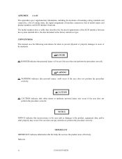
...010" DISCLAIMER Failure of the MAH series and MAJ series intelligent disk drive is not responsible for connecting the three device types or host system and the disk drives (Note 1). Fujitsu is defined as it is. Decimal number: Indicates as a failure... 10,025min-1 (10,025rpm) Note 2: Type model name Type model name Model name MAH3182 MAH3182MC, MAH3182MP MAH3091 MAH3091MC, MAH3091MP MAJ3364 MAJ3364MC, MAJ3364MP MAJ3182 MAJ3182MC, MAJ3182MP MAJ3091 MAJ3091MC, MAJ3091MP C141-E103-02EN vii Hand Disk Drive Type AH: Number of rotations 7,200min-1 (7,200rpm...
...010" DISCLAIMER Failure of the MAH series and MAJ series intelligent disk drive is not responsible for connecting the three device types or host system and the disk drives (Note 1). Fujitsu is defined as it is. Decimal number: Indicates as a failure... 10,025min-1 (10,025rpm) Note 2: Type model name Type model name Model name MAH3182 MAH3182MC, MAH3182MP MAH3091 MAH3091MC, MAH3091MP MAJ3364 MAJ3364MC, MAJ3364MP MAJ3182 MAJ3182MC, MAJ3182MP MAJ3091 MAJ3091MC, MAJ3091MP C141-E103-02EN vii Hand Disk Drive Type AH: Number of rotations 7,200min-1 (7,200rpm...
Manual/User Guide
Page 12
CONTENTS page CHAPTER 1 GENERAL DESCRIPTION 1-1 1.1 Standard Features ...1-2 1.2 Hardware Structure...1-5 1.3 System Configuration ...1-9 CHAPTER 2 SPECIFICATIONS 2-1 2.1 Hardware Specifications...2-1 2.1.1 Model name and part number 2-1 2.1.2 Function specifications...2-2 2.1.3 Environmental specifications 2-4 2.1.4 Error rate ...2-5 2.1.5 Reliability...2-5 2.2 SCSI Function Specifications 2-7 CHAPTER 3 DATA FORMAT 3-1 3.1 Data Space...3-1 3.1.1 Cylinder configuration...3-1 3.1.2 Alternate spare area...3-5 3.1.3 Track ...
CONTENTS page CHAPTER 1 GENERAL DESCRIPTION 1-1 1.1 Standard Features ...1-2 1.2 Hardware Structure...1-5 1.3 System Configuration ...1-9 CHAPTER 2 SPECIFICATIONS 2-1 2.1 Hardware Specifications...2-1 2.1.1 Model name and part number 2-1 2.1.2 Function specifications...2-2 2.1.3 Environmental specifications 2-4 2.1.4 Error rate ...2-5 2.1.5 Reliability...2-5 2.2 SCSI Function Specifications 2-7 CHAPTER 3 DATA FORMAT 3-1 3.1 Data Space...3-1 3.1.1 Cylinder configuration...3-1 3.1.2 Alternate spare area...3-5 3.1.3 Track ...
Manual/User Guide
Page 13
...model (MP model 4-14 SCA2 type SCSI model (MC model 4-22 Cable connector requirements 4-26 External operator panel ...4-27 CHAPTER 5 INSTALLATION 5-1 5.1 Notes on Handling Drives ...5-1 5.2 Connections...5-3 5.3 Setting Terminals ...5-5 5.3.1 SCSI ID setting...5-6 5.3.2 Each mode setting ...5-7 5.3.3 Mode settings ...5-9 5.4 Mounting Drives...5.6.2 Checking SCSI connection...5-13 5.6.3 Formatting ...5-16 5.6.4 Setting parameters ...5-18 5.7 Dismounting Drives...5-22 5.8 Spare Disk Drive ...5-22 CHAPTER 6 DIAGNOSTICS AND MAINTENANCE 6-1 6.1 Diagnostics ...6-1 6.1.1 Self-diagnostics ...6-1 ...
...model (MP model 4-14 SCA2 type SCSI model (MC model 4-22 Cable connector requirements 4-26 External operator panel ...4-27 CHAPTER 5 INSTALLATION 5-1 5.1 Notes on Handling Drives ...5-1 5.2 Connections...5-3 5.3 Setting Terminals ...5-5 5.3.1 SCSI ID setting...5-6 5.3.2 Each mode setting ...5-7 5.3.3 Mode settings ...5-9 5.4 Mounting Drives...5.6.2 Checking SCSI connection...5-13 5.6.3 Formatting ...5-16 5.6.4 Setting parameters ...5-18 5.7 Dismounting Drives...5-22 5.8 Spare Disk Drive ...5-22 CHAPTER 6 DIAGNOSTICS AND MAINTENANCE 6-1 6.1 Diagnostics ...6-1 6.1.1 Self-diagnostics ...6-1 ...
Manual/User Guide
Page 15
... AND SETTING TERMINALS A-1 A.1 Locations of Connectors and Setting Terminals (MAH series MC model A-2 A.2 Locations of Connectors and Setting Terminals (MAH series MP model A-3 A.3 Locations of Connectors and Setting Terminals (MAJ series MC model A-4 A.4 Locations of Connectors and Setting Terminals (MAJ series MP model A-5 APPENDIX B SETTING TERMINALS B-1 B.1 Setting Terminals ...B-2 APPENDIX C CONNECTOR SIGNAL ALLOCATION C-1 C.1 SCSI Connector...
... AND SETTING TERMINALS A-1 A.1 Locations of Connectors and Setting Terminals (MAH series MC model A-2 A.2 Locations of Connectors and Setting Terminals (MAH series MP model A-3 A.3 Locations of Connectors and Setting Terminals (MAJ series MC model A-4 A.4 Locations of Connectors and Setting Terminals (MAJ series MP model A-5 APPENDIX B SETTING TERMINALS B-1 B.1 Setting Terminals ...B-2 APPENDIX C CONNECTOR SIGNAL ALLOCATION C-1 C.1 SCSI Connector...
Manual/User Guide
Page 16
...command 3-14 3.8 Alternate block allocation by REASSIGN BLOCKS command 3-15 4.1 External dimensions (MAH series MC model 4-2 4.2 External dimensions (MAH series MP model 4-3 4.3 External dimensions (MAJ series MC model 4-4 4.4 External dimensions (MAJ series MP model 4-5 4.5 IDD directions...4-6 4.6 Mounting frame structure ...4-7 4.7 Limitation of side-mounting 4-7 4.8 Surface temperature ... sequence (3)...4-12 4.15 AC noise filter (recommended 4-13 4.16 Connectors and terminals location (MP model 4-14 4.17 16-bit SCSI interface connector 4-15 4.18 Power supply connector (16-bit SCSI...
...command 3-14 3.8 Alternate block allocation by REASSIGN BLOCKS command 3-15 4.1 External dimensions (MAH series MC model 4-2 4.2 External dimensions (MAH series MP model 4-3 4.3 External dimensions (MAJ series MC model 4-4 4.4 External dimensions (MAJ series MP model 4-5 4.5 IDD directions...4-6 4.6 Mounting frame structure ...4-7 4.7 Limitation of side-mounting 4-7 4.8 Surface temperature ... sequence (3)...4-12 4.15 AC noise filter (recommended 4-13 4.16 Connectors and terminals location (MP model 4-14 4.17 16-bit SCSI interface connector 4-15 4.18 Power supply connector (16-bit SCSI...
Manual/User Guide
Page 17
...input 4-18 4.22 Output signal for external LED 4-20 4.23 SCSI cables connection ...4-21 4.24 Connectors and terminals location of MC model 4-22 4.25 SCA2 type SCSI connector 4-23 4.26 External operator panel connector (CN2 4-24 4.27 16-bit SCSI ID external ... servo track...8-12 8.6 Servo frame ...8-13 A.1 Locations of connectors and setting terminals (MAH series MC model A-2 A.2 Locations of connectors and setting terminals (MAH series MP model A-3 A.3 Locations of connectors and setting terminals (MAJ series MC model A-4 A.4 Locations of connectors and setting terminals (MAJ series MP...
...input 4-18 4.22 Output signal for external LED 4-20 4.23 SCSI cables connection ...4-21 4.24 Connectors and terminals location of MC model 4-22 4.25 SCA2 type SCSI connector 4-23 4.26 External operator panel connector (CN2 4-24 4.27 16-bit SCSI ID external ... servo track...8-12 8.6 Servo frame ...8-13 A.1 Locations of connectors and setting terminals (MAH series MC model A-2 A.2 Locations of connectors and setting terminals (MAH series MP model A-3 A.3 Locations of connectors and setting terminals (MAJ series MC model A-4 A.4 Locations of connectors and setting terminals (MAJ series MP...
Manual/User Guide
Page 18
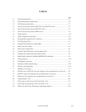
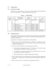
...CN2 5-9 5.7 Default mode settings (by CHANGE DEFINITION command 5-9 5.8 Setting check list ...5-10 6.1 Self-diagnostic functions ...6-1 6.2 System-level field troubleshooting 6-14 6.3 Disk drive troubleshooting ...6-15 7.1 Definition of sense data ...7-3 8.1 MAJ3364 series, MAJ3182 series date frequency and recording density in each zone ........8-8 8.2 MAJ3091 series write frequency and recording ...connector (SCA2 type LVD 16-bit SCSI): CN1 C-2 C.2 SCSI connector (68 pin type LVD 16-bit SCSI): CN1 C-3 D.1 MAH series, MAJ series model names and product numbers D-2 C141-E103-02EN xvii
...CN2 5-9 5.7 Default mode settings (by CHANGE DEFINITION command 5-9 5.8 Setting check list ...5-10 6.1 Self-diagnostic functions ...6-1 6.2 System-level field troubleshooting 6-14 6.3 Disk drive troubleshooting ...6-15 7.1 Definition of sense data ...7-3 8.1 MAJ3364 series, MAJ3182 series date frequency and recording density in each zone ........8-8 8.2 MAJ3091 series write frequency and recording ...connector (SCA2 type LVD 16-bit SCSI): CN1 C-2 C.2 SCSI connector (68 pin type LVD 16-bit SCSI): CN1 C-3 D.1 MAH series, MAJ series model names and product numbers D-2 C141-E103-02EN xvii
Manual/User Guide
Page 21
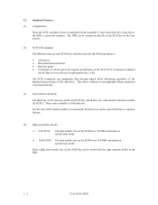
... SCSI commands can manipulate data through logical block addressing regardless of the physical characteristics of the disk drive. Such a high data transfer rate on the same SCSI bus is extremely compact. For the ultra SCSI model, number of system functions. (3) 8-bit SCSI/16-bit SCSI The IDD has 16-bit data bus... large capacity buffer in the IDD. 1 - 2 C141-E103-02EN 1.1 Standard Features (1) Compactness Since the SCSI controller circuit is embedded in the standard 3.5 type fixed disk drive form factor, the IDD is varied as 8-bit data bus.
... SCSI commands can manipulate data through logical block addressing regardless of the physical characteristics of the disk drive. Such a high data transfer rate on the same SCSI bus is extremely compact. For the ultra SCSI model, number of system functions. (3) 8-bit SCSI/16-bit SCSI The IDD has 16-bit data bus... large capacity buffer in the IDD. 1 - 2 C141-E103-02EN 1.1 Standard Features (1) Compactness Since the SCSI controller circuit is embedded in the standard 3.5 type fixed disk drive form factor, the IDD is varied as 8-bit data bus.
Manual/User Guide
Page 26
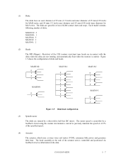
... and positioned via feedback of the CSS (contact start/stop) type heads are not rotating, and automatically float when the rotation is controlled by a direct-drive hall-less DC motor. Resistive) of servo information in contact with the disks when the disks are in the data. C141-E103-02EN 1 - 7 ... series. The motor speed is started. (1) Disks The disks have an outer diameter of 95 mm (3.74 inch) and inner diameter of disks. Each model contains following number of 25 mm (0.98 inch) for MAH series, and 84 mm (3.3 inch) outer diameter and 25 mm (0.98 inch) inner diameter...
... and positioned via feedback of the CSS (contact start/stop) type heads are not rotating, and automatically float when the rotation is controlled by a direct-drive hall-less DC motor. Resistive) of servo information in contact with the disks when the disks are in the data. C141-E103-02EN 1 - 7 ... series. The motor speed is started. (1) Disks The disks have an outer diameter of 95 mm (3.74 inch) and inner diameter of disks. Each model contains following number of 25 mm (0.98 inch) for MAH series, and 84 mm (3.3 inch) outer diameter and 25 mm (0.98 inch) inner diameter...

Manual/User Guide
Page 30
CHAPTER 2 SPECIFICATIONS 2.1 Hardware Specifications 2.2 SCSI Function Specifications This chapter describes specifications of the IDD and the functional specifications of the SCSI. 2.1 Hardware Specifications 2.1.1 Model name and part number Each model has a different data format and front panel type when shipped. (See Appendix D for the model name (type) and product number.) The data format can be changed by reinitializing with the user's system. C141-E103-02EN 2 - 1
CHAPTER 2 SPECIFICATIONS 2.1 Hardware Specifications 2.2 SCSI Function Specifications This chapter describes specifications of the IDD and the functional specifications of the SCSI. 2.1 Hardware Specifications 2.1.1 Model name and part number Each model has a different data format and front panel type when shipped. (See Appendix D for the model name (type) and product number.) The data format can be changed by reinitializing with the user's system. C141-E103-02EN 2 - 1

Manual/User Guide
Page 47
... data block length and the default spare area are specified with the parameter in the alternate cylinders. 3 - 10 C141-E103-02EN Table 3.4 Format capacity Model Data heads Data block length MAH3182 series 4 MAH3091 series 2 MAJ3364 series 10 512 MAJ3182 series 5 MAJ3091 series 3 User blocks 35,701,260 17,850...,264 71,390,320 35,694,904 17,847,486 Format capacity (GB) 18.28 9.14 36.55 18.28 9.14 Note: Total number of spare sectors is calculated by a READ CAPACITY, MODE SENSE, or MODE SENSE EXTENDED command ...
... data block length and the default spare area are specified with the parameter in the alternate cylinders. 3 - 10 C141-E103-02EN Table 3.4 Format capacity Model Data heads Data block length MAH3182 series 4 MAH3091 series 2 MAJ3364 series 10 512 MAJ3182 series 5 MAJ3091 series 3 User blocks 35,701,260 17,850...,264 71,390,320 35,694,904 17,847,486 Format capacity (GB) 18.28 9.14 36.55 18.28 9.14 Note: Total number of spare sectors is calculated by a READ CAPACITY, MODE SENSE, or MODE SENSE EXTENDED command ...

Manual/User Guide
Page 67
... Figures 4.16 show the locations of connectors and terminals on the 68 pin connector type 16-bit SCSI (MP) model. • Power supply connector • SCSI connector • External operator panel connector External operator panel connector (CN2) Power supply connector (CN1) External operator panel connector (... operator panel connector (CN2) Power supply connector (CN1) External operator panel connector (CN1) SCSI connector (CN1) MAJ series Figure 4.16 Connectors and terminals location (MP model) 4 - 14 C141-E103-02EN
... Figures 4.16 show the locations of connectors and terminals on the 68 pin connector type 16-bit SCSI (MP) model. • Power supply connector • SCSI connector • External operator panel connector External operator panel connector (CN2) Power supply connector (CN1) External operator panel connector (... operator panel connector (CN2) Power supply connector (CN1) External operator panel connector (CN1) SCSI connector (CN1) MAJ series Figure 4.16 Connectors and terminals location (MP model) 4 - 14 C141-E103-02EN

Manual/User Guide
Page 68
...-bit SCSI The connector for the signal assignments on the physical/electrical requirements of DC power supply. Figure 4.18 Power supply connector (16-bit SCSI model) C141-E103-02EN 4 - 15 Figure 4.17 shows the SCSI connector.
...-bit SCSI The connector for the signal assignments on the physical/electrical requirements of DC power supply. Figure 4.18 Power supply connector (16-bit SCSI model) C141-E103-02EN 4 - 15 Figure 4.17 shows the SCSI connector.

Manual/User Guide
Page 75
4.3.2 SCA2 type SCSI model (MC model) (1) Connectors Figure 4.24 shows the locations of MC model 4 - 22 C141-E103-02EN SCSI connector (including power supply connector) External operator panel connector (CN2) SCSI connector (CN1) External operator panel connector (CN2) SCSI connector (CN1) Figure 4.24 Connectors and terminals location of connectors and terminals on the SCA2 type SCSI model.
4.3.2 SCA2 type SCSI model (MC model) (1) Connectors Figure 4.24 shows the locations of MC model 4 - 22 C141-E103-02EN SCSI connector (including power supply connector) External operator panel connector (CN2) SCSI connector (CN1) External operator panel connector (CN2) SCSI connector (CN1) Figure 4.24 Connectors and terminals location of connectors and terminals on the SCA2 type SCSI model.

Manual/User Guide
Page 79
...-723J016/2M Contact FCN-723J-G/AM Cable AWG28 MC SCSI connector Connector 787311-1 (CN1) Manufacturer AMP - AMP AMP Fujitsu Limited Fujitsu Limited Fujitsu Limited Fujitsu Limited AMP Reference (Figures 4.25 and 4.30) S1 S2 S3 S4 (1) SCSI cable See Section 1.3, "Physical ...Requirements", and Section 1.4, "Electrical Requirements", in the system, it is provided with the IDD. Table 4.2 Recommended components for connection Applicable model...
...-723J016/2M Contact FCN-723J-G/AM Cable AWG28 MC SCSI connector Connector 787311-1 (CN1) Manufacturer AMP - AMP AMP Fujitsu Limited Fujitsu Limited Fujitsu Limited Fujitsu Limited AMP Reference (Figures 4.25 and 4.30) S1 S2 S3 S4 (1) SCSI cable See Section 1.3, "Physical ...Requirements", and Section 1.4, "Electrical Requirements", in the system, it is provided with the IDD. Table 4.2 Recommended components for connection Applicable model...

Manual/User Guide
Page 87
Force Single Ended: LVD mode Force Narrow: 16bit-SCSI Spin-up mode Write protect: enabled SCSI ID #15 (MP model) # 0 (MC model) 2 4 6 8 10 12 14 16 1 3 5 7 9 11 13 15 MC model Figure 5.3 Setting terminals (CN2) 5.3.1 SCSI ID setting Table 5.1 shows the SCSI ID setting. IMPORTANT When the SCSI ID is set using the ...external operator panel connector CN1, all pins listed in Table 5.1 should be open. MP model 2 4 6 8 10 12 14 16 18 20 22 24 1 3 5 7 9 11 13 15 17 19 21 23 Terminal power supply: Supply (LED signal) (IDD Reset signal) N.C. ...
Force Single Ended: LVD mode Force Narrow: 16bit-SCSI Spin-up mode Write protect: enabled SCSI ID #15 (MP model) # 0 (MC model) 2 4 6 8 10 12 14 16 1 3 5 7 9 11 13 15 MC model Figure 5.3 Setting terminals (CN2) 5.3.1 SCSI ID setting Table 5.1 shows the SCSI ID setting. IMPORTANT When the SCSI ID is set using the ...external operator panel connector CN1, all pins listed in Table 5.1 should be open. MP model 2 4 6 8 10 12 14 16 18 20 22 24 1 3 5 7 9 11 13 15 17 19 21 23 Terminal power supply: Supply (LED signal) (IDD Reset signal) N.C. ...

Manual/User Guide
Page 88
...factory shipment 1-2 Open Short Open Short Open Short Open Short Open Short Open Short Open Short Open Short IMPORTANT 1. For information on MP model, refer to the SCSI terminal resistance power source (TERMPOW). Table 5.2 Setting SCSI terminal power supply (MP) Supply on/off Supply on... to Table 5.2 for controlling the supply of power from IDD Supply off of SCSI terminating resistor power from the drive to Figures 5.2 and 5.3. However, this setting may not be used with MC model. Table 5.1 SCSI ID setting (CN2) SCSI ID CN2 7-8 5-6 3-4 0 Open Open Open 1 Open Open Open...
...factory shipment 1-2 Open Short Open Short Open Short Open Short Open Short Open Short Open Short Open Short IMPORTANT 1. For information on MP model, refer to the SCSI terminal resistance power source (TERMPOW). Table 5.2 Setting SCSI terminal power supply (MP) Supply on/off Supply on... to Table 5.2 for controlling the supply of power from IDD Supply off of SCSI terminating resistor power from the drive to Figures 5.2 and 5.3. However, this setting may not be used with MC model. Table 5.1 SCSI ID setting (CN2) SCSI ID CN2 7-8 5-6 3-4 0 Open Open Open 1 Open Open Open...
Manual/User Guide
Page 91
... is mounted, if it is difficult to 15 PI) not connected MP models 5.4.2 Mounting procedures Since mounting the drive depends on the system cabinet, connect the external operator panel cable before mounting the drive. 2) Fix the drive in the system cabinet with four mounting screws as follows: • The... each system. At least 2.5mm of both sides: 3 ×2, bottom: 4). For setting terminals location, see Figure 4.6). • When mounting the drive, be careful not to damage parts on the PCAs. 3) Check to ensure that the DE is in use, less than device specifications must be checked...
... is mounted, if it is difficult to 15 PI) not connected MP models 5.4.2 Mounting procedures Since mounting the drive depends on the system cabinet, connect the external operator panel cable before mounting the drive. 2) Fix the drive in the system cabinet with four mounting screws as follows: • The... each system. At least 2.5mm of both sides: 3 ×2, bottom: 4). For setting terminals location, see Figure 4.6). • When mounting the drive, be careful not to damage parts on the PCAs. 3) Check to ensure that the DE is in use, less than device specifications must be checked...

