
Manual/User Guide
Page 2
Edition 01 02 REVISION RECORD Date published Revised contents Feb., 2000 Dec., 2000 As evaluation result, corrections have been added. All Rights Reserved. Copyright 2000 FUJITSU LIMITED C141-E103-02EN i Specification No.: C141-E103-**EN The contents of this manual is subject to change without prior notice.
Edition 01 02 REVISION RECORD Date published Revised contents Feb., 2000 Dec., 2000 As evaluation result, corrections have been added. All Rights Reserved. Copyright 2000 FUJITSU LIMITED C141-E103-02EN i Specification No.: C141-E103-**EN The contents of this manual is subject to change without prior notice.
Manual/User Guide
Page 5
Related Standards Specifications and functions of the Small Computer System Interface (SCSI) American National Standards Institute (ANSI) WORKING DRAFT Information Technology SCSI-3 Parallel Interface American National Standards Institute (...-3 Architecture Model Standards Institute (SAM) (ANSI) WORKING DRAFT Information technology SCSI Parallel Interface-3 (SPI-3) American National Standards Institute (ANSI) All Right Reserved, Copyright © 2000 Fujitsu Limited iv C141-E103-02EN Standard (Text) No.
Related Standards Specifications and functions of the Small Computer System Interface (SCSI) American National Standards Institute (ANSI) WORKING DRAFT Information Technology SCSI-3 Parallel Interface American National Standards Institute (...-3 Architecture Model Standards Institute (SAM) (ANSI) WORKING DRAFT Information technology SCSI Parallel Interface-3 (SPI-3) American National Standards Institute (ANSI) All Right Reserved, Copyright © 2000 Fujitsu Limited iv C141-E103-02EN Standard (Text) No.
Manual/User Guide
Page 6
... setting device number and operation modes, mounting the disk drive, connecting the cables, and confirming drive operation. Chapter 8 PRINCIPLE OF OPERATION This chapter explains disk drives configuration and operation of MAH series and MAJ series disk drive. Chapter 2 SPECIFICATIONS This chapter gives detailed specifications of fixed disk drives and their standard features, hardware, and system configuration. This...
... setting device number and operation modes, mounting the disk drive, connecting the cables, and confirming drive operation. Chapter 8 PRINCIPLE OF OPERATION This chapter explains disk drives configuration and operation of MAH series and MAJ series disk drive. Chapter 2 SPECIFICATIONS This chapter gives detailed specifications of fixed disk drives and their standard features, hardware, and system configuration. This...
Manual/User Guide
Page 11
Data Format 4. Installation Requirements 5. Installation 6. SCSI Bus 2. Sense Data and error Recovery Procedure 5. SCSI Bus Error Recovery Processing 1. Specifications 3. Command Processing 2. Disk Medium Management x C141-E103-02EN Error Analysis 8. Data Buffer Management 3. General Description 2. SCSI Message 3. Command Specification 4. MANUAL ORGANIZATION PRODUCT/ MAINTENANCE MANUAL (This manual) SCSI Physical Interface Specifications SCSI Logical Interface Specifications 1. Diagnostics and Maintenance 7. Principle of Operation 1.
Data Format 4. Installation Requirements 5. Installation 6. SCSI Bus 2. Sense Data and error Recovery Procedure 5. SCSI Bus Error Recovery Processing 1. Specifications 3. Command Processing 2. Disk Medium Management x C141-E103-02EN Error Analysis 8. Data Buffer Management 3. General Description 2. SCSI Message 3. Command Specification 4. MANUAL ORGANIZATION PRODUCT/ MAINTENANCE MANUAL (This manual) SCSI Physical Interface Specifications SCSI Logical Interface Specifications 1. Diagnostics and Maintenance 7. Principle of Operation 1.
Manual/User Guide
Page 12
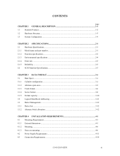
CONTENTS page CHAPTER 1 GENERAL DESCRIPTION 1-1 1.1 Standard Features ...1-2 1.2 Hardware Structure...1-5 1.3 System Configuration ...1-9 CHAPTER 2 SPECIFICATIONS 2-1 2.1 Hardware Specifications...2-1 2.1.1 Model name and part number 2-1 2.1.2 Function specifications...2-2 2.1.3 Environmental specifications 2-4 2.1.4 Error rate ...2-5 2.1.5 Reliability...2-5 2.2 SCSI Function Specifications 2-7 CHAPTER 3 DATA FORMAT 3-1 3.1 Data Space...3-1 3.1.1 Cylinder configuration...3-1 3.1.2 Alternate spare area...3-5 3.1.3 Track format...3-6 3.1.4 Sector format ...3-8 3.1.5 Format capacity ...3-10...
CONTENTS page CHAPTER 1 GENERAL DESCRIPTION 1-1 1.1 Standard Features ...1-2 1.2 Hardware Structure...1-5 1.3 System Configuration ...1-9 CHAPTER 2 SPECIFICATIONS 2-1 2.1 Hardware Specifications...2-1 2.1.1 Model name and part number 2-1 2.1.2 Function specifications...2-2 2.1.3 Environmental specifications 2-4 2.1.4 Error rate ...2-5 2.1.5 Reliability...2-5 2.2 SCSI Function Specifications 2-7 CHAPTER 3 DATA FORMAT 3-1 3.1 Data Space...3-1 3.1.1 Cylinder configuration...3-1 3.1.2 Alternate spare area...3-5 3.1.3 Track format...3-6 3.1.4 Sector format ...3-8 3.1.5 Format capacity ...3-10...
Manual/User Guide
Page 18
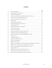
TABLES page 2.1 Function specifications...2-2 2.2 Environmental/power requirements 2-4 2.3 SCSI function specifications 2-7 3.1 Zone layout and track capacity (MAJ3364 series/MAJ3182 series 3-3 3.2 Zone layout and track capacity (MAJ3091 series...mode settings (by CHANGE DEFINITION command 5-9 5.8 Setting check list ...5-10 6.1 Self-diagnostic functions ...6-1 6.2 System-level field troubleshooting 6-14 6.3 Disk drive troubleshooting ...6-15 7.1 Definition of sense data ...7-3 8.1 MAJ3364 series, MAJ3182 series date frequency and recording density in each zone ........8-8 8.2 MAJ3091 series...
TABLES page 2.1 Function specifications...2-2 2.2 Environmental/power requirements 2-4 2.3 SCSI function specifications 2-7 3.1 Zone layout and track capacity (MAJ3364 series/MAJ3182 series 3-3 3.2 Zone layout and track capacity (MAJ3091 series...mode settings (by CHANGE DEFINITION command 5-9 5.8 Setting check list ...5-10 6.1 Self-diagnostic functions ...6-1 6.2 System-level field troubleshooting 6-14 6.3 Disk drive troubleshooting ...6-15 7.1 Definition of sense data ...7-3 8.1 MAJ3364 series, MAJ3182 series date frequency and recording density in each zone ........8-8 8.2 MAJ3091 series...
Manual/User Guide
Page 21
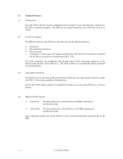
... expansion of system functions. (3) 8-bit SCSI/16-bit SCSI The IDD has 16-bit data bus width (16-bit SCSI), which meets the logical specification of the disk drive. 1.1 Standard Features (1) Compactness Since the SCSI controller circuit is embedded in synchronous mode. This is also available as follows. (4) High speed data transfer.... This allows software to the SCSI bus of connectable SCSI devices on the SCSI bus is 160 MB/s maximum in the standard 3.5 type fixed disk drive form factor, the IDD is varied as 8-bit data bus.
... expansion of system functions. (3) 8-bit SCSI/16-bit SCSI The IDD has 16-bit data bus width (16-bit SCSI), which meets the logical specification of the disk drive. 1.1 Standard Features (1) Compactness Since the SCSI controller circuit is embedded in synchronous mode. This is also available as follows. (4) High speed data transfer.... This allows software to the SCSI bus of connectable SCSI devices on the SCSI bus is 160 MB/s maximum in the standard 3.5 type fixed disk drive form factor, the IDD is varied as 8-bit data bus.

Manual/User Guide
Page 22
... perform continuous read/write operation when processing data blocks on the SCSI bus by specifying the condition of stored data to prevent a specific command from the data buffer without concerning the physical structure of the track or cylinder boundaries. Data is logical block address. The ... effective input/output operations with utilizing high data transfer capability of the SCSI bus regardless of actual data transfer rate of the disk drive. (7) Read-ahead cache feature After executing the READ command, the IDD reads automatically and stores (prefetches) the subsequent data blocks into...
... perform continuous read/write operation when processing data blocks on the SCSI bus by specifying the condition of stored data to prevent a specific command from the data buffer without concerning the physical structure of the track or cylinder boundaries. Data is logical block address. The ... effective input/output operations with utilizing high data transfer capability of the SCSI bus regardless of actual data transfer rate of the disk drive. (7) Read-ahead cache feature After executing the READ command, the IDD reads automatically and stores (prefetches) the subsequent data blocks into...

Manual/User Guide
Page 30
CHAPTER 2 SPECIFICATIONS 2.1 Hardware Specifications 2.2 SCSI Function Specifications This chapter describes specifications of the IDD and the functional specifications of the SCSI. 2.1 Hardware Specifications 2.1.1 Model name and part number Each model has a different data format and front panel type when shipped. (See Appendix D for the model name (type) and product number.) The data format can be changed by reinitializing with the user's system. C141-E103-02EN 2 - 1
CHAPTER 2 SPECIFICATIONS 2.1 Hardware Specifications 2.2 SCSI Function Specifications This chapter describes specifications of the IDD and the functional specifications of the SCSI. 2.1 Hardware Specifications 2.1.1 Model name and part number Each model has a different data format and front panel type when shipped. (See Appendix D for the model name (type) and product number.) The data format can be changed by reinitializing with the user's system. C141-E103-02EN 2 - 1

Manual/User Guide
Page 31
... rotations min-1 (rpm) Average latency time Seek time (*3) (Read/Write) Minimum Average Maximum Specification MAJ3364 series MAJ3182 series MAJ3091 series 36.4 GB 18.2 GB 9.1 GB 46.6 GB 23.3 GB 11.7 GB 5 3 2 10 5 3 14,792 14,808 13,261 188,928 to 293,888 172,032 to 293,888 10,025±0.5% ... Fast SCSI (Single-Ended) Fast 20 SCSI (Single-Ended) Fast 80 SCSI (LVD) Data transfer rate (*10) Disk drive SCSI Synchronous mode Logical data block length (*1) SCSI command specification Data buffer 12.5 W 30 s typ. (60 s max.) 30 s typ. 32/34 MEEPRML 15.35kb/mm (390...
... rotations min-1 (rpm) Average latency time Seek time (*3) (Read/Write) Minimum Average Maximum Specification MAJ3364 series MAJ3182 series MAJ3091 series 36.4 GB 18.2 GB 9.1 GB 46.6 GB 23.3 GB 11.7 GB 5 3 2 10 5 3 14,792 14,808 13,261 188,928 to 293,888 172,032 to 293,888 10,025±0.5% ... Fast SCSI (Single-Ended) Fast 20 SCSI (Single-Ended) Fast 80 SCSI (LVD) Data transfer rate (*10) Disk drive SCSI Synchronous mode Logical data block length (*1) SCSI command specification Data buffer 12.5 W 30 s typ. (60 s max.) 30 s typ. 32/34 MEEPRML 15.35kb/mm (390...

Manual/User Guide
Page 33
... Temperature (*1) Relative humidity Vibration (*2) Shock (*2) Altitute (above sea level) Power requirements Input power (*5) Specification Item MAJ3364 series MAJ3182 series MAJ3091 series MAH3182 series MAH3091 series Operating 5 to 50°C Non-operating...VDC ±5% (*6) Ready 0.75A 0.7 A Random W/R (about 80 IOPS) 0.9 A 0.8 A Ripple (*7) +5 V/+12 V 250 mVp-p (*1) For detail condition, see Section 4.1. (*2) Vibration applied to the drive is measured at near the mounting screw hole on the frame as much as possible. (*3) At random seek write/read and default on retry setting...
... Temperature (*1) Relative humidity Vibration (*2) Shock (*2) Altitute (above sea level) Power requirements Input power (*5) Specification Item MAJ3364 series MAJ3182 series MAJ3091 series MAH3182 series MAH3091 series Operating 5 to 50°C Non-operating...VDC ±5% (*6) Ready 0.75A 0.7 A Random W/R (about 80 IOPS) 0.9 A 0.8 A Ripple (*7) +5 V/+12 V 250 mVp-p (*1) For detail condition, see Section 4.1. (*2) Vibration applied to the drive is measured at near the mounting screw hole on the frame as much as possible. (*3) At random seek write/read and default on retry setting...

Manual/User Guide
Page 36
Table 2.3 SCSI function specifications Item Specification Single-ended type Ο HVD type (High Voltage Differential) × LVD type (Low Voltage Differential) Ο Electrical 160/m LVD type (Low Voltage Differential) ...Disconnection/reconnection function Ο Addressing SCSI ID 16-bit SCSI LUN (logical unit number) #0 to (12) of Section 1.1. C141-E103-02EN 2 - 7 2.2 SCSI Function Specifications Table 2.3 shows the SCSI functions provided with the IDD. Data buffer 4 MB (MC/MP) programmable multi-segment buffer (1 to 32) Data block length (Logical data...
Table 2.3 SCSI function specifications Item Specification Single-ended type Ο HVD type (High Voltage Differential) × LVD type (Low Voltage Differential) Ο Electrical 160/m LVD type (Low Voltage Differential) ...Disconnection/reconnection function Ο Addressing SCSI ID 16-bit SCSI LUN (logical unit number) #0 to (12) of Section 1.1. C141-E103-02EN 2 - 7 2.2 SCSI Function Specifications Table 2.3 shows the SCSI functions provided with the IDD. Data buffer 4 MB (MC/MP) programmable multi-segment buffer (1 to 32) Data block length (Logical data...

Manual/User Guide
Page 38
... 3.2 Logical Data Block Addressing 3.3 Defect Management This chapter explains data space definition, logical data block addressing, and defect management on or during the execution of a specific command, but user can be accessed with the logical data block addressing method described in the user space are provided in the user space. C141...
... 3.2 Logical Data Block Addressing 3.3 Defect Management This chapter explains data space definition, logical data block addressing, and defect management on or during the execution of a specific command, but user can be accessed with the logical data block addressing method described in the user space are provided in the user space. C141...

Manual/User Guide
Page 50
... are used up . The logical data block is allocated to those defective sectors included in the same cylinder are allocated to OEM Manual-SCSI Logical Specifications-for details of the alternate block allocation during the FORMAT UNIT command execution. C141-E103-02EN 3 - 13 The alternate block allocation is made. Figure 3.7 is...
... are used up . The logical data block is allocated to those defective sectors included in the same cylinder are allocated to OEM Manual-SCSI Logical Specifications-for details of the alternate block allocation during the FORMAT UNIT command execution. C141-E103-02EN 3 - 13 The alternate block allocation is made. Figure 3.7 is...

Manual/User Guide
Page 59
... shown in Figure 4.7, and the tolerance of the angle is ±5° from the IDD frame wall at the corner must be within the device specifications. c) Tightening torque of screw must be given to mount the IDD disk enclosure (DE) as follows. d) Impact caused by the electric driver must be 4 mm...
... shown in Figure 4.7, and the tolerance of the angle is ±5° from the IDD frame wall at the corner must be within the device specifications. c) Tightening torque of screw must be given to mount the IDD disk enclosure (DE) as follows. d) Impact caused by the electric driver must be 4 mm...

Manual/User Guide
Page 61
... so that the DE surface temperature does not exceed 55°C. • Cool the PCA side especially with ambient temperature measured 3 cm from the disk drive. Confirm the cooling effect by measuring temperature of DE cover 2 Read channel LSI 3 VCM/SPM Driver 4 HDC Criteria 55°C 83°C 92°C...be within a criteria listed in a cabinet is indicated with air circulation inside the cabinet. Table 4.1 Surface temperature check point No. Measurement point 1 Center of specific ICs and the DE. (4) Environmental temperature Temperature condition at installed in Table 4.1.
... so that the DE surface temperature does not exceed 55°C. • Cool the PCA side especially with ambient temperature measured 3 cm from the disk drive. Confirm the cooling effect by measuring temperature of DE cover 2 Read channel LSI 3 VCM/SPM Driver 4 HDC Criteria 55°C 83°C 92°C...be within a criteria listed in a cabinet is indicated with air circulation inside the cabinet. Table 4.1 Surface temperature check point No. Measurement point 1 Center of specific ICs and the DE. (4) Environmental temperature Temperature condition at installed in Table 4.1.

Manual/User Guide
Page 66
...of the +5 VDC power supply line to the IDD must be designed with a setting terminal on the IDD power supply unit. The specification of this noise filter is as follows: • Attenuation: 40 dB or more at 10 MHz • Circuit construction: T-configuration ... sequentially. (5) Power supply to SCSI terminating resistor If power for this command specification, refer to SCSI Logical Interface Specifications. Therefore, if more than 12-second intervals to Subsection 1.4.2 in SCSI Physical Interface Specifications. (6) Noise filter To eliminate AC line noise, a noise filter should be...
...of the +5 VDC power supply line to the IDD must be designed with a setting terminal on the IDD power supply unit. The specification of this noise filter is as follows: • Attenuation: 40 dB or more at 10 MHz • Circuit construction: T-configuration ... sequentially. (5) Power supply to SCSI terminating resistor If power for this command specification, refer to SCSI Logical Interface Specifications. Therefore, if more than 12-second intervals to Subsection 1.4.2 in SCSI Physical Interface Specifications. (6) Noise filter To eliminate AC line noise, a noise filter should be...

Manual/User Guide
Page 68
... the signal assignments on the physical/electrical requirements of DC power supply. Figure 4.17 shows the SCSI connector. See Section C.2 in the SCSI Physical Interface Specifications. Figure 4.18 Power supply connector (16-bit SCSI model) C141-E103-02EN 4 - 15 For details on the SCSI connector.
... the signal assignments on the physical/electrical requirements of DC power supply. Figure 4.17 shows the SCSI connector. See Section C.2 in the SCSI Physical Interface Specifications. Figure 4.18 Power supply connector (16-bit SCSI model) C141-E103-02EN 4 - 15 For details on the SCSI connector.

Manual/User Guide
Page 72
...IDD has been switched on (it is identical in indication to the LED on the front of the disk drive. For details of indication can be connected to the CN2-21, 22 pin (LED [V] and -LED...A12 is connected to the GND, or the CN2-9 and CN2-10 are short-circuited.) A signal for driving the LED is output. 74LS06 or equivalent 150 Ω (IDD) NC1-A2 IMPORTANT This signal is temporarily...and CN1-A8.) C141-E103-02EN 4 - 19 The meaning of command, refer to SCSI Logical Interface Specifications. 2. This signal is temporarily driven at the GND level when the micro program reads the SCSI ID ...
...IDD has been switched on (it is identical in indication to the LED on the front of the disk drive. For details of indication can be connected to the CN2-21, 22 pin (LED [V] and -LED...A12 is connected to the GND, or the CN2-9 and CN2-10 are short-circuited.) A signal for driving the LED is output. 74LS06 or equivalent 150 Ω (IDD) NC1-A2 IMPORTANT This signal is temporarily...and CN1-A8.) C141-E103-02EN 4 - 19 The meaning of command, refer to SCSI Logical Interface Specifications. 2. This signal is temporarily driven at the GND level when the micro program reads the SCSI ID ...

Manual/User Guide
Page 76
For details on the connector. See Section C.5 in SCSI Physical Interface Specifications. Figure 4.25 shows the SCSI connector. (2) SCSI connector and power supply connector a. SCA type SCSI The connector for signal assignments on the physical/electrical requirements of the interface signals, refer to Sections 1.3 and 1.4 in Appendix C for the SCSI bus is an unshielded SCA-2 connector conforming to SCSI-3 type which has two 40-pin rows spaced 1.27 mm (0.05 inch) apart. Figure 4.25 SCA2 type SCSI connector C141-E103-02EN 4 - 23
For details on the connector. See Section C.5 in SCSI Physical Interface Specifications. Figure 4.25 shows the SCSI connector. (2) SCSI connector and power supply connector a. SCA type SCSI The connector for signal assignments on the physical/electrical requirements of the interface signals, refer to Sections 1.3 and 1.4 in Appendix C for the SCSI bus is an unshielded SCA-2 connector conforming to SCSI-3 type which has two 40-pin rows spaced 1.27 mm (0.05 inch) apart. Figure 4.25 SCA2 type SCSI connector C141-E103-02EN 4 - 23
