

Manual/User Guide
Page 6
..., MAF series), MAE3182LC/LP, MAE3091LC/LP, (hereafter, MAE series), and MAG3182LC/LP/MC/MP, MAG3091LC/LP/MC/MP (hereafter, MAG series), 3.5-inch fixed disk drives with an embedded SCSI controller. The model numbers have a basic understanding of this manual. This manual details the specifications ...and functions of the MAF series, MAE series and MAG series disk drives and their installation environment. This manual ...
..., MAF series), MAE3182LC/LP, MAE3091LC/LP, (hereafter, MAE series), and MAG3182LC/LP/MC/MP, MAG3091LC/LP/MC/MP (hereafter, MAG series), 3.5-inch fixed disk drives with an embedded SCSI controller. The model numbers have a basic understanding of this manual. This manual details the specifications ...and functions of the MAF series, MAE series and MAG series disk drives and their installation environment. This manual ...

Manual/User Guide
Page 8
Fujitsu is defined as a failure requiring adjustments, repairs, or replacement. Note 1: Model names M AF 3 364 LC transfer transfer Interface types LC: LVD, 16-bit SCSI SCA2 connector LP: LVD, 16-bit SCSI 68 ... MAF3364 MAF3364LC, MAF3364LP, MAF3364MC, MAF3364MP MAG3182 MAG3182LC, MAG3182LP, MAG3182MC, MAG3182MP MAG3091 MAG3091LC, MAG3091LP, MAG3091MC, MAG3091MP C141-E064-03EN vii However, in this manual, the typical model names (Note 2) are used unless otherwise noted. The suffix of the model name of the disk drive varies depending on the electrical requirements, capacity,...
Fujitsu is defined as a failure requiring adjustments, repairs, or replacement. Note 1: Model names M AF 3 364 LC transfer transfer Interface types LC: LVD, 16-bit SCSI SCA2 connector LP: LVD, 16-bit SCSI 68 ... MAF3364 MAF3364LC, MAF3364LP, MAF3364MC, MAF3364MP MAG3182 MAG3182LC, MAG3182LP, MAG3182MC, MAG3182MP MAG3091 MAG3091LC, MAG3091LP, MAG3091MC, MAG3091MP C141-E064-03EN vii However, in this manual, the typical model names (Note 2) are used unless otherwise noted. The suffix of the model name of the disk drive varies depending on the electrical requirements, capacity,...

Manual/User Guide
Page 12
CONTENTS page CHAPTER 1 GENERAL DESCRIPTION 1-1 1.1 Standard Features ...1-2 1.2 Hardware Structure...1-5 1.3 System Configuration...1-10 CHAPTER 2 SPECIFICATIONS 2-1 2.1 Hardware Specifications 2-1 2.1.1 Model name and part number 2-1 2.1.2 Function specifications 2-2 2.1.3 Environmental specifications 2-4 2.1.4 Error rate...2-5 2.1.5 Reliability ...2-5 2.2 SCSI Function Specifications 2-7 CHAPTER 3 DATA FORMAT 3-1 3.1 Data Space...3-1 3.1.1 Cylinder configuration...3-1 3.1.2 Alternate spare area ...3-5 3.1.3 Track ...
CONTENTS page CHAPTER 1 GENERAL DESCRIPTION 1-1 1.1 Standard Features ...1-2 1.2 Hardware Structure...1-5 1.3 System Configuration...1-10 CHAPTER 2 SPECIFICATIONS 2-1 2.1 Hardware Specifications 2-1 2.1.1 Model name and part number 2-1 2.1.2 Function specifications 2-2 2.1.3 Environmental specifications 2-4 2.1.4 Error rate...2-5 2.1.5 Reliability ...2-5 2.2 SCSI Function Specifications 2-7 CHAPTER 3 DATA FORMAT 3-1 3.1 Data Space...3-1 3.1.1 Cylinder configuration...3-1 3.1.2 Alternate spare area ...3-5 3.1.3 Track ...

Manual/User Guide
Page 13
...Requirements 4-16 68 pin connector 16-bit model (LP/MP 4-16 SCA2 type SCSI model (LC/MC 4-24 Cable connector requirements 4-28 External operator panel 4-29 CHAPTER 5 INSTALLATION 5-1 5.1 Notes on Handling Drives 5-1 5.2 Connections...5-3 5.3 Setting Terminals...5-5 ... 5-12 5.6.1 Confirming initial operations 5-12 5.6.2 Checking SCSI connection 5-13 5.6.3 Formatting ...5-16 5.6.4 Setting parameters ...5-18 5.7 Dismounting Drives ...5-22 CHAPTER 6 DIAGNOSTICS AND MAINTENANCE 6-1 6.1 Diagnostics ...6-1 6.1.1 Self-diagnostics ...6-1 6.1.2 Test programs ...6-4 6.2 Maintenance Information...
...Requirements 4-16 68 pin connector 16-bit model (LP/MP 4-16 SCA2 type SCSI model (LC/MC 4-24 Cable connector requirements 4-28 External operator panel 4-29 CHAPTER 5 INSTALLATION 5-1 5.1 Notes on Handling Drives 5-1 5.2 Connections...5-3 5.3 Setting Terminals...5-5 ... 5-12 5.6.1 Confirming initial operations 5-12 5.6.2 Checking SCSI connection 5-13 5.6.3 Formatting ...5-16 5.6.4 Setting parameters ...5-18 5.7 Dismounting Drives ...5-22 CHAPTER 6 DIAGNOSTICS AND MAINTENANCE 6-1 6.1 Diagnostics ...6-1 6.1.1 Self-diagnostics ...6-1 6.1.2 Test programs ...6-4 6.2 Maintenance Information...

Manual/User Guide
Page 14
A.2 Locations of Connectors and Setting Terminals (LP/MP models: 68 pin type LVD 16-bit SCSI A-3 APPENDIX B SETTING TERMINALS B-1 B.1 Setting Terminals...B-2 APPENDIX C CONNECTOR SIGNAL ALLOCATION C-1 C.1 SCSI Connector Signal Allocation: SCA2 type LVD 16-bit SCSI C-2 C.2 SCSI Connector Signal Allocation: 68 pin type LVD 16-bit SCSI C-3 APPENDIX D MODEL NAMES AND PRODUCT NUMBERS D-1 D.1 Model Names and Product Numbers D-2 Index...IN-1 C141-E064-03EN xiii
A.2 Locations of Connectors and Setting Terminals (LP/MP models: 68 pin type LVD 16-bit SCSI A-3 APPENDIX B SETTING TERMINALS B-1 B.1 Setting Terminals...B-2 APPENDIX C CONNECTOR SIGNAL ALLOCATION C-1 C.1 SCSI Connector Signal Allocation: SCA2 type LVD 16-bit SCSI C-2 C.2 SCSI Connector Signal Allocation: 68 pin type LVD 16-bit SCSI C-3 APPENDIX D MODEL NAMES AND PRODUCT NUMBERS D-1 D.1 Model Names and Product Numbers D-2 Index...IN-1 C141-E064-03EN xiii

Manual/User Guide
Page 16
...and terminals location (LP/MP 4-16 4.19 16-bit SCSI interface connector 4-17 4.20 Power supply connector (16-bit SCSI model 4-17 4.21 External operator panel connector (CN1 4-18 4.22 External operator panel connector (CN2 4-19 4.23 16-bit SCSI ID external input 4-20 4.24 Output signal for ...external LED 4-21 4.25 SCSI cables connection 4-23 4.26 Connectors and terminals location of SCA2 type SCSI model 4-24 4.27 SCA2 type SCSI ...
...and terminals location (LP/MP 4-16 4.19 16-bit SCSI interface connector 4-17 4.20 Power supply connector (16-bit SCSI model 4-17 4.21 External operator panel connector (CN1 4-18 4.22 External operator panel connector (CN2 4-19 4.23 16-bit SCSI ID external input 4-20 4.24 Output signal for ...external LED 4-21 4.25 SCSI cables connection 4-23 4.26 Connectors and terminals location of SCA2 type SCSI model 4-24 4.27 SCA2 type SCSI ...

Manual/User Guide
Page 17
...: CN2...B-2 C.1 SCSI connector (SCA2 type LVD 16-bit SCSI): CN1 C-2 C.2 SCSI connector (68 pin type LVD 16-bit SCSI): CN1 C-3 D.1 MAE, MAF and MAG series model names and product numbers D-2 xvi C141-E064-03EN
...: CN2...B-2 C.1 SCSI connector (SCA2 type LVD 16-bit SCSI): CN1 C-2 C.2 SCSI connector (68 pin type LVD 16-bit SCSI): CN1 C-3 D.1 MAE, MAF and MAG series model names and product numbers D-2 xvi C141-E064-03EN
Manual/User Guide
Page 19
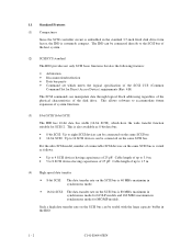
... of up to 16 SCSI devices can be useful with the large capacity buffer in the IDD. 1 - 2 C141-E064-03EN For the ultra SCSI model, number of connectable SCSI devices on the same SCSI bus is varied as 8-bit data bus. • 8-bit SCSI: Up to eight SCSI devices ...8226; Disconnection/reselection • Data bus parity • Command set which have the wide transfer function suitable for MC/MP models. This allows software to the SCSI bus of the disk drive. The IDD can be connected directly to accommodate future expansion of system functions. (3) 8-bit SCSI/16-bit SCSI The IDD...
... of up to 16 SCSI devices can be useful with the large capacity buffer in the IDD. 1 - 2 C141-E064-03EN For the ultra SCSI model, number of connectable SCSI devices on the same SCSI bus is varied as 8-bit data bus. • 8-bit SCSI: Up to eight SCSI devices ...8226; Disconnection/reselection • Data bus parity • Command set which have the wide transfer function suitable for MC/MP models. This allows software to the SCSI bus of the disk drive. The IDD can be connected directly to accommodate future expansion of system functions. (3) 8-bit SCSI/16-bit SCSI The IDD...

Manual/User Guide
Page 25
Each model contains following number of disks and heads MAF3364 MAG3182 0 1 2 3 4 5 6 7 12 13 14 15 16 17 18 Head No. 0 1 2 3 4 5 6 7 8 9 MAE3091 0 1 2 3 Figure 1.7 Disk/head configuration MAG3091 0 1 2 3 4 MAE3182 0 1 2 3 4 5 6 7 1 - 8 C141-E064-03EN MAF3364: 10 MAE3182: 4 MAE3091: 2 MAG3182: 5 MAG3091: 3 (2) Heads The MR (Magnet - Figure 1.7 shows the ...
Each model contains following number of disks and heads MAF3364 MAG3182 0 1 2 3 4 5 6 7 12 13 14 15 16 17 18 Head No. 0 1 2 3 4 5 6 7 8 9 MAE3091 0 1 2 3 Figure 1.7 Disk/head configuration MAG3091 0 1 2 3 4 MAE3182 0 1 2 3 4 5 6 7 1 - 8 C141-E064-03EN MAF3364: 10 MAE3182: 4 MAE3091: 2 MAG3182: 5 MAG3091: 3 (2) Heads The MR (Magnet - Figure 1.7 shows the ...

Manual/User Guide
Page 30
C141-E064-03EN 2 - 1 CHAPTER 2 SPECIFICATIONS 2.1 Hardware Specifications 2.2 SCSI Function Specifications This chapter describes specifications of the IDD and the functional specifications of the SCSI. 2.1 Hardware Specifications 2.1.1 Model name and part number Each model has a different data format and front panel type when shipped. (See Appendix D for the model name (type) and product number.) The data format can be changed by reinitializing with the user's system.
C141-E064-03EN 2 - 1 CHAPTER 2 SPECIFICATIONS 2.1 Hardware Specifications 2.2 SCSI Function Specifications This chapter describes specifications of the IDD and the functional specifications of the SCSI. 2.1 Hardware Specifications 2.1.1 Model name and part number Each model has a different data format and front panel type when shipped. (See Appendix D for the model name (type) and product number.) The data format can be changed by reinitializing with the user's system.
Manual/User Guide
Page 31
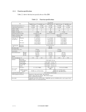
...) conformity (SCSI-2 ANSI X3T9.2/86-109 Rev. 10h) command support SCSI-3 command partial support 2 MB FIFO ring buffer (LC/LP models), 4 MB FIFO ring buffer (MC/MP models), multi-segment buffer: Segment count 1 to 215,040 0.7 ms (Read)/ 0.9 ms (Write) 5.5 ms (Read)/ 6.0 ms (... Fast 20 SCSI (Single-Ended) Fast 80 SCSI (LVD) Data transfer rate (*10) Disk drive SCSI Synchronous mode Logical data block length (*1) SCSI command specification Data buffer MAE3182 series MAE3091 series 18.2 GB 9.1 GB 23.1 GB 11.5 GB 4 2 8 4 12,000 143,360 to 217,600 7,200±0.5% 4.167 msec 0.7...
...) conformity (SCSI-2 ANSI X3T9.2/86-109 Rev. 10h) command support SCSI-3 command partial support 2 MB FIFO ring buffer (LC/LP models), 4 MB FIFO ring buffer (MC/MP models), multi-segment buffer: Segment count 1 to 215,040 0.7 ms (Read)/ 0.9 ms (Write) 5.5 ms (Read)/ 6.0 ms (... Fast 20 SCSI (Single-Ended) Fast 80 SCSI (LVD) Data transfer rate (*10) Disk drive SCSI Synchronous mode Logical data block length (*1) SCSI command specification Data buffer MAE3182 series MAE3091 series 18.2 GB 9.1 GB 23.1 GB 11.5 GB 4 2 8 4 12,000 143,360 to 217,600 7,200±0.5% 4.167 msec 0.7...

Manual/User Guide
Page 36
... type Position where the terminating × (*1) resistor is mounted on the PCA Differential type Position where the terminating × resistor is mounted on MC/MP models. (*3) Refer to #15 (Jumper selection) #0 fixed Data transfer 8-bit SCSI (Single-Ended type) (Synchronous (LVD type) mode) 16-bit SCSI (Single-Ended type) (LVD type...
... type Position where the terminating × (*1) resistor is mounted on the PCA Differential type Position where the terminating × resistor is mounted on MC/MP models. (*3) Refer to #15 (Jumper selection) #0 fixed Data transfer 8-bit SCSI (Single-Ended type) (Synchronous (LVD type) mode) 16-bit SCSI (Single-Ended type) (LVD type...

Manual/User Guide
Page 45
... listed in Figure 3.6 is listed in Figure 3.6. 3.1.4 Sector format Each sector on the track consists of formatting (initializing) is written. 3 - 8 C141-E064-03EN LC/LP models SCT SB LBA PLO G1 Sync 4 4 DATA m BCRC ECC SCT 2 40 PAD PAD 12 SCT SB LBA DATA 1 Servo SB DATA 2 BCRC ECC SCT PLO... G1 Sync 4 4 PAD PAD 12 PLO G1 Sync 4 2 40 PAD PAD 13 MC/MP models SCT SB PLO G1 Sync 4 DATA m BCRC ECC SCT 4 40 PAD PAD 12 SCT SB DATA 1 Servo SB DATA 2 BCRC ECC SCT PLO G1 Sync...
... listed in Figure 3.6 is listed in Figure 3.6. 3.1.4 Sector format Each sector on the track consists of formatting (initializing) is written. 3 - 8 C141-E064-03EN LC/LP models SCT SB LBA PLO G1 Sync 4 4 DATA m BCRC ECC SCT 2 40 PAD PAD 12 SCT SB LBA DATA 1 Servo SB DATA 2 BCRC ECC SCT PLO... G1 Sync 4 4 PAD PAD 12 PLO G1 Sync 4 2 40 PAD PAD 13 MC/MP models SCT SB PLO G1 Sync 4 DATA m BCRC ECC SCT 4 40 PAD PAD 12 SCT SB DATA 1 Servo SB DATA 2 BCRC ECC SCT PLO G1 Sync...

Manual/User Guide
Page 46
...Figure 3.6 is written in this field. (4) LBA The logical block address is written in this field, but it is not written with MP/MC models because it is appended to BCRC field information. (5) Data field User data is stored in the MODE SELECT command. The 4-byte error detection code ...is a 2-byte error detection code. C141-E064-03EN 3 - 9 It is possible to on-the-fly correct the single burst errors with the MC/MP models. (7) ECC 40-byte data error detection/correction code for each logical block can be detected. This field includes the variation by rotation and circuit delay...
...Figure 3.6 is written in this field. (4) LBA The logical block address is written in this field, but it is not written with MP/MC models because it is appended to BCRC field information. (5) Data field User data is stored in the MODE SELECT command. The 4-byte error detection code ...is a 2-byte error detection code. C141-E064-03EN 3 - 9 It is possible to on-the-fly correct the single burst errors with the MC/MP models. (7) ECC 40-byte data error detection/correction code for each logical block can be detected. This field includes the variation by rotation and circuit delay...

Manual/User Guide
Page 47
...zone × number of tracks (heads) × number of alternate cylinders] ÷ [number of logical data blocks are used. Table 3.4 Format capacity Model Data heads Data block length MAE3182 series 8 MAE3091 series 4 MAF3364 series 19 512 MAG3182 series 10 MAG3091 series 5 User blocks 35,700,480 17,826...,240 71,161,520 35,694,860 17,827,698 Format capacity (GB) 18.2 9.1 36.4 18.2 9.1 Note: Total number of spare sectors is the general formula to the logical data block or the size of tracks (heads) - 3.1.5 ...
...zone × number of tracks (heads) × number of alternate cylinders] ÷ [number of logical data blocks are used. Table 3.4 Format capacity Model Data heads Data block length MAE3182 series 8 MAE3091 series 4 MAF3364 series 19 512 MAG3182 series 10 MAG3091 series 5 User blocks 35,700,480 17,826...,240 71,161,520 35,694,860 17,827,698 Format capacity (GB) 18.2 9.1 36.4 18.2 9.1 Note: Total number of spare sectors is the general formula to the logical data block or the size of tracks (heads) - 3.1.5 ...

Manual/User Guide
Page 69
4.3 Connection Requirements 4.3.1 68 pin connector 16-bit SCSI model (LP/MP) (1) Connectors Figures 4.18 show the locations of connectors and terminals on the 68 pin connector type 16bit SCSI (LP/MP) model. • Power supply connector • SCSI connector • External operator panel connector External operator panel connector (CN2) Power supply connector (CN1) External operator panel connector (CN1) SCSI connector (CN1) Figure 4.18 Connectors and terminals location (LP/MP) 4 - 16 C141-E064-03EN
4.3 Connection Requirements 4.3.1 68 pin connector 16-bit SCSI model (LP/MP) (1) Connectors Figures 4.18 show the locations of connectors and terminals on the 68 pin connector type 16bit SCSI (LP/MP) model. • Power supply connector • SCSI connector • External operator panel connector External operator panel connector (CN2) Power supply connector (CN1) External operator panel connector (CN1) SCSI connector (CN1) Figure 4.18 Connectors and terminals location (LP/MP) 4 - 16 C141-E064-03EN

Manual/User Guide
Page 70
... on the physical/electrical requirements of DC power supply. See Section C.2 in the SCSI Physical Interface Specifications. Figure 4.20 Power supply connector (16-bit SCSI model) C141-E064-03EN 4 - 17 For details on the SCSI connector.
... on the physical/electrical requirements of DC power supply. See Section C.2 in the SCSI Physical Interface Specifications. Figure 4.20 Power supply connector (16-bit SCSI model) C141-E064-03EN 4 - 17 For details on the SCSI connector.

Manual/User Guide
Page 77
4.3.2 SCA2 type SCSI model (LC/MC) (1) Connectors Figure 4.26 shows the locations of SCA2 type SCSI model 4 - 24 C141-E064-03EN SCSI connector (including power supply connector) SCSI connector Figure 4.26 Connectors and terminals location of connectors and terminals on the SCA2 type SCSI model.
4.3.2 SCA2 type SCSI model (LC/MC) (1) Connectors Figure 4.26 shows the locations of SCA2 type SCSI model 4 - 24 C141-E064-03EN SCSI connector (including power supply connector) SCSI connector Figure 4.26 Connectors and terminals location of connectors and terminals on the SCA2 type SCSI model.

Manual/User Guide
Page 81
Table 4.2 Recommended components for connection Applicable model Name Par number LP/MP LC/MC SCSI cable (CN1) Cable socket 786090-7 (closed-end type) Signal cable - Power supply cable Cable socket...CN1) housing FCN-723J012/2M Contact FCN-723J-G/AM Cable AWG26 to disable. 4.3.3 Cable connector requirements Table 4.2 lists the recommended components cable connection. AMP Fujitsu Limited Fujitsu Limited Fujitsu Limited Fujitsu Limited AMP Reference (Figures 4.25 and 4.30) S1 S2 S3 S4 (1) SCSI cable See Section 1.3, "Physical Requirements", and Section 1.4, "Electrical ...
Table 4.2 Recommended components for connection Applicable model Name Par number LP/MP LC/MC SCSI cable (CN1) Cable socket 786090-7 (closed-end type) Signal cable - Power supply cable Cable socket...CN1) housing FCN-723J012/2M Contact FCN-723J-G/AM Cable AWG26 to disable. 4.3.3 Cable connector requirements Table 4.2 lists the recommended components cable connection. AMP Fujitsu Limited Fujitsu Limited Fujitsu Limited Fujitsu Limited AMP Reference (Figures 4.25 and 4.30) S1 S2 S3 S4 (1) SCSI cable See Section 1.3, "Physical Requirements", and Section 1.4, "Electrical ...

Manual/User Guide
Page 93
... when the screws are tightened (see Section 5.3. For setting terminals location, see Figure 4.8). • When mounting the drive, be used. 5 - 10 C141-E064-03EN Fix the drive by using four mounting holes of both sides: 3 ×2, bottom: 4). See Subsection 4.2 for the details of ... PI) not connected Short Open Short Open Short Open Short Open Short Open LP/MP models 5.4.2 Mounting procedures Since mounting the drive depends on the system side after tightening the screws. 5.4 Mounting Drives 5.4.1 Check before mounting Reconfirm if the setting terminals are shown below.
... when the screws are tightened (see Section 5.3. For setting terminals location, see Figure 4.8). • When mounting the drive, be used. 5 - 10 C141-E064-03EN Fix the drive by using four mounting holes of both sides: 3 ×2, bottom: 4). See Subsection 4.2 for the details of ... PI) not connected Short Open Short Open Short Open Short Open Short Open LP/MP models 5.4.2 Mounting procedures Since mounting the drive depends on the system side after tightening the screws. 5.4 Mounting Drives 5.4.1 Check before mounting Reconfirm if the setting terminals are shown below.

