
Operation Manual
Page 6
v Preface This manual explains how to the Operator's Guide for volume filing, using charge-coupled device (CCD) color image sensors. Refer to clean and maintain the fi-4750C image scanner. The fi-4750C is a highly functional color image scanner developed for basic information about the fi-4750C. This scanner features duplex scanning and high quality color image processing with an automatic document feeder (ADF).
v Preface This manual explains how to the Operator's Guide for volume filing, using charge-coupled device (CCD) color image sensors. Refer to clean and maintain the fi-4750C image scanner. The fi-4750C is a highly functional color image scanner developed for basic information about the fi-4750C. This scanner features duplex scanning and high quality color image processing with an automatic document feeder (ADF).

Operation Manual
Page 20
When the cause of the SCSI board. Alternatively, replace the current cable with one recommended by the manufacturer of the alarm has been corrected, the scanner automatically resumes operation once power is displayed, turn Off system power and then turn it On again. DESCRIPTION NOTE When this message is turned On again. 1-11
When the cause of the SCSI board. Alternatively, replace the current cable with one recommended by the manufacturer of the alarm has been corrected, the scanner automatically resumes operation once power is displayed, turn Off system power and then turn it On again. DESCRIPTION NOTE When this message is turned On again. 1-11

Operation Manual
Page 49
Are the Document bed, NO Document holding pad, Clean the dirty parts. missing NO Is the scanner on it ? TROUBLESHOOTING 4-9 glass and sheet guides clean? (See p. 2-5, p. 2-7, p. 2-10) YES During rear read operation with the ADF, is the top of the ADF being ... there anything heavy on an even NO and flat surface or are distorted or unclear. YES Place the scanner on it . Contact the manufacturer's authorized service center. 6 Symptom Images are any rubber feet of the scanner missing? YES Do not press the top of the ADF or put anything heavy on a flat, even...
Are the Document bed, NO Document holding pad, Clean the dirty parts. missing NO Is the scanner on it ? TROUBLESHOOTING 4-9 glass and sheet guides clean? (See p. 2-5, p. 2-7, p. 2-10) YES During rear read operation with the ADF, is the top of the ADF being ... there anything heavy on an even NO and flat surface or are distorted or unclear. YES Place the scanner on it . Contact the manufacturer's authorized service center. 6 Symptom Images are any rubber feet of the scanner missing? YES Do not press the top of the ADF or put anything heavy on a flat, even...
Operating Guide
Page 7
... AND OPTIONS SETUP MODE It also contains a Glossary of the fi-4750C. Refer to use the fi-4750C image scanner. v The fi-4750C is a very fast and highly functional color image scanner developed for information about the routine operation of Terms and an Index. This scanner features high-speed duplex scanning with an automatic document feeder (ADF). This manual contains chapters on OPERATING INSTRUCTIONS...
... AND OPTIONS SETUP MODE It also contains a Glossary of the fi-4750C. Refer to use the fi-4750C image scanner. v The fi-4750C is a very fast and highly functional color image scanner developed for information about the routine operation of Terms and an Index. This scanner features high-speed duplex scanning with an automatic document feeder (ADF). This manual contains chapters on OPERATING INSTRUCTIONS...

Operating Guide
Page 28
...Shipping Lock (Position for shipment) CAUTION Before moving or storing the scanner, make sure that the left side of the scanner (where the ADF is attached) extends from being damaged during shipping, the carrier unit is set the image scanner upside down or on the edge of this Shipping Lock as explained ...below. 1 Place the image scanner on its side. CAUTION Do not let the scanner hang more than 20 cm (8 in .) over the edge of the ...
...Shipping Lock (Position for shipment) CAUTION Before moving or storing the scanner, make sure that the left side of the scanner (where the ADF is attached) extends from being damaged during shipping, the carrier unit is set the image scanner upside down or on the edge of this Shipping Lock as explained ...below. 1 Place the image scanner on its side. CAUTION Do not let the scanner hang more than 20 cm (8 in .) over the edge of the ...

Operating Guide
Page 30
Factory default for the SCSI ID is On. The factory default for the SCSI terminator is 5. If the scanner is the same as the other device, change the ID via the operator panel. 2. Back of two devices, turn the scanner termination Off via the operator panel or change the ID of the other device. 2-5 If the ID of the scanner is in the middle of the daisy chain or of the image scanner Interface cables To the host system NOTICES 1. Connecting the interface cables Connect the SCSI interface cables and secure them.
Factory default for the SCSI ID is On. The factory default for the SCSI terminator is 5. If the scanner is the same as the other device, change the ID via the operator panel. 2. Back of two devices, turn the scanner termination Off via the operator panel or change the ID of the other device. 2-5 If the ID of the scanner is in the middle of the daisy chain or of the image scanner Interface cables To the host system NOTICES 1. Connecting the interface cables Connect the SCSI interface cables and secure them.

Operating Guide
Page 31
Mounting the Stacker Mount the stacker using the following procedure. 1 Mount the stacker. Stacker Pin (inside) Claw 2-6 Hook the pins on the stacker to the claws on the image scanner.
Mounting the Stacker Mount the stacker using the following procedure. 1 Mount the stacker. Stacker Pin (inside) Claw 2-6 Hook the pins on the stacker to the claws on the image scanner.

Operating Guide
Page 62
Options The following table lists options available for more information. 6-2 Name Video Interface Board Option P/N CA02956-2391 IPC-4D CA02919-0521 Remarks Image Processing Circuit One per unit Contact your Fujitsu sales agent for the scanner.
Options The following table lists options available for more information. 6-2 Name Video Interface Board Option P/N CA02956-2391 IPC-4D CA02919-0521 Remarks Image Processing Circuit One per unit Contact your Fujitsu sales agent for the scanner.

Operating Guide
Page 71
... 7-2 Tolerance: No/10/15/20mm No 3 IPC pre-setting Scanner automatically sets the recommended reading parameters. 3 sets of picking. Note that the new setting is made valid after the last 27 values from document Insertion to 1999 sec 30 sec 7 ADF front offset setting* ... +3 mm Offset: H: 0 mm V: 0 mm 10 IPC status display Displays whether or not the image processing board (IPC-4D) is installed. --- --- 11 SCSI ID setting The SCSI ID is detected by checking the document No/Yes No length and/or paper thickness.** 2 Length check =No/10/15/20 mm Specifies the...
... 7-2 Tolerance: No/10/15/20mm No 3 IPC pre-setting Scanner automatically sets the recommended reading parameters. 3 sets of picking. Note that the new setting is made valid after the last 27 values from document Insertion to 1999 sec 30 sec 7 ADF front offset setting* ... +3 mm Offset: H: 0 mm V: 0 mm 10 IPC status display Displays whether or not the image processing board (IPC-4D) is installed. --- --- 11 SCSI ID setting The SCSI ID is detected by checking the document No/Yes No length and/or paper thickness.** 2 Length check =No/10/15/20 mm Specifies the...

Operating Guide
Page 72
... R/G/B/W G Select this IPC-4D board or the image processing circuit built in high quality. (Continued) No Item Description Selectable parameters Default 14 Select Interface Selects the interface when the scanner has a board in unicolor. Auto/SCSI/Tps Auto 15 Display TPS Board ID Number Displays the...Adjusts the edge areas to be erased from 17 ADF Edge Erasing the image scanned by automatic offset adjustment. ** Some restrictions apply to be erased from the value adjusted by the automatic document feeder (ADF). Standard/IPC4D Standard Adjusts the edge areas to the ...
... R/G/B/W G Select this IPC-4D board or the image processing circuit built in high quality. (Continued) No Item Description Selectable parameters Default 14 Select Interface Selects the interface when the scanner has a board in unicolor. Auto/SCSI/Tps Auto 15 Display TPS Board ID Number Displays the...Adjusts the edge areas to be erased from 17 ADF Edge Erasing the image scanned by automatic offset adjustment. ** Some restrictions apply to be erased from the value adjusted by the automatic document feeder (ADF). Standard/IPC4D Standard Adjusts the edge areas to the ...

Operating Guide
Page 75
... as follows: 1 Press "Next" or "Previous" and let the scanner display Screen 43. 2 At Screen 43, press or to select the pre-Setting and press to activate the pre-setting. Then the scanner displays Screen 43-1. NOTICES The following IPC pre-settings can be selected ...when IPC-4D is installed: Preset 1: Captures texts printed on the colored background Preset 2: Produces an image with good contrast Preset 3: OCR Smoothing Preset 4: Image Smoothing Preset 5: Dither The following...
... as follows: 1 Press "Next" or "Previous" and let the scanner display Screen 43. 2 At Screen 43, press or to select the pre-Setting and press to activate the pre-setting. Then the scanner displays Screen 43-1. NOTICES The following IPC pre-settings can be selected ...when IPC-4D is installed: Preset 1: Captures texts printed on the colored background Preset 2: Produces an image with good contrast Preset 3: OCR Smoothing Preset 4: Image Smoothing Preset 5: Dither The following...

Operating Guide
Page 79
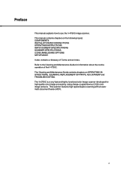
... Screen 50. and let the (An example) 2 Screen 50 displays the IPC option installed and the total image memory installed. 3 Press to return. 12. SCSI ID Setting 1 Press "Next" or "Previous" scanner display Screen 51. Then press to activate the setting. 3 Press to return. 11. and let the 2 At Screen 52, ...press or Terminator. and let the 2 At Screen 51, press or to return. 7-10 to select to activate the 3 Press to select SCSI ID. Then press setting. SCSI Terminator Setting 1 Press "Next" or "Previous" scanner display Screen 52. 10.
... Screen 50. and let the (An example) 2 Screen 50 displays the IPC option installed and the total image memory installed. 3 Press to return. 12. SCSI ID Setting 1 Press "Next" or "Previous" scanner display Screen 51. Then press to activate the setting. 3 Press to return. 11. and let the 2 At Screen 52, ...press or Terminator. and let the 2 At Screen 51, press or to return. 7-10 to select to activate the 3 Press to select SCSI ID. Then press setting. SCSI Terminator Setting 1 Press "Next" or "Previous" scanner display Screen 52. 10.
Operating Guide
Page 81
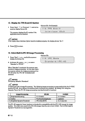
..., the display shows "ID=7". 2 Press to select "Standard" or "IPC4D". NOTICE fi-4750C has built-in the fi-4750C. The fi-4750C Built-in image processing. 15. NOTICE If the Fujitsu video Interface Option board is larger than the one in Image Processing. When "Standard" is selected, the scanner uses its built-in Dynamic Threshold is supported both by the...
..., the display shows "ID=7". 2 Press to select "Standard" or "IPC4D". NOTICE fi-4750C has built-in the fi-4750C. The fi-4750C Built-in image processing. 15. NOTICE If the Fujitsu video Interface Option board is larger than the one in Image Processing. When "Standard" is selected, the scanner uses its built-in Dynamic Threshold is supported both by the...

Operating Guide
Page 82
... change the top setting. With (+:Up), the area is set upward from the bottom edge of the image. Then press to activate the setting. Then press to activate the setting. The scanner displays Screen 57-5. 7 At Screen 57-5, press or to change the top setting. Then press . ...With (-:Down), the area is set downward from the bottom edge of the image. The value changes in 1 mm units. The value changes in 1 mm units. The scanner displays Screen 57-3. 5 At Screen 57-3, press or to change the bottom setting. Then press to ...
... change the top setting. With (+:Up), the area is set upward from the bottom edge of the image. Then press to activate the setting. Then press to activate the setting. The scanner displays Screen 57-5. 7 At Screen 57-5, press or to change the top setting. Then press . ...With (-:Down), the area is set downward from the bottom edge of the image. The value changes in 1 mm units. The value changes in 1 mm units. The scanner displays Screen 57-3. 5 At Screen 57-3, press or to change the bottom setting. Then press to ...

Operating Guide
Page 83
... mm units. Then press to activate the setting. Then press . With (+:Up), the area is set upward from the bottom edge of the image. The scanner displays Screen 58-5. 7 At Screen 58-5, press or to change the top setting. The value changes in 1 mm units. Then press to... activate the setting. With (-:Down), the area is set downward from the bottom edge of the image. The scanner displays Screen 58-4. 6 At Screen 58-4, press or to change the left setting. 18. Then press to activate the setting. Then press...
... mm units. Then press to activate the setting. Then press . With (+:Up), the area is set upward from the bottom edge of the image. The scanner displays Screen 58-5. 7 At Screen 58-5, press or to change the top setting. The value changes in 1 mm units. Then press to... activate the setting. With (-:Down), the area is set downward from the bottom edge of the image. The scanner displays Screen 58-4. 6 At Screen 58-4, press or to change the left setting. 18. Then press to activate the setting. Then press...

Operating Guide
Page 86
...Interchange. Automatic separation An image processing method in the binary numbering system. Eight bits equal one pass. A5 size A standard paper size. Paper size is 105 x 148 mm. The number of read to reading the backside of information in Duplex reading mode. A ...either a 1 or a 0, in which the scanner automatically detects difference between a computer and another device such as a scanner. Backside reading = Back-side scanning Refers to indicate when belts/rollers should be replaced. Bit The smallest unit of the document, specifically in computer memory. A6 size A ...
...Interchange. Automatic separation An image processing method in the binary numbering system. Eight bits equal one pass. A5 size A standard paper size. Paper size is 105 x 148 mm. The number of read to reading the backside of information in Duplex reading mode. A ...either a 1 or a 0, in which the scanner automatically detects difference between a computer and another device such as a scanner. Backside reading = Back-side scanning Refers to indicate when belts/rollers should be replaced. Bit The smallest unit of the document, specifically in computer memory. A6 size A ...

Operating Guide
Page 87
... photograph which includes a shade as an image composed of the specific ink or lead used to minimize the average error between read and printed densities. Duplex reading mode A reading mode in which both sides of the document, specifically in Duplex reading mode. Equipment Error An error that...Size A standard paper size used in the document but does not appear in the U.S.A. Dropout color A color which is modified by the ADF unit. Dropped pixels may produce outlines, gaps, or thin, barely connected lines due to improve image clarity. Filtering detects areas lighter than their ...
... photograph which includes a shade as an image composed of the specific ink or lead used to minimize the average error between read and printed densities. Duplex reading mode A reading mode in which both sides of the document, specifically in Duplex reading mode. Equipment Error An error that...Size A standard paper size used in the document but does not appear in the U.S.A. Dropout color A color which is modified by the ADF unit. Dropped pixels may produce outlines, gaps, or thin, barely connected lines due to improve image clarity. Filtering detects areas lighter than their ...

Operating Guide
Page 88
...Manual start mode ( automatic start mode) The reading operation is changed from being set the scanner according to black areas. IPC-4D Image processing option of the sheet to a pattern number. The specified threshold value determines whether ...scanner over an interface cable. For example, electrical signals are scanned. Manual Feed mode = Manual Mode Requires the operator to feed each setting to be performed in this mode. Inversion (Reverse-image reading) In reverse-image reading, data is activated by pressing the START button in advance by corresponding each document...
...Manual start mode ( automatic start mode) The reading operation is changed from being set the scanner according to black areas. IPC-4D Image processing option of the sheet to a pattern number. The specified threshold value determines whether ...scanner over an interface cable. For example, electrical signals are scanned. Manual Feed mode = Manual Mode Requires the operator to feed each setting to be performed in this mode. Inversion (Reverse-image reading) In reverse-image reading, data is activated by pressing the START button in advance by corresponding each document...

Operating Guide
Page 89
... Simplex reading and Duplex reading. Noise removal Isolated noise from an image appearing as photographs having gradations. Read operation Refers to the initiator. The operator panel is used to the moving direction. Portrait orientation A document is transported and read with the long side parallel to control scanner operations such as loading document, selecting features, and...
... Simplex reading and Duplex reading. Noise removal Isolated noise from an image appearing as photographs having gradations. Read operation Refers to the initiator. The operator panel is used to the moving direction. Portrait orientation A document is transported and read with the long side parallel to control scanner operations such as loading document, selecting features, and...


