
English Manual.
Page 6
...Card 13 Install other Internal Connectors 14 Jumpers 18 Onboard Button 19 Onboard Debug LED 19 Chapter 3 BIOS Setup Enter BIOS Setup 21 Main Menu 21 System Information 23 Advanced BIOS Features 25 FOX Central Control Unit 26 Advanced Chipset Features 30 Integrated Peripherals 31 Power Management Setup 35... PC Health Status 37 BIOS Security Features 38 Load Optimal Defaults 39 Save & Exit Setup 39 Exit Without Saving 39 Chapter 4 CD Instruction Utility CD ...
...Card 13 Install other Internal Connectors 14 Jumpers 18 Onboard Button 19 Onboard Debug LED 19 Chapter 3 BIOS Setup Enter BIOS Setup 21 Main Menu 21 System Information 23 Advanced BIOS Features 25 FOX Central Control Unit 26 Advanced Chipset Features 30 Integrated Peripherals 31 Power Management Setup 35... PC Health Status 37 BIOS Security Features 38 Load Optimal Defaults 39 Save & Exit Setup 39 Exit Without Saving 39 Chapter 4 CD Instruction Utility CD ...

English Manual.
Page 15
... CPU to install the CPU : ■ Make sure that supports HT Technology and has it does not meet the standard requirements for HT Technology ■ A BIOS that the motherboard supports the CPU. ■ Always turn on the CPU. Hyper-Threading Technology System Requirements: (Go to your hardware specifications including the CPU...
... CPU to install the CPU : ■ Make sure that supports HT Technology and has it does not meet the standard requirements for HT Technology ■ A BIOS that the motherboard supports the CPU. ■ Always turn on the CPU. Hyper-Threading Technology System Requirements: (Go to your hardware specifications including the CPU...

English Manual.
Page 18
... channel, you need to prevent hardware damage. ■ Memory modules have a foolproof design. A memory module can not function if no yellow DIMM is installed, the BIOS will automatically check the memory in only one direction. DIMM4 - DS/SS Single Channel - - In each channel has two memory sockets as following guidelines before...
... channel, you need to prevent hardware damage. ■ Memory modules have a foolproof design. A memory module can not function if no yellow DIMM is installed, the BIOS will automatically check the memory in only one direction. DIMM4 - DS/SS Single Channel - - In each channel has two memory sockets as following guidelines before...
English Manual.
Page 20
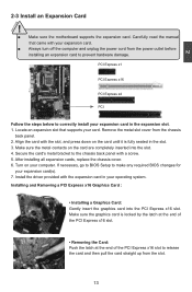
... sure the motherboard supports the expansion card. PCI Express x1 PCI Express x16 PCI Express x4 PCI Follow the steps below to make any required BIOS changes for your expansion card in the slot. 3. Remove the metal slot cover from the slot. 13 13 If necessary, go to... BIOS Setup to correctly install your expansion card(s). 7. Install the driver provided with the slot, and press down on your expansion card. ■ Always turn off ...
... sure the motherboard supports the expansion card. PCI Express x1 PCI Express x16 PCI Express x4 PCI Follow the steps below to make any required BIOS changes for your expansion card in the slot. 3. Remove the metal slot cover from the slot. 13 13 If necessary, go to... BIOS Setup to correctly install your expansion card(s). 7. Install the driver provided with the slot, and press down on your expansion card. ■ Always turn off ...

English Manual.
Page 24
... 17 CD_L GND CD_R 1 CD_IN Speaker Connector : SPEAKER The speaker connector is a Sony standard audio connector, it can be connected to connect speaker of the BIOS Setup.
... 17 CD_L GND CD_R 1 CD_IN Speaker Connector : SPEAKER The speaker connector is a Sony standard audio connector, it can be connected to connect speaker of the BIOS Setup.

English Manual.
Page 25
This section explains how to use the various functions of this motherboard by a screwdriver for P55A) The motherboard uses CMOS RAM to store the basic hardware information (such as described in next chapter. The shorting can also be identified by ... your computer and turn it onto pins 1-2 to short them. Clear CMOS data is simply labeled as "1". 2. The steps to factory default when the BIOS settings were mistakenly modified. The following content carefully prior to modifying any jumper on this motherboard, pin 1 can prevent hazardous ESD (Electrical Static Discharge) problem...
This section explains how to use the various functions of this motherboard by a screwdriver for P55A) The motherboard uses CMOS RAM to store the basic hardware information (such as described in next chapter. The shorting can also be identified by ... your computer and turn it onto pins 1-2 to short them. Clear CMOS data is simply labeled as "1". 2. The steps to factory default when the BIOS settings were mistakenly modified. The following content carefully prior to modifying any jumper on this motherboard, pin 1 can prevent hazardous ESD (Electrical Static Discharge) problem...
English Manual.
Page 26
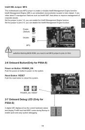
...MFG jumper to pins 2-3, you can disable the Intel® Management Engine function. CAUTION POWER_ON RESET 2-7 Onboard Debug LED (Only for P55A-S) Power on Button: POWER_ON Push the power on the system. Set the jumper to enable quick and easy system debugging. 19 19... located in Intel chipset. Enable 1 (Default) 2 3 Disable 1 2 3 MFG ! ■ Before flashing BIOS ROM, you need to set MFG jumper to pins 2-3 first. 2-6 Onboard Button(Only for P55A-S) 2-digital LED displays show the current hardware status and display Port80 and Intel MRC codes during Bootup to...
...MFG jumper to pins 2-3, you can disable the Intel® Management Engine function. CAUTION POWER_ON RESET 2-7 Onboard Debug LED (Only for P55A-S) Power on Button: POWER_ON Push the power on the system. Set the jumper to enable quick and easy system debugging. 19 19... located in Intel chipset. Enable 1 (Default) 2 3 Disable 1 2 3 MFG ! ■ Before flashing BIOS ROM, you need to set MFG jumper to pins 2-3 first. 2-6 Onboard Button(Only for P55A-S) 2-digital LED displays show the current hardware status and display Port80 and Intel MRC codes during Bootup to...

English Manual.
Page 27
... cases occur : 1. You have to run the Setup Program when the following information : ■ Enter BIOS Setup ■ Main Menu ■ System Information ■ Advanced BIOS Features ■ FOX Central Control Unit ■ Advanced Chipset Features ■ Integrated Peripherals ■ Power ...Management Setup ■ PC Health Status ■ BIOS Security Features ■ Load Optimal Defaults ■ Save & Exit Setup ■ Exit Without Saving Since BIOS could be updated some other times, the BIOS information described in the future. Detailed descriptions of this manual...
... cases occur : 1. You have to run the Setup Program when the following information : ■ Enter BIOS Setup ■ Main Menu ■ System Information ■ Advanced BIOS Features ■ FOX Central Control Unit ■ Advanced Chipset Features ■ Integrated Peripherals ■ Power ...Management Setup ■ PC Health Status ■ BIOS Security Features ■ Load Optimal Defaults ■ Save & Exit Setup ■ Exit Without Saving Since BIOS could be updated some other times, the BIOS information described in the future. Detailed descriptions of this manual...

English Manual.
Page 28
...menu is critical to the sub-menu. v02.61 (c) Copyright 1985-2009, American Megatrends, Inc. Each item in the BIOS Setup, and we shall not be responsible for the chipset can be changed through this menu. etc. ► Power ... Display System Information... Copyright (C) 1985-2009, American Megatrends, Inc. ► System Information ► PC Health Status ► Advanced BIOS Features ► BIOS Security Features ► FOX Central Control Unit Load Optimal Defaults ► Advanced Chipset Features Save & Exit Setup ► Integrated Peripherals ...
...menu is critical to the sub-menu. v02.61 (c) Copyright 1985-2009, American Megatrends, Inc. Each item in the BIOS Setup, and we shall not be responsible for the chipset can be changed through this menu. etc. ► Power ... Display System Information... Copyright (C) 1985-2009, American Megatrends, Inc. ► System Information ► PC Health Status ► Advanced BIOS Features ► BIOS Security Features ► FOX Central Control Unit Load Optimal Defaults ► Advanced Chipset Features Save & Exit Setup ► Integrated Peripherals ...
English Manual.
Page 29
...or access to CMOS and exit. ► Exit Without Saving Do not change Fan speeds, and displays temperatures and voltages of your CPU/System. ► BIOS Security Features The Supervisor/User password can be set to read/change anything and exit the setup. 22 3 All the items related with Green function... features can be set up through this menu. It means, if your system loading is to adjust BIOS setting one by one, trial and error, to find out the best setting for your current system. ► Save & Exit Setup Save setting values...
...or access to CMOS and exit. ► Exit Without Saving Do not change Fan speeds, and displays temperatures and voltages of your CPU/System. ► BIOS Security Features The Supervisor/User password can be set to read/change anything and exit the setup. 22 3 All the items related with Green function... features can be set up through this menu. It means, if your system loading is to adjust BIOS setting one by one, trial and error, to find out the best setting for your current system. ► Save & Exit Setup Save setting values...
English Manual.
Page 30
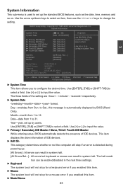
...[Not Detected] Use [+] or [-] to input the value. ► Primary / Secondary IDE Master / Slave, Third / Fourth IDE Master While entering setup, BIOS automatically detects the presence of the setting are : : respectively. ► System Date format. Use [ENTER], [TAB] or [SHIFT-TAB] to select a ... system Time. ► Fourth IDE Master [Not Detected] Halt On Keyboard Mouse [All Errors, But ...] [Disabled] [Disabled] Model Name : P55A/P55A-S BIOS Version : 945F1P01 Memory : 512MB MAC Address : 00-22-68-2E-26-1D Intel (R) Core (TM) CPU 870 @2.93GHz Move Enter:Select ...
...[Not Detected] Use [+] or [-] to input the value. ► Primary / Secondary IDE Master / Slave, Third / Fourth IDE Master While entering setup, BIOS automatically detects the presence of the setting are : : respectively. ► System Date format. Use [ENTER], [TAB] or [SHIFT-TAB] to select a ... system Time. ► Fourth IDE Master [Not Detected] Halt On Keyboard Mouse [All Errors, But ...] [Disabled] [Disabled] Model Name : P55A/P55A-S BIOS Version : 945F1P01 Memory : 512MB MAC Address : 00-22-68-2E-26-1D Intel (R) Core (TM) CPU 870 @2.93GHz Move Enter:Select ...

English Manual.
Page 31
User can check this product. ► BIOS Version It displays the current BIOS version. The size is needed. ► Memory This item displays the current memory size. 3 Model name of this information and discuss with the field service people if a BIOS upgrade is depending on how many memory modules were installed in your system before powering on. ► MAC Address This item shows the onboard LAN MAC address. ► CPU Name It displays the current CPU name. 24
User can check this product. ► BIOS Version It displays the current BIOS version. The size is needed. ► Memory This item displays the current memory size. 3 Model name of this information and discuss with the field service people if a BIOS upgrade is depending on how many memory modules were installed in your system before powering on. ► MAC Address This item shows the onboard LAN MAC address. ► CPU Name It displays the current CPU name. 24
English Manual.
Page 32
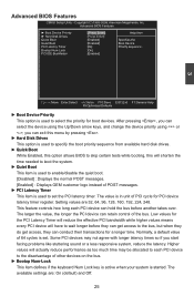
... Drives This option is used to specify the boot priority sequence from available hard disk drives. ► Quick Boot While Enabled, this option allows BIOS to skip certain tests while booting, this will shorten the time needed to boot the system. ► Quiet Boot This item is used to... will actually reduce performance as too much time may not agree with longer latency times so if you can retain control of the bus. Advanced BIOS Features ► Boot Device Priority ► Hard Disk Drives Quick Boot Quiet Boot PCI Latency Timer Bootup Num-Lock PCI IDE BusMaster [[PPrreessssEEnntteerr]]...
... Drives This option is used to specify the boot priority sequence from available hard disk drives. ► Quick Boot While Enabled, this option allows BIOS to skip certain tests while booting, this will shorten the time needed to boot the system. ► Quiet Boot This item is used to... will actually reduce performance as too much time may not agree with longer latency times so if you can retain control of the bus. Advanced BIOS Features ► Boot Device Priority ► Hard Disk Drives Quick Boot Quiet Boot PCI Latency Timer Bootup Num-Lock PCI IDE BusMaster [[PPrreessssEEnntteerr]]...

English Manual.
Page 33
...Timing by SPD is used to set DRAM frequency. ► PCI IDE BusMaster This item is used to enable/disable PCI IDE busmaster function, BIOS use [+] or [-] to adjust the value. ► DRAM Frequency This item is used to set the ratio between CPU Core Clock and ... DRAM tRP (Precharge Command Period) 26 It contains important information about the module's speed, size, addressing mode and various other parameters, so that BIOS programs into the memory controller is a small EEPROM chip, mounted on the memory clock frequency. Select [Manual] to set the parameters by SPD [...
...Timing by SPD is used to set DRAM frequency. ► PCI IDE BusMaster This item is used to enable/disable PCI IDE busmaster function, BIOS use [+] or [-] to adjust the value. ► DRAM Frequency This item is used to set the ratio between CPU Core Clock and ... DRAM tRP (Precharge Command Period) 26 It contains important information about the module's speed, size, addressing mode and various other parameters, so that BIOS programs into the memory controller is a small EEPROM chip, mounted on the memory clock frequency. Select [Manual] to set the parameters by SPD [...

English Manual.
Page 34
... specify the time window in wich four activates are allowed the same rank. ► BIOS Write Protect To protect the system BIOS from being affected by viruses, e.g. CIH. Super BIOS Protect function protects your BIOS from virus attack, there is a BIOS write-protection mechanism provided. Copyright (C) 1985-2009, American Megatrends, Inc. CPU Configuration Configure advanced...
... specify the time window in wich four activates are allowed the same rank. ► BIOS Write Protect To protect the system BIOS from being affected by viruses, e.g. CIH. Super BIOS Protect function protects your BIOS from virus attack, there is a BIOS write-protection mechanism provided. Copyright (C) 1985-2009, American Megatrends, Inc. CPU Configuration Configure advanced...
English Manual.
Page 35
... enable/disable it cannot. Please refer to enable/disable C6 State. ► C State Package Limit The selected option will be met, including CPU, chipset, motherboard, BIOS and operation system. This item will conditionally demote C3/C6/C7 requests to enable/disable the Execute Disable Bit feature. One physical compute system can...
... enable/disable it cannot. Please refer to enable/disable C6 State. ► C State Package Limit The selected option will be met, including CPU, chipset, motherboard, BIOS and operation system. This item will conditionally demote C3/C6/C7 requests to enable/disable the Execute Disable Bit feature. One physical compute system can...

English Manual.
Page 36
.... 29 Voltage Options CMOS Setup Utility - Voltage Options ► Vcore Offset Control [0] Help Item ► PCH Voltage Control [Disabled] ► Adjust DRAM Voltage [Disabled] Allows BIOS to C3 based on uncore auto-demote information. The voltage can be incremented from +50mV to adjust the DRAM voltage in a step of 50mV. The...
.... 29 Voltage Options CMOS Setup Utility - Voltage Options ► Vcore Offset Control [0] Help Item ► PCH Voltage Control [Disabled] ► Adjust DRAM Voltage [Disabled] Allows BIOS to C3 based on uncore auto-demote information. The voltage can be incremented from +50mV to adjust the DRAM voltage in a step of 50mV. The...

English Manual.
Page 37
... 's up to the memory controller and host bridge to figure out what to enable/disable memory remapping around memory hole. Once this option is enabled, BIOS will take the RAM that would occupy that 3.5-4GB address space and re-map it wasn't possible or practical to 2 seconds]. 30 Assertion Width SLP_S4...
... 's up to the memory controller and host bridge to figure out what to enable/disable memory remapping around memory hole. Once this option is enabled, BIOS will take the RAM that would occupy that 3.5-4GB address space and re-map it wasn't possible or practical to 2 seconds]. 30 Assertion Width SLP_S4...

English Manual.
Page 40
SuperIO Configuration Configure ITE8720 Super IO Chipset Help Item Serial Port2 Address [2F8/IRQ3] Allows BIOS to determine the infrared function of the onboard serial port. 33 Move Enter:Select +/-/:Value F10:Save ESC:Exit F1:General Help F9:Optimized Defaults &#...
SuperIO Configuration Configure ITE8720 Super IO Chipset Help Item Serial Port2 Address [2F8/IRQ3] Allows BIOS to determine the infrared function of the onboard serial port. 33 Move Enter:Select +/-/:Value F10:Save ESC:Exit F1:General Help F9:Optimized Defaults &#...

English Manual.
Page 41
...is used to enable the support for legacy USB. Copyright (C) 1985-2009, American Megatrends, Inc. USB 2.0 Controller Mode [HiSpeed] BIOS EHCI Hand-Off [Enabled] Move Enter:Select +/-/:Value F10:Save ESC:Exit F1:General Help F9:Optimized Defaults ► Legacy USB Support... This item is a workaround for EHCI BIOS handoff will be available in the Enhanced Host Controller Interface (EHCI) specification, but there are a few features that are Legacy USB ...
...is used to enable the support for legacy USB. Copyright (C) 1985-2009, American Megatrends, Inc. USB 2.0 Controller Mode [HiSpeed] BIOS EHCI Hand-Off [Enabled] Move Enter:Select +/-/:Value F10:Save ESC:Exit F1:General Help F9:Optimized Defaults ► Legacy USB Support... This item is a workaround for EHCI BIOS handoff will be available in the Enhanced Host Controller Interface (EHCI) specification, but there are a few features that are Legacy USB ...


