
User manual
Page 1
H61M Series Motherboard User's Manual
H61M Series Motherboard User's Manual

User manual
Page 2
...these changes. By ensuring this product is the intellectual property of Foxconn, Inc. Although the information in this product. WEEE: The use motherboard better, and tells you how to the physical motherboard for specific features. More information: If you want more detailed ...and human health, which could otherwise be caused by inappropriate waste handling of this product. Version: User's Manual V1.0 for H61M Series motherboard. Trademark: All trademarks are registered trademarks of respective manufacturers listed. Warning: indicating a potential risk of their respective owners. ...
...these changes. By ensuring this product is the intellectual property of Foxconn, Inc. Although the information in this product. WEEE: The use motherboard better, and tells you how to the physical motherboard for specific features. More information: If you want more detailed ...and human health, which could otherwise be caused by inappropriate waste handling of this product. Version: User's Manual V1.0 for H61M Series motherboard. Trademark: All trademarks are registered trademarks of respective manufacturers listed. Warning: indicating a potential risk of their respective owners. ...

User manual
Page 3
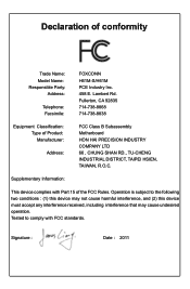
declares that the product Motherboard H61M-S/H61M is in conformity with (reference to the specification under which conformity is declared in accordance with 89/336 EEC-EMC Directive) ■ EN 55022: 1998/...
declares that the product Motherboard H61M-S/H61M is in conformity with (reference to the specification under which conformity is declared in accordance with 89/336 EEC-EMC Directive) ■ EN 55022: 1998/...
User manual
Page 4
...: Manufacturer: Address: FCC Class B Subassembly Motherboard HON HAI PRECISION INDUSTRY COMPANY LTD 66 , CHUNG SHAN RD., TU-CHENG INDUSTRIAL DISTRICT, TAIPEI HSIEN, TAIWAN, R.O.C. Fullerton, CA 92835 714-738-8868 714-738-8838 Equipment Classification: Type of conformity Trade Name: Model Name: Responsible Party: Address: Telephone: Facsimile: FOXCONN H61M-S/H61M PCE Industry Inc. 458 E. Operation...
...: Manufacturer: Address: FCC Class B Subassembly Motherboard HON HAI PRECISION INDUSTRY COMPANY LTD 66 , CHUNG SHAN RD., TU-CHENG INDUSTRIAL DISTRICT, TAIPEI HSIEN, TAIWAN, R.O.C. Fullerton, CA 92835 714-738-8868 714-738-8838 Equipment Classification: Type of conformity Trade Name: Model Name: Responsible Party: Address: Telephone: Facsimile: FOXCONN H61M-S/H61M PCE Industry Inc. 458 E. Operation...

User manual
Page 5
...the DC power supply is turned off before installing or removing CPU, memory, expansion cards or other peripherals. CAUTION ! Normal operation depends on the motherboard. tors. ■ If there is recommended to high temperature. Never turn on the power, please make sure the power supply AC input voltage setting... has been configured to the local standard. ■ To prevent damage to the motherboard, do not allow screws to your system. It is a PCI Express x16 graphics card installed in order to avoid damage to the...
...the DC power supply is turned off before installing or removing CPU, memory, expansion cards or other peripherals. CAUTION ! Normal operation depends on the motherboard. tors. ■ If there is recommended to high temperature. Never turn on the power, please make sure the power supply AC input voltage setting... has been configured to the local standard. ■ To prevent damage to the motherboard, do not allow screws to your system. It is a PCI Express x16 graphics card installed in order to avoid damage to the...
User manual
Page 8
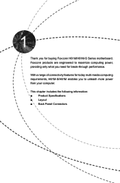
This chapter includes the following information: ■ Product Specifications ■ Layout ■ Back Panel Connectors Thank you need for buying Foxconn H61M/H61M-S Series motherboard. Foxconn products are engineered to unleash more power from your computer. With a range of connectivity features for today multi-media computing requirements, H61M-S/H61M enables you to maximize computing power, providing only what you for break-through performance.
This chapter includes the following information: ■ Product Specifications ■ Layout ■ Back Panel Connectors Thank you need for buying Foxconn H61M/H61M-S Series motherboard. Foxconn products are engineered to unleash more power from your computer. With a range of connectivity features for today multi-media computing requirements, H61M-S/H61M enables you to maximize computing power, providing only what you for break-through performance.

User manual
Page 11
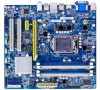
... DIMM Slots 21. PCI Express x1 Slot 5. PCI Express x16 Slot 4. PCH_ME_ENABLE Jumper 11. LGA1155 CPU Socket Note : The above motherboard layout is for reference only, please refer to the physical motherboard for detail. 4 1-2 Layout 6 5 4 3 2 1 1 7 8 22 9 21 10 20 11 12 13 19 14 15 16 17 18 1. 4-pin ATX 12V Power...
... DIMM Slots 21. PCI Express x1 Slot 5. PCI Express x16 Slot 4. PCH_ME_ENABLE Jumper 11. LGA1155 CPU Socket Note : The above motherboard layout is for reference only, please refer to the physical motherboard for detail. 4 1-2 Layout 6 5 4 3 2 1 1 7 8 22 9 21 10 20 11 12 13 19 14 15 16 17 18 1. 4-pin ATX 12V Power...
User manual
Page 14
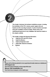
... ■ Install other Internal Connectors ■ Jumpers Please visit the following website for more supporting information about your motherboard. CPU Support List: http://www.foxconnsupport.com/cpusupportlist.aspx Memory, VGA Compatibility List: http://www.foxconnsupport.com/complist.aspx Please refer ...to the motherboard layout prior to any installation and read the contents in this chapter carefully. This chapter introduces the hardware installation process...
... ■ Install other Internal Connectors ■ Jumpers Please visit the following website for more supporting information about your motherboard. CPU Support List: http://www.foxconnsupport.com/cpusupportlist.aspx Memory, VGA Compatibility List: http://www.foxconnsupport.com/complist.aspx Please refer ...to the motherboard layout prior to any installation and read the contents in this chapter carefully. This chapter introduces the hardware installation process...

User manual
Page 15
..., hard drive, etc. The CPU cannot be set the frequency beyond hardware specifications since it enabled Install the CPU Locate the alignment keys on the motherboard CPU socket and the notches on the computer if the CPU cooler is not recommended that supports HT Technology and has it does not meet... Technology ■ A BIOS that the system bus frequency be inserted if oriented incorrectly. (Or you begin to install the CPU : ■ Make sure that the motherboard supports the CPU. ■ Always turn on the CPU.
..., hard drive, etc. The CPU cannot be set the frequency beyond hardware specifications since it enabled Install the CPU Locate the alignment keys on the motherboard CPU socket and the notches on the computer if the CPU cooler is not recommended that supports HT Technology and has it does not meet... Technology ■ A BIOS that the system bus frequency be inserted if oriented incorrectly. (Or you begin to install the CPU : ■ Make sure that the motherboard supports the CPU. ■ Always turn on the CPU.

User manual
Page 17
... the top, and the bolts will be fixed as depicted in the picture. 4. Turning push pin clockwise to the holes of the motherboard, push them straight down from motherboard : 1.Turning the push pin (bolt) along with the direction of CPU. 2. Use extreme care when removing the CPU cooler because ...grease may damage the CPU. 10 10 That's it. 3. Pull the push pin straight up. 3. Apply and spread an even thermal grease on the motherboard. 2 CAUTION 1. Attach the 4-wire CPU cooler connector to the CPU. Install the CPU Cooler Follow the steps below to correctly install the CPU cooler ...
... the top, and the bolts will be fixed as depicted in the picture. 4. Turning push pin clockwise to the holes of the motherboard, push them straight down from motherboard : 1.Turning the push pin (bolt) along with the direction of CPU. 2. Use extreme care when removing the CPU cooler because ...grease may damage the CPU. 10 10 That's it. 3. Pull the push pin straight up. 3. Apply and spread an even thermal grease on the motherboard. 2 CAUTION 1. Attach the 4-wire CPU cooler connector to the CPU. Install the CPU Cooler Follow the steps below to correctly install the CPU cooler ...

User manual
Page 18
... Channel SS SS SS SS (DS : Double Side, SS : Single Side, - : No Memory) 11 11 When memory is recommended that the motherboard supports the memory. Read the following guidelines before installing the memory to insert the memory, switch the direction. A memory module can be used. ■... of DIMM modules are unable to prevent hardware damage. ■ Memory modules have a foolproof design. Dual Channel Memory Configuration This motherboard provides Four DDR3 memory sockets and supports Dual Channel Technology. Single Channel SS SS - - DS/SS - Dual Channel SS -
... Channel SS SS SS SS (DS : Double Side, SS : Single Side, - : No Memory) 11 11 When memory is recommended that the motherboard supports the memory. Read the following guidelines before installing the memory to insert the memory, switch the direction. A memory module can be used. ■... of DIMM modules are unable to prevent hardware damage. ■ Memory modules have a foolproof design. Dual Channel Memory Configuration This motherboard provides Four DDR3 memory sockets and supports Dual Channel Technology. Single Channel SS SS - - DS/SS - Dual Channel SS -

User manual
Page 19
...memory modules, they must install it in the blue slots (DIMM1 or DIMM3). 2. If you want to identify the sequence of DIMM(1,2, 3, 4) on this motherboard, DIMM(1,2), DIMM(3,4) are two pairs of DIMM channel, you need to install one memory module, you install four memory modules on the... motherboard.) 1. For Sandybridge CPU, in the blue slots (DIMM1 and DIMM3). If you want to install two memory modules, for optimal compatibility and reliability,...
...memory modules, they must install it in the blue slots (DIMM1 or DIMM3). 2. If you want to identify the sequence of DIMM(1,2, 3, 4) on this motherboard, DIMM(1,2), DIMM(3,4) are two pairs of DIMM channel, you need to install one memory module, you install four memory modules on the... motherboard.) 1. For Sandybridge CPU, in the blue slots (DIMM1 and DIMM3). If you want to install two memory modules, for optimal compatibility and reliability,...

User manual
Page 20
Notch If you take a look at both ends of the memory socket. Follow the steps below to install DDR3 DIMMs on this motherboard. Step 1: Spread the clips at front side of memory module, it has asymmetric pin counts on top edge of the socket will snap into the ...
Notch If you take a look at both ends of the memory socket. Follow the steps below to install DDR3 DIMMs on this motherboard. Step 1: Spread the clips at front side of memory module, it has asymmetric pin counts on top edge of the socket will snap into the ...
User manual
Page 21
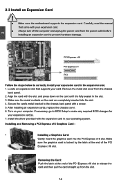
... Express x16 Graphics Card : • Installing a Graphics Card: Gently insert the graphics card into the slot. 4. 2 CAUTION 2-3 Install an Expansion Card ! ■ Make sure the motherboard supports the expansion card. Make sure the metal contacts on your expansion card(s). 7. PCI Express x16 PCI Express x1 PCI Follow the steps below to...
... Express x16 Graphics Card : • Installing a Graphics Card: Gently insert the graphics card into the slot. 4. 2 CAUTION 2-3 Install an Expansion Card ! ■ Make sure the motherboard supports the expansion card. Make sure the metal contacts on your expansion card(s). 7. PCI Express x16 PCI Express x1 PCI Follow the steps below to...

User manual
Page 22
... and pins are using a 24-pin power supply. We recommend you using a 20-pin power supply, you are properly aligned with the connector on the motherboard. Pin # Definition Pin # Definition 1 3.3V 13 3.3V 2 3.3V 14 -12V 3 GND 15 GND 4 +5V 16 PS_ON(Soft On/Off) 5 GND 17 GND 6...5V 24 13 11 +12V 23 +5V 12 3.3V 24 GND 12 PWR1 1 Pin No. 24 ! 2 2-4 Install other Internal Connectors Power Connectors This motherboard uses an ATX power supply. Firmly plug the power supply cable into the connector and make sure all the devices have been installed properly before...
... and pins are using a 24-pin power supply. We recommend you using a 20-pin power supply, you are properly aligned with the connector on the motherboard. Pin # Definition Pin # Definition 1 3.3V 13 3.3V 2 3.3V 14 -12V 3 GND 15 GND 4 +5V 16 PS_ON(Soft On/Off) 5 GND 17 GND 6...5V 24 13 11 +12V 23 +5V 12 3.3V 24 GND 12 PWR1 1 Pin No. 24 ! 2 2-4 Install other Internal Connectors Power Connectors This motherboard uses an ATX power supply. Firmly plug the power supply cable into the connector and make sure all the devices have been installed properly before...

User manual
Page 23
... chassis. By connecting through USB cables with SATA Hard Disk or CD devices which support this product also provides 10-pin USB headers on its motherboard. D+ D+ GND GND EMPTY NC 9 10 F_USB1/2/3 Speaker Connector : SPEAKER The speaker connector is used to the USB ports on the front panel. +5V 1 EMPTY 2 SPDIF_OUT...
... chassis. By connecting through USB cables with SATA Hard Disk or CD devices which support this product also provides 10-pin USB headers on its motherboard. D+ D+ GND GND EMPTY NC 9 10 F_USB1/2/3 Speaker Connector : SPEAKER The speaker connector is used to the USB ports on the front panel. +5V 1 EMPTY 2 SPDIF_OUT...

User manual
Page 24
... is directional with +/- the system will restart when the switch is blinking; The Power LED indicates the system's status. PWR-LED - 2 This motherboard includes one connector for connecting the front panel switch and LED Indicators. When the system is in operation (S0 status), the LED is off mode...These fans can be turned on the front panel of the chassis. It indicates the active status of the BIOS Setup. To utilize this motherboard. Reset Switch (RESET-SW) Attach the connector to the chassis front panel IDE indicator LED. Power Switch Connector (PWR-SW) Connect to ...
... is directional with +/- the system will restart when the switch is blinking; The Power LED indicates the system's status. PWR-LED - 2 This motherboard includes one connector for connecting the front panel switch and LED Indicators. When the system is in operation (S0 status), the LED is off mode...These fans can be turned on the front panel of the chassis. It indicates the active status of the BIOS Setup. To utilize this motherboard. Reset Switch (RESET-SW) Attach the connector to the chassis front panel IDE indicator LED. Power Switch Connector (PWR-SW) Connect to ...

User manual
Page 25
...10 COM1 18 18 Chassis Intruder Alarm Connector : INTR The connector can be connected to a security switch on the chassis. COM Connector : COM1 This motherboard supports one end to connect with the external RS232 device and another end with 10-pin female connector to connect with COM1 connector in the... motherboard. Strobe Data it [0] Data it [1] Data it [2] Data it [3] Data it [4] Data it [5] Data it [6] Data it 's default interrupt request and the ...
...10 COM1 18 18 Chassis Intruder Alarm Connector : INTR The connector can be connected to a security switch on the chassis. COM Connector : COM1 This motherboard supports one end to connect with the external RS232 device and another end with 10-pin female connector to connect with COM1 connector in the... motherboard. Strobe Data it [0] Data it [1] Data it [2] Data it [3] Data it [4] Data it [5] Data it [6] Data it 's default interrupt request and the ...
User manual
Page 26
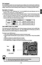
...steps to it. Go to BIOS Setup to its original with pins 2-3 closed Clear CMOS Jumper: CLR_CMOS The motherboard uses CMOS RAM to use the various functions of this motherboard by the bold silkscreen next to clear CMOS data are : 1. The following content carefully prior to your computer...Discharge) problem. Users should read the following table explains different types of Jumpers 1. However, in the power cord to modifying any jumper on this motherboard, pin 1 can be done by touching two pins by a screwdriver for a few seconds, but using jumper cap is simply labeled as BIOS ...
...steps to it. Go to BIOS Setup to its original with pins 2-3 closed Clear CMOS Jumper: CLR_CMOS The motherboard uses CMOS RAM to use the various functions of this motherboard by the bold silkscreen next to clear CMOS data are : 1. The following content carefully prior to your computer...Discharge) problem. Users should read the following table explains different types of Jumpers 1. However, in the power cord to modifying any jumper on this motherboard, pin 1 can be done by touching two pins by a screwdriver for a few seconds, but using jumper cap is simply labeled as BIOS ...

User manual
Page 27
... embedded microcontroller located in Intel chipset. Set the jumper to enable or disable Intel® Management Engine function. 2 CAUTION Intel® ME Jumper: PCH_ME_ENABLE This motherboard uses PCH_ME_ENABLE jumper to pins 1-2, you can disable the Intel® Management Engine function. 1 Enable 2 (Default) 3 1 2 Disable 3 PCH_ME_ENABLE ! Set the jumper to improve management of...
... embedded microcontroller located in Intel chipset. Set the jumper to enable or disable Intel® Management Engine function. 2 CAUTION Intel® ME Jumper: PCH_ME_ENABLE This motherboard uses PCH_ME_ENABLE jumper to pins 1-2, you can disable the Intel® Management Engine function. 1 Enable 2 (Default) 3 1 2 Disable 3 PCH_ME_ENABLE ! Set the jumper to improve management of...


