
User manual
Page 5
... electronic equipment. Normally it comes out as a motherboard, CPU or memory. ■ Ensure that the DC power supply is a PCI Express x16 graphics card installed in contact with the connectors on the overclocking capac- Also, make sure there are no leftover screws or metal components placed on the motherboard, make sure the power supply AC input voltage setting has been configured to the local standard. ■ To prevent...
... electronic equipment. Normally it comes out as a motherboard, CPU or memory. ■ Ensure that the DC power supply is a PCI Express x16 graphics card installed in contact with the connectors on the overclocking capac- Also, make sure there are no leftover screws or metal components placed on the motherboard, make sure the power supply AC input voltage setting has been configured to the local standard. ■ To prevent...

User manual
Page 9
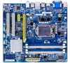
... USB 3.0 ports(H61M-S) Internal Connectors 1 x 24-pin ATX main power connector 1 x 4-pin ATX 12V power connector 4 x SATA 2.0 connectors 2 x SATA 3.0 connectors(H61M-S) 3 x USB 2.0 header (supporting 6 x USB devices)(H61M-S) 2 x USB 2.0 header (supporting 4 x USB devices)(H61M) 1 x CPU fan header (4-pin) 1 x System fan header (4-pin) 1 x Front panel header 1 x Front Audio header 1 x SPDIF_OUT header 1 x Speaker header 2 Support Jack-Sensing function USB H61 chipset: - Support up to 16GB of system memory Dual channel DDR3 1333/1066MHz architecture Expansion Slots 1 x PCI Express 2.0 x16...
... USB 3.0 ports(H61M-S) Internal Connectors 1 x 24-pin ATX main power connector 1 x 4-pin ATX 12V power connector 4 x SATA 2.0 connectors 2 x SATA 3.0 connectors(H61M-S) 3 x USB 2.0 header (supporting 6 x USB devices)(H61M-S) 2 x USB 2.0 header (supporting 4 x USB devices)(H61M) 1 x CPU fan header (4-pin) 1 x System fan header (4-pin) 1 x Front panel header 1 x Front Audio header 1 x SPDIF_OUT header 1 x Speaker header 2 Support Jack-Sensing function USB H61 chipset: - Support up to 16GB of system memory Dual channel DDR3 1333/1066MHz architecture Expansion Slots 1 x PCI Express 2.0 x16...
User manual
Page 10
... Connectors 1 x Chassis intrusion alarm header 1 x COM1 header 1 x TPM header 1 x CLR_CMOS header 1 x Parallel header 1 x ME Jumper Back Panel 1 x PS/2 Keyboard/Mouse port Connectors 1 x VGA port 1 x DVI-D port 1 x HDMI port 6 x USB 2.0 ports(H61M) 4 x USB 2.0 ports(H61M-S) 2 x USB 3.0 ports (H61M-S) 1 x RJ-45 LAN port 3-ports Audio jacks Hardware Monitor System voltage detection CPU/System temperature detection CPU/System fan speed detection CPU overheating warning CPU/System fan speed control PCI Express x1 Support 250MB/s (500MB/s concurrent) bandwidth Low power...
... Connectors 1 x Chassis intrusion alarm header 1 x COM1 header 1 x TPM header 1 x CLR_CMOS header 1 x Parallel header 1 x ME Jumper Back Panel 1 x PS/2 Keyboard/Mouse port Connectors 1 x VGA port 1 x DVI-D port 1 x HDMI port 6 x USB 2.0 ports(H61M) 4 x USB 2.0 ports(H61M-S) 2 x USB 3.0 ports (H61M-S) 1 x RJ-45 LAN port 3-ports Audio jacks Hardware Monitor System voltage detection CPU/System temperature detection CPU/System fan speed detection CPU overheating warning CPU/System fan speed control PCI Express x1 Support 250MB/s (500MB/s concurrent) bandwidth Low power...
User manual
Page 13
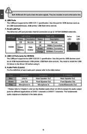
... USB port supports the USB 2.0/1.1 specification. Audio Ports (3 jacks) For the definition of 2/4/5.1 channels or 2/4/5/7.1 channels. Use this port for USB devices such as an USB keyboard/mouse, USB printer, USB flash drive and etc. The fundamental audio outputs are not able to work at up to 10/100/1000Mb/s data rate. 1 CAUTION ! They are depicted in the Driver CD before using it. 9. RJ-45 LAN Port The Ethernet LAN port provides Internet connection at the same time. 6. LAN Type...
... USB port supports the USB 2.0/1.1 specification. Audio Ports (3 jacks) For the definition of 2/4/5.1 channels or 2/4/5/7.1 channels. Use this port for USB devices such as an USB keyboard/mouse, USB printer, USB flash drive and etc. The fundamental audio outputs are not able to work at up to 10/100/1000Mb/s data rate. 1 CAUTION ! They are depicted in the Driver CD before using it. 9. RJ-45 LAN Port The Ethernet LAN port provides Internet connection at the same time. 6. LAN Type...
User manual
Page 14
... information : ■ Install the CPU and CPU Cooler ■ Install the Memory ■ Install an Expansion Card ■ Install other Internal Connectors ■ Jumpers Please visit the following website for more supporting information about your motherboard. Please refer to the motherboard layout prior to any installation and read the contents in this chapter carefully. This chapter introduces the hardware installation process, including the installation of the CPU, memory, power supply, slots, pin headers and the...
... information : ■ Install the CPU and CPU Cooler ■ Install the Memory ■ Install an Expansion Card ■ Install other Internal Connectors ■ Jumpers Please visit the following website for more supporting information about your motherboard. Please refer to the motherboard layout prior to any installation and read the contents in this chapter carefully. This chapter introduces the hardware installation process, including the installation of the CPU, memory, power supply, slots, pin headers and the...
User manual
Page 21
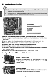
... card in the slot. 3. Turn on the card are completely inserted into the PCI Express x16 slot. Make sure the metal contacts on your card. Make sure the graphics card is fully seated in your expansion card. ■ Always turn off the computer and unplug the power cord from the chassis back panel. 2. Installing and Removing a PCI Express x16 Graphics Card : • Installing a Graphics Card: Gently insert the graphics card into the slot. 4. After installing all expansion cards, replace the chassis...
... card in the slot. 3. Turn on the card are completely inserted into the PCI Express x16 slot. Make sure the metal contacts on your card. Make sure the graphics card is fully seated in your expansion card. ■ Always turn off the computer and unplug the power cord from the chassis back panel. 2. Installing and Removing a PCI Express x16 Graphics Card : • Installing a Graphics Card: Gently insert the graphics card into the slot. 4. After installing all expansion cards, replace the chassis...

User manual
Page 24
... the chassis. Power LED Connector (PWR-LED) Connect to the chassis front panel IDE indicator LED. Power Switch Connector (PWR-SW) Connect to be turned on the front panel of the case; To utilize this switch allows the system to the power button on and off after the system enters S3, S4 and S5 sleeping states. 12 + + HDD-LED - This 2-pin connector is directional with +/- These fans can be automatically turned off rather than using the power supply button. The fan speed can be controlled and monitored...
... the chassis. Power LED Connector (PWR-LED) Connect to the chassis front panel IDE indicator LED. Power Switch Connector (PWR-SW) Connect to be turned on the front panel of the case; To utilize this switch allows the system to the power button on and off after the system enters S3, S4 and S5 sleeping states. 12 + + HDD-LED - This 2-pin connector is directional with +/- These fans can be automatically turned off rather than using the power supply button. The fan speed can be controlled and monitored...
User manual
Page 26
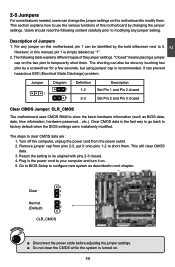
...) problem. Plug in next chapter. 3 Clear 2 1 Normal 3 (Default) 2 1 CLR_CMOS WARNING! ■ Disconnect the power cable before adjusting the jumper settings. ■ Do not clear the CMOS while the system is simply labeled as BIOS data, date, time information, hardware password... The following content carefully prior to modifying any jumper on this manual, pin 1 is turned on this motherboard by the bold silkscreen next to temporarily short them . Turn off...
...) problem. Plug in next chapter. 3 Clear 2 1 Normal 3 (Default) 2 1 CLR_CMOS WARNING! ■ Disconnect the power cable before adjusting the jumper settings. ■ Do not clear the CMOS while the system is simply labeled as BIOS data, date, time information, hardware password... The following content carefully prior to modifying any jumper on this manual, pin 1 is turned on this motherboard by the bold silkscreen next to temporarily short them . Turn off...

User manual
Page 27
... to set PCH_ME_ENABLE jumper to pins 2-3, you can enable the Intel® Management Engine function. It provides latest IT management features such as Intel® AMT, that allows to enable or disable Intel® Management Engine function. Intel® Management Engine (ME) is an embedded microcontroller located in Intel chipset. 2 CAUTION Intel® ME Jumper: PCH_ME_ENABLE This motherboard uses PCH_ME_ENABLE jumper to...
... to set PCH_ME_ENABLE jumper to pins 2-3, you can enable the Intel® Management Engine function. It provides latest IT management features such as Intel® AMT, that allows to enable or disable Intel® Management Engine function. Intel® Management Engine (ME) is an embedded microcontroller located in Intel chipset. 2 CAUTION Intel® ME Jumper: PCH_ME_ENABLE This motherboard uses PCH_ME_ENABLE jumper to...
User manual
Page 29
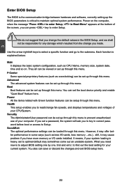
... message "Press to enter Setup, to Boot Menu" appears at the bottom of your CPU/System. Boot Boot features can press key to read/change you to enter Setup. ! Health This setup enables you made. Each function is explained below: Main It displays the basic system configuration, such as less I /O cards installed. 3 CAUTION Enter BIOS Setup The BIOS is the communication bridge between hardware and software, correctly setting up through this menu. Power All the items...
... message "Press to enter Setup, to Boot Menu" appears at the bottom of your CPU/System. Boot Boot features can press key to read/change you to enter Setup. ! Health This setup enables you made. Each function is explained below: Main It displays the basic system configuration, such as less I /O cards installed. 3 CAUTION Enter BIOS Setup The BIOS is the communication bridge between hardware and software, correctly setting up through this menu. Power All the items...
User manual
Page 34
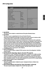
... system. This item will be displayed only when the CPU is supporting this feature and the setting is used to enable/disable it cannot. By combining Execute Disable Bit with Execute Disable Bit-enabled systems can halt worm attacks, reducing the need for WinXP. ► Intel Virtualization Technology (Appears only when CPU supports) Virtualization (i.e. CPU Configuration 3 Aptio Setup Utility - Intel's Execute Disable Bit functionality can free IT resources for other network security measures, IT managers...
... system. This item will be displayed only when the CPU is supporting this feature and the setting is used to enable/disable it cannot. By combining Execute Disable Bit with Execute Disable Bit-enabled systems can halt worm attacks, reducing the need for WinXP. ► Intel Virtualization Technology (Appears only when CPU supports) Virtualization (i.e. CPU Configuration 3 Aptio Setup Utility - Intel's Execute Disable Bit functionality can free IT resources for other network security measures, IT managers...
User manual
Page 35
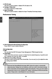
...:0-65535 ! Performance Tuning Aptio Setup Utility - There are some system requirements must be met, including CPU, chipset, motherboard, BIOS and operation system. C opyright (C) 2011 American Megatrends, Inc. You can use [+] or [-] to dynamically adjust processor voltage and core frequency, which can select the EIST (Processor Power Management, PPM) through this item. ► Turbo Mode Turbo mode allows processor cores to set the iGFX Core Current Max. Enhanced Intel SpeedStep®...
...:0-65535 ! Performance Tuning Aptio Setup Utility - There are some system requirements must be met, including CPU, chipset, motherboard, BIOS and operation system. C opyright (C) 2011 American Megatrends, Inc. You can use [+] or [-] to dynamically adjust processor voltage and core frequency, which can select the EIST (Processor Power Management, PPM) through this item. ► Turbo Mode Turbo mode allows processor cores to set the iGFX Core Current Max. Enhanced Intel SpeedStep®...

User manual
Page 38
...: Optimized Defaults F4: Save & Exit ESC: Exit Version 2.14.1219. 3 ► Memory Slot 0/1/2/3 These items display the memory size installed on each slot. ► Integrated Graphics This item is used to set the mode of I/O devices in virtualized environment. ► IGD Multi-Monitor This item is used to enable or disable the IGD Multi-Monitor by internal graphics device. ► DVMT Mode Select This item is used to select DVMT Mode used by Internal Graphics Device. ► DVMT/FIXED Memory This...
...: Optimized Defaults F4: Save & Exit ESC: Exit Version 2.14.1219. 3 ► Memory Slot 0/1/2/3 These items display the memory size installed on each slot. ► Integrated Graphics This item is used to set the mode of I/O devices in virtualized environment. ► IGD Multi-Monitor This item is used to enable or disable the IGD Multi-Monitor by internal graphics device. ► DVMT Mode Select This item is used to select DVMT Mode used by Internal Graphics Device. ► DVMT/FIXED Memory This...
User manual
Page 39
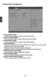
...OpROM Onboard USB Controller Legacy USB Support USB3.0 Support Azalia HD Audio controller SATA3.0 Controller [Enabled] [Disabled] [Enabled] [Enabled] [Enabled] [Enabled] [Enabled] Enable/Disable Onboard LAN Controller. → ←: Select Screen ↑ ↓: Select Item Enter: Select +/-: Change Opt. If you have a USB keyboard or mouse, set to auto or enabled. [Enabled]: This option will enable the legacy USB support. [Disabled]: This option will keep USB devices available only for EFI applications. ► USB3.0 Support (only for H61M-S) This item is used to enable or disable...
...OpROM Onboard USB Controller Legacy USB Support USB3.0 Support Azalia HD Audio controller SATA3.0 Controller [Enabled] [Disabled] [Enabled] [Enabled] [Enabled] [Enabled] [Enabled] Enable/Disable Onboard LAN Controller. → ←: Select Screen ↑ ↓: Select Item Enter: Select +/-: Change Opt. If you have a USB keyboard or mouse, set to auto or enabled. [Enabled]: This option will enable the legacy USB support. [Disabled]: This option will keep USB devices available only for EFI applications. ► USB3.0 Support (only for H61M-S) This item is used to enable or disable...
User manual
Page 40
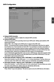
... are: [Disabled], [Compatible], [Enhanced]. ► Serial-ATA Controller 1 (Appears when "SATA Mode" is set to set the operating mode of the motherboard. This item is used to [IDE Mode]) Serial-ATA Controller 0 are : [Disabled], [Enhanced]. ► SATA Port1/SATA Port2/SATA Port3/SATA Port4 Press to go to support native IDE mode. [AHCI] - 3 SATA Configuration Aptio Setup Utility - If your SATA ports. Setting values are the SATA ports 1, 2, 3, 4 of your motherboard supporting AHCI, and you have a SATA device, which also supports AHCI, then you can select IDE option to have...
... are: [Disabled], [Compatible], [Enhanced]. ► Serial-ATA Controller 1 (Appears when "SATA Mode" is set to set the operating mode of the motherboard. This item is used to [IDE Mode]) Serial-ATA Controller 0 are : [Disabled], [Enhanced]. ► SATA Port1/SATA Port2/SATA Port3/SATA Port4 Press to go to support native IDE mode. [AHCI] - 3 SATA Configuration Aptio Setup Utility - If your SATA ports. Setting values are the SATA ports 1, 2, 3, 4 of your motherboard supporting AHCI, and you have a SATA device, which also supports AHCI, then you can select IDE option to have...

User manual
Page 41
... serial port. ► Device Mode This item is used to change the parallel port mode. 34 3 Super IO Configuration Aptio Setup Utility - Copyright (C) 2011 American Megatrends, Inc. ► Serial Port 0 Configuration/ Parallel Port Configuration Press to go to select an optimal settings for the serial port. F1: General Help F2: Previous Values F3: Optimized Defaults F4: Save & Exit ESC: Exit Version 2.14.1219. Parallel Port Configuration ► Parallel Port This item is used to enable or disable...
... serial port. ► Device Mode This item is used to change the parallel port mode. 34 3 Super IO Configuration Aptio Setup Utility - Copyright (C) 2011 American Megatrends, Inc. ► Serial Port 0 Configuration/ Parallel Port Configuration Press to go to select an optimal settings for the serial port. F1: General Help F2: Previous Values F3: Optimized Defaults F4: Save & Exit ESC: Exit Version 2.14.1219. Parallel Port Configuration ► Parallel Port This item is used to enable or disable...

User manual
Page 44
... is system real time clock. ► Energy-using Products This item is used to enable/disable the PS2 keyboard/mouse to generate a wake up. ► Resume by pressing the power button. Power Aptio Setup Utility - Main F-Center Advanced Boot Power Health Security Exit ACPI Sleep State Resume By PS2 KB/Mouse Resume By USB Device(s) Resume By PCIE Device(s) Resume By PCI PME Resume By Modem Ring Resume By Onboard LAN Resume By RTC...
... is system real time clock. ► Energy-using Products This item is used to enable/disable the PS2 keyboard/mouse to generate a wake up. ► Resume by pressing the power button. Power Aptio Setup Utility - Main F-Center Advanced Boot Power Health Security Exit ACPI Sleep State Resume By PS2 KB/Mouse Resume By USB Device(s) Resume By PCIE Device(s) Resume By PCI PME Resume By Modem Ring Resume By Onboard LAN Resume By RTC...
User manual
Page 46
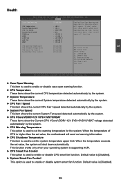
...Aptio Setup Utility - If don't enter bios setup and disabled Case Open Warning one time, Instrusion Alarm don't clear,it will shut down automatically. Default value is used to enable or disable systrm smart fan function. CPU Warning Temperature CPU Shutdown Temperature CPU Smart Fan Control System Smart Fan Control [Disabled] [Disabled] [Disabled] [Disabled] → ←: Select Screen ↑ ↓: Select Item Enter: Select +/-: Change Opt. Main F-Center Advanced Boot Power Health Security Exit Case Open Warning CPU Temperature System Temperature CPU Fan Speed System...
...Aptio Setup Utility - If don't enter bios setup and disabled Case Open Warning one time, Instrusion Alarm don't clear,it will shut down automatically. Default value is used to enable or disable systrm smart fan function. CPU Warning Temperature CPU Shutdown Temperature CPU Smart Fan Control System Smart Fan Control [Disabled] [Disabled] [Disabled] [Disabled] → ←: Select Screen ↑ ↓: Select Item Enter: Select +/-: Change Opt. Main F-Center Advanced Boot Power Health Security Exit Case Open Warning CPU Temperature System Temperature CPU Fan Speed System...

User manual
Page 47
... Main F-Center Advanced Boot Power Health SSeeccuurriittyy Exit Password Description Administrator Password User Password Administrator Password HDD BootSector Write Not Installed Not Installed [Normal] Set Administrator Password. F1: General Help F2: Previous Values F3: Optimized Defaults F4: Save & Exit ESC: Exit Version 2.14.1219. If only the Administrator's password is used to enable or disable protect HDD MBR from avoiding destroied by virus. ► HDD Security Configuration "HDD Security Configuration" appears only when you connect HDD...
... Main F-Center Advanced Boot Power Health SSeeccuurriittyy Exit Password Description Administrator Password User Password Administrator Password HDD BootSector Write Not Installed Not Installed [Normal] Set Administrator Password. F1: General Help F2: Previous Values F3: Optimized Defaults F4: Save & Exit ESC: Exit Version 2.14.1219. If only the Administrator's password is used to enable or disable protect HDD MBR from avoiding destroied by virus. ► HDD Security Configuration "HDD Security Configuration" appears only when you connect HDD...
User manual
Page 50
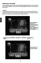
... you can click on your system. You must click "Intel Chipset Driver" to install. 1. 4 Install driver and utility This motherboard comes with one DVD, after installing the Operating System, you can simply put it into your DVD-ROM drive, and the main menu will be displayed on each individual driver to Install 43 43 Driver Use these options to install all the drivers for your PC screen to guide you how to install it first.
... you can click on your system. You must click "Intel Chipset Driver" to install. 1. 4 Install driver and utility This motherboard comes with one DVD, after installing the Operating System, you can simply put it into your DVD-ROM drive, and the main menu will be displayed on each individual driver to Install 43 43 Driver Use these options to install all the drivers for your PC screen to guide you how to install it first.


