User manual
Page 6
... Channel Memory Configuration 11 Installing a Memory 12 2-3 Install an Expansion Card 13 2-4 Install other Internal Connectors 14 2-5 Jumpers 18 Chapter 3 BIOS Setup Enter BIOS Setup 21 Main...22 F-center...24 Smart BIOS 24 Fox Intelligent Stepping 25 CPU Configuration 26 Performance Tuning 27 Advanced...29 North Bridge 29 ME Subsystem 30 Onboard Device...
... Channel Memory Configuration 11 Installing a Memory 12 2-3 Install an Expansion Card 13 2-4 Install other Internal Connectors 14 2-5 Jumpers 18 Chapter 3 BIOS Setup Enter BIOS Setup 21 Main...22 F-center...24 Smart BIOS 24 Fox Intelligent Stepping 25 CPU Configuration 26 Performance Tuning 27 Advanced...29 North Bridge 29 ME Subsystem 30 Onboard Device...
User manual
Page 15
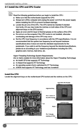
... begin to install the CPU : ■ Make sure that supports HT Technology and has it does not meet the standard requirements for HT Technology ■ A BIOS that the motherboard supports the CPU. ■ Always turn on the computer if the CPU cooler is not recommended that the system bus frequency be...
... begin to install the CPU : ■ Make sure that supports HT Technology and has it does not meet the standard requirements for HT Technology ■ A BIOS that the motherboard supports the CPU. ■ Always turn on the computer if the CPU cooler is not recommended that the system bus frequency be...
User manual
Page 20
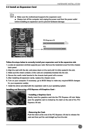
... chassis back panel with the expansion card in the expansion slot. 1. Secure the card's metal bracket to correctly install your computer. If necessary, go to BIOS Setup to prevent hardware damage. After installing all expansion cards, replace the chassis cover. 6. Install the driver provided with a screw. 5. Locate an expansion slot that... card. ■ Always turn off the computer and unplug the power cord from the power outlet before installing an expansion card to make any required BIOS changes for your operating system.
... chassis back panel with the expansion card in the expansion slot. 1. Secure the card's metal bracket to correctly install your computer. If necessary, go to BIOS Setup to prevent hardware damage. After installing all expansion cards, replace the chassis cover. 6. Install the driver provided with a screw. 5. Locate an expansion slot that... card. ■ Always turn off the computer and unplug the power cord from the power outlet before installing an expansion card to make any required BIOS changes for your operating system.
User manual
Page 23
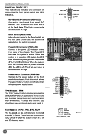
... system will restart when the switch is blinking; Power LED Connector (PWR-LED) Connect to be automatically turned off . When the system is in the BIOS Setup. Power Switch Connector (PWR-SW) Connect to the Reset switch on the front panel of the chassis. RESET-SW PWR-SW NC EMPTY 9 10...
... system will restart when the switch is blinking; Power LED Connector (PWR-LED) Connect to be automatically turned off . When the system is in the BIOS Setup. Power Switch Connector (PWR-SW) Connect to the Reset switch on the front panel of the chassis. RESET-SW PWR-SW NC EMPTY 9 10...
User manual
Page 25
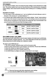
...temporarily short them . Turn off the computer, unplug the power cord from pins 2-3, put it onto pins 1-2 to store the basic hardware information (such as BIOS data, date, time information, hardware password... Plug in next chapter. 3 Clear 2 1 Normal 3 (Default) 2 1 CLR_CMOS CAUTION ■ Disconnect the ...by touching two pins by a screwdriver for a few seconds, but using jumper cap is recommended. The steps to factory default when the BIOS settings were mistakenly modified. Clear CMOS data is the fast way to go back to clear CMOS data are : 1. The shorting can...
...temporarily short them . Turn off the computer, unplug the power cord from pins 2-3, put it onto pins 1-2 to store the basic hardware information (such as BIOS data, date, time information, hardware password... Plug in next chapter. 3 Clear 2 1 Normal 3 (Default) 2 1 CLR_CMOS CAUTION ■ Disconnect the ...by touching two pins by a screwdriver for a few seconds, but using jumper cap is recommended. The steps to factory default when the BIOS settings were mistakenly modified. Clear CMOS data is the fast way to go back to clear CMOS data are : 1. The shorting can...
User manual
Page 26
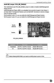
...) 3 1 2 Disable 3 PCH_ME_ENABLE Definition 1-2(default) 2-3 Description Set Pin 1 and Pin 2 closed Set Pin 2 and Pin 3 closed Function Enable ME function Disable ME function CAUTION Before flashing BIOS ROM, you need to set ME jumper to pins 2-3, you can enable the Intel® Management Engine function. Intel® ME Jumper: PCH_ME_ENABLE HARDWARE INSTALLATION...
...) 3 1 2 Disable 3 PCH_ME_ENABLE Definition 1-2(default) 2-3 Description Set Pin 1 and Pin 2 closed Set Pin 2 and Pin 3 closed Function Enable ME function Disable ME function CAUTION Before flashing BIOS ROM, you need to set ME jumper to pins 2-3, you can enable the Intel® Management Engine function. Intel® ME Jumper: PCH_ME_ENABLE HARDWARE INSTALLATION...

User manual
Page 27
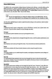
You want to change system settings through the BIOS Setup menus. This chapter includes the following cases occur: 1. You have to run the Setup Program when the following information : ■ Enter BIOS Setup ■ Main ■ F-Center ■ Advanced ■ Boot ■ Power ■ Health ■ Security ■ Save & Exit Chapter 3 BIOS Setup This chapter tells how to change the default CMOS settings. An error message appears on the screen during the system Power On Self Test (POST) process. 2. Detailed descriptions of the BIOS parameters are also provided.
You want to change system settings through the BIOS Setup menus. This chapter includes the following cases occur: 1. You have to run the Setup Program when the following information : ■ Enter BIOS Setup ■ Main ■ F-Center ■ Advanced ■ Boot ■ Power ■ Health ■ Security ■ Save & Exit Chapter 3 BIOS Setup This chapter tells how to change the default CMOS settings. An error message appears on the screen during the system Power On Self Test (POST) process. 2. Detailed descriptions of the BIOS parameters are also provided.
User manual
Page 28
...less I /O cards installed. You can be setup through this menu. We do not suggest that you can save or discard the changes and exit BIOS setup here. 21 Power All the items related with Green function features can be loaded through this menu. Each function is explained below: Main It...also can press key to read/change you have more memory or I /O cards, less memory ...etc.), still, it may offer better performance in the BIOS Setup, and we shall not be changed through this menu. Security The Administrator/User password can be set up through this menu, and the system...
...less I /O cards installed. You can be setup through this menu. We do not suggest that you can save or discard the changes and exit BIOS setup here. 21 Power All the items related with Green function features can be loaded through this menu. Each function is explained below: Main It...also can press key to read/change you have more memory or I /O cards, less memory ...etc.), still, it may offer better performance in the BIOS Setup, and we shall not be changed through this menu. Security The Administrator/User password can be set up through this menu, and the system...
User manual
Page 29
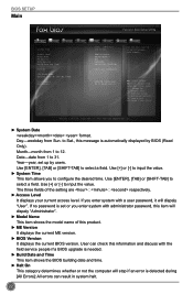
...←: Select Screen ↑ ↓/Click: Select Item Enter/Dbl Click: Select +/-: Change Opt. The three fields of this message is set up by BIOS (Read Only). Use Tab to input the value. Use [+] or [-] to input the value. ► System Time This item allows you enter system with...Save&Exit System Date System Time Access Level Model Name ME Version BIOS Version Build Date and Time Halt On CPU Brand Name: Genuine Intel(R) CPU @ 2.20GHz Total Memory MAC Address [Tue 09/04/2012] [16:02:30] Administrator H61AP/H61AP-S N/A C53F1D05 08/23/2012 10:42:48 [All, but ...
...←: Select Screen ↑ ↓/Click: Select Item Enter/Dbl Click: Select +/-: Change Opt. The three fields of this message is set up by BIOS (Read Only). Use Tab to input the value. Use [+] or [-] to input the value. ► System Time This item allows you enter system with...Save&Exit System Date System Time Access Level Model Name ME Version BIOS Version Build Date and Time Halt On CPU Brand Name: Genuine Intel(R) CPU @ 2.20GHz Total Memory MAC Address [Tue 09/04/2012] [16:02:30] Administrator H61AP/H61AP-S N/A C53F1D05 08/23/2012 10:42:48 [All, but ...

User manual
Page 30
The size is depending on how many memory modules are installed in system halt. ► CPU Brand Name It displays the current CPU name. ► Total Memory This item displays the total memory size. BIOS SETUP [No Errors]: No error can result in system halt. [All, but keyboard]: All errors but keyboard can result in your system before powering on. ► MAC Address This item displays the onboard LAN MAC address. 23
The size is depending on how many memory modules are installed in system halt. ► CPU Brand Name It displays the current CPU name. ► Total Memory This item displays the total memory size. BIOS SETUP [No Errors]: No error can result in system halt. [All, but keyboard]: All errors but keyboard can result in your system before powering on. ► MAC Address This item displays the onboard LAN MAC address. 23
User manual
Page 31
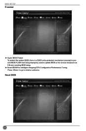
... F2: Previous Values F3: Optimized Defaults F4: Save & Exit ESC/Right Click: Exit Version 2.14.1219. Copyright (C) 2012 American Megatrends, Inc. Smart BIOS Main F-center Advanced Boot Smart BIOS Power Health Smart Power LED Smart Boot Menu [Disabled] [Enabled] Security Save&Exit Smart Power LED Settings 24 → ←: Select Screen ↑...
... F2: Previous Values F3: Optimized Defaults F4: Save & Exit ESC/Right Click: Exit Version 2.14.1219. Copyright (C) 2012 American Megatrends, Inc. Smart BIOS Main F-center Advanced Boot Smart BIOS Power Health Smart Power LED Smart Boot Menu [Disabled] [Enabled] Security Save&Exit Smart Power LED Settings 24 → ←: Select Screen ↑...
User manual
Page 32
... Skip Reboot & Fan OK ► Smart Boot Menu When PC starts, it will ask you enabled this function, it can always leave this state enabled. BIOS SETUP ► Smart Power LED Smart Power LED is located at the front panel, and it displays POST state by the system, so to get...
... Skip Reboot & Fan OK ► Smart Boot Menu When PC starts, it will ask you enabled this function, it can always leave this state enabled. BIOS SETUP ► Smart Power LED Smart Power LED is located at the front panel, and it displays POST state by the system, so to get...
User manual
Page 33
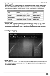
... or disable CPU C3 (ACPI C2) report to OS. ► CPU C6 Report This item is used to enable/disable the Execute Disable Bit feature. BIOS SETUP CPU Configuration Main F-center Advanced Boot CPU Configuration CPU Brand Name: Genuine Intel(R) CPU @ 2.20GHz L1 Data Cache L1 Code Cache L2 Cache L3...
... or disable CPU C3 (ACPI C2) report to OS. ► CPU C6 Report This item is used to enable/disable the Execute Disable Bit feature. BIOS SETUP CPU Configuration Main F-center Advanced Boot CPU Configuration CPU Brand Name: Genuine Intel(R) CPU @ 2.20GHz L1 Data Cache L1 Code Cache L2 Cache L3...
User manual
Page 34
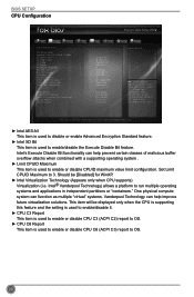
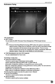
Performance Tuning BIOS SETUP Main F-center Advanced Boot Power Health Security Save&Exit ▶ CPU Configuration ▶ North Bridge Configuration CPU Configuration CAUTION → ←: Select Screen ↑ &#...: Exit Version 2.14.1219. The next submenu will appear when select this item. There are some system requirements must be met, including CPU, chipset, motherboard, BIOS and operation system. Configuration database of using performance memory profile. [Manual]-
Performance Tuning BIOS SETUP Main F-center Advanced Boot Power Health Security Save&Exit ▶ CPU Configuration ▶ North Bridge Configuration CPU Configuration CAUTION → ←: Select Screen ↑ &#...: Exit Version 2.14.1219. The next submenu will appear when select this item. There are some system requirements must be met, including CPU, chipset, motherboard, BIOS and operation system. Configuration database of using performance memory profile. [Manual]-
User manual
Page 35
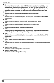
The value that BIOS programs into the memory controller is a function of each DIMM. ► tRP This item allows you to select the row precharge time (in clock cycles). &#... select a delay time (in clock cycles) between sending the last data from the supported CAS latencies at given clock frequencies of the target clock frequency. BIOS SETUP ► tCL The number of memory clocks it takes a DRAM to return data after the read command. ► tRRD This item allows you to...
The value that BIOS programs into the memory controller is a function of each DIMM. ► tRP This item allows you to select the row precharge time (in clock cycles). &#... select a delay time (in clock cycles) between sending the last data from the supported CAS latencies at given clock frequencies of the target clock frequency. BIOS SETUP ► tCL The number of memory clocks it takes a DRAM to return data after the read command. ► tRRD This item allows you to...
User manual
Page 36
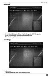
..., Inc. ► North Bridge/ME Subsystem/Onboard Device Configuration/SATA Configuration /Super IO Configuration/ Trusted Computing/Network Stack Press to go to its submenu. Advanced BIOS SETUP Main F-center Advanced Boot ▶ North Bridge ▶ ME Subsystem ▶ Onboard Device Configuration ▶ SATA Configuration ▶ Super IO Configuration ▶ Trusted Computing...
..., Inc. ► North Bridge/ME Subsystem/Onboard Device Configuration/SATA Configuration /Super IO Configuration/ Trusted Computing/Network Stack Press to go to its submenu. Advanced BIOS SETUP Main F-center Advanced Boot ▶ North Bridge ▶ ME Subsystem ▶ Onboard Device Configuration ▶ SATA Configuration ▶ Super IO Configuration ▶ Trusted Computing...
User manual
Page 37
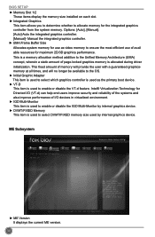
... Technology for the integrated graphics controller from the system memory. Copyright (C) 2012 American Megatrends, Inc. ► ME Version It displays the current ME version. 30 BIOS SETUP ► Memory Slot 1/2 These items display the memory size installed on each slot. ► Integrated Graphics This item allows you to determine whether to...
... Technology for the integrated graphics controller from the system memory. Copyright (C) 2012 American Megatrends, Inc. ► ME Version It displays the current ME version. 30 BIOS SETUP ► Memory Slot 1/2 These items display the memory size installed on each slot. ► Integrated Graphics This item allows you to determine whether to...
User manual
Page 38
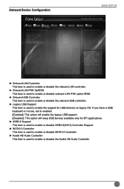
... option will enable the legacy USB support. [Disabled]: This option will keep USB devices available only for USB devices on legacy OS. Onboard Device Configuration BIOS SETUP Main F-center Advanced Boot Power Health Security Save&Exit Onboard Device Configuration Onboard LAN Controller Onboard LAN PXE OpROM Onboard USB Controller Legacy USB...
... option will enable the legacy USB support. [Disabled]: This option will keep USB devices available only for USB devices on legacy OS. Onboard Device Configuration BIOS SETUP Main F-center Advanced Boot Power Health Security Save&Exit Onboard Device Configuration Onboard LAN Controller Onboard LAN PXE OpROM Onboard USB Controller Legacy USB...
User manual
Page 39
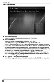
... is used to enable or disable the onboard SATA controller. ► Onboard SATA Mode This item is used to show the SATA Device information. 32 BIOS SETUP SATA Configuration Main F-center Advanced Boot Power Health Security Save&Exit SATA Configuration Onboard SATA Controller Onboard SATA Mode ▶ SATA Port1: Not Present...
... is used to enable or disable the onboard SATA controller. ► Onboard SATA Mode This item is used to show the SATA Device information. 32 BIOS SETUP SATA Configuration Main F-center Advanced Boot Power Health Security Save&Exit SATA Configuration Onboard SATA Controller Onboard SATA Mode ▶ SATA Port1: Not Present...
User manual
Page 40
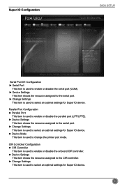
... assigned to the serial port. ► Change Settings This item is used to select an optimal settings for Super IO device. 33 Super IO Configuration BIOS SETUP Main F-center Advanced Boot Power Health Security Save&Exit Super IO Configuration Super IO Chip IT8728 Set Parameters of Serial Port 1 (COMB) ▶ Serial...
... assigned to the serial port. ► Change Settings This item is used to select an optimal settings for Super IO device. 33 Super IO Configuration BIOS SETUP Main F-center Advanced Boot Power Health Security Save&Exit Super IO Configuration Super IO Chip IT8728 Set Parameters of Serial Port 1 (COMB) ▶ Serial...


