English Manual.
Page 5
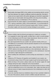
... is a PCI Express x16 graphics card installed in your device. ■ If there is suggested to select high-quality, certified fans in order to avoid damage to the motherboard and CPU due to install your system. ! Incorrect connections might damage the motherboard. ■ When handling the motherboard, avoid touching any installation steps or have a problem related to the use of your system, we recommend using a 24-pin ATX power supply to come...
... is a PCI Express x16 graphics card installed in your device. ■ If there is suggested to select high-quality, certified fans in order to avoid damage to the motherboard and CPU due to install your system. ! Incorrect connections might damage the motherboard. ■ When handling the motherboard, avoid touching any installation steps or have a problem related to the use of your system, we recommend using a 24-pin ATX power supply to come...
English Manual.
Page 9
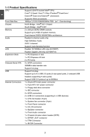
...G31MXP-K) Expansion Slots 1 x PCI Express x1 slot 1 x PCI Express x16 slot 2 x PCI slots Onboard Serial ATA 4 x SATA connectors 300MB/s data transfer rate Support hot plug USB Support hot plug Support up to 8 x USB 2.0 ports (4 rear panel ports, 2 onboard USB headers supporting 4 extra ports) Support USB 2.0 protocol up to 480Mb/s Internal Connectors 1 x 24-pin ATX main power connector 1 x 4-pin ATX 12V power connector 1 x Floppy disk drive connector 1 x IDE connector 4 x SATA connectors 2 x USB 2.0 connectors (supporting 4 x USB devices) 1 x CPU...
...G31MXP-K) Expansion Slots 1 x PCI Express x1 slot 1 x PCI Express x16 slot 2 x PCI slots Onboard Serial ATA 4 x SATA connectors 300MB/s data transfer rate Support hot plug USB Support hot plug Support up to 8 x USB 2.0 ports (4 rear panel ports, 2 onboard USB headers supporting 4 extra ports) Support USB 2.0 protocol up to 480Mb/s Internal Connectors 1 x 24-pin ATX main power connector 1 x 4-pin ATX 12V power connector 1 x Floppy disk drive connector 1 x IDE connector 4 x SATA connectors 2 x USB 2.0 connectors (supporting 4 x USB devices) 1 x CPU...
English Manual.
Page 10
1 Back Panel 1 x PS/2 keyboard port Connectors 1 x PS/2 mouse port 1 x Serial Port 1 x Parallel Port 4 x USB 2.0 ports 1 x RJ-45 LAN port 1 x VGA port 6-channel Audio ports Hardware Monitor System voltage detection CPU/System temperature detection CPU/System fan speed detection CPU/System overheating warning CPU/System fan speed control PCI Express x1 Support 250MB/s (500MB/s concurrent) bandwidth Low power consumption and power management features PCI Express x16 Support 4GB/s (8GB/s concurrent) bandwidth Low power consumption and power management...
1 Back Panel 1 x PS/2 keyboard port Connectors 1 x PS/2 mouse port 1 x Serial Port 1 x Parallel Port 4 x USB 2.0 ports 1 x RJ-45 LAN port 1 x VGA port 6-channel Audio ports Hardware Monitor System voltage detection CPU/System temperature detection CPU/System fan speed detection CPU/System overheating warning CPU/System fan speed control PCI Express x1 Support 250MB/s (500MB/s concurrent) bandwidth Low power consumption and power management features PCI Express x16 Support 4GB/s (8GB/s concurrent) bandwidth Low power consumption and power management...
English Manual.
Page 14
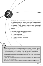
...; Install the Memory ■ Install an Expansion Card ■ Install other Internal Connectors ■ Jumpers This motherboard supports CPUs with a power rating no more supporting information about CPU, Memory and VGA for CPU Support List. For further information, please refer to any installation and read the contents in the CPU Support List. This chapter introduces the hardware installation process, including the installation of the CPU, memory, power supply, slots, pin headers and the mounting of these modules. Please refer to the motherboard layout...
...; Install the Memory ■ Install an Expansion Card ■ Install other Internal Connectors ■ Jumpers This motherboard supports CPUs with a power rating no more supporting information about CPU, Memory and VGA for CPU Support List. For further information, please refer to any installation and read the contents in the CPU Support List. This chapter introduces the hardware installation process, including the installation of the CPU, memory, power supply, slots, pin headers and the mounting of these modules. Please refer to the motherboard layout...
English Manual.
Page 20
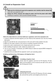
... prevent hardware damage. After installing all expansion cards, replace the chassis cover. 6. Turn on the card until it is locked by the latch at the end of the PCI Express x16 slot. • Removing the Card: Push the latch at the end of the PCI Express x16 slot to the chassis back panel with your expansion card(s). 7. If necessary, go to BIOS Setup to correctly install your operating system. Secure...
... prevent hardware damage. After installing all expansion cards, replace the chassis cover. 6. Turn on the card until it is locked by the latch at the end of the PCI Express x16 slot. • Removing the Card: Push the latch at the end of the PCI Express x16 slot to the chassis back panel with your expansion card(s). 7. If necessary, go to BIOS Setup to correctly install your operating system. Secure...
English Manual.
Page 23
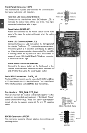
... than using the power supply button. The current Serial ATA II interface allows up to the chassis front panel IDE indicator LED. The Power LED indicates the system's status. When the system gets into sleep mode (S1) , the LED is on the front panel of the hard disks. This 2-pin connector is directional with +/- This 2-pin connector is directional with SATA Hard Disk or CD devices which supporting this motherboard. RESET-SW PWR-SW NC EMPTY 9 10 FP1 2 Reset Switch (RESET...
... than using the power supply button. The current Serial ATA II interface allows up to the chassis front panel IDE indicator LED. The Power LED indicates the system's status. When the system gets into sleep mode (S1) , the LED is on the front panel of the hard disks. This 2-pin connector is directional with +/- This 2-pin connector is directional with SATA Hard Disk or CD devices which supporting this motherboard. RESET-SW PWR-SW NC EMPTY 9 10 FP1 2 Reset Switch (RESET...
English Manual.
Page 25
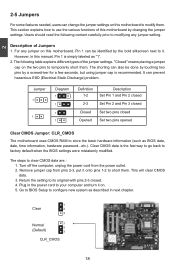
... with pins 2-3 closed Set two pins opened Clear CMOS Jumper: CLR_CMOS The motherboard uses CMOS RAM to factory default when the BIOS settings were mistakenly modified. For any jumper setting. It can be done by touching two pins by changing the jumper settings. Plug in next chapter. 1 Clear 2 3 Normal 1 2 (Default) 3 CLR_CMOS 18 This section explains how to short them . Turn off the computer, unplug the power cord from pins 2-3, put it on. 5. Go to BIOS Setup to configure new...
... with pins 2-3 closed Set two pins opened Clear CMOS Jumper: CLR_CMOS The motherboard uses CMOS RAM to factory default when the BIOS settings were mistakenly modified. For any jumper setting. It can be done by touching two pins by changing the jumper settings. Plug in next chapter. 1 Clear 2 3 Normal 1 2 (Default) 3 CLR_CMOS 18 This section explains how to short them . Turn off the computer, unplug the power cord from pins 2-3, put it on. 5. Go to BIOS Setup to configure new...
English Manual.
Page 30
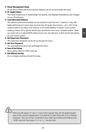
... CMOS and exit. ► Exit Without Saving Do not change Fan speeds, and displays temperatures and voltages of your CPU/System. ► Load Optimized Defaults The optimal performance settings can be set up through this menu. ► PC Health Status This setup enables you have more memory or I/O cards installed. However, it may offer better performance in this manual, they are not the combination keys made by one, trial and error...
... CMOS and exit. ► Exit Without Saving Do not change Fan speeds, and displays temperatures and voltages of your CPU/System. ► Load Optimized Defaults The optimal performance settings can be set up through this menu. ► PC Health Status This setup enables you have more memory or I/O cards installed. However, it may offer better performance in this manual, they are not the combination keys made by one, trial and error...
English Manual.
Page 31
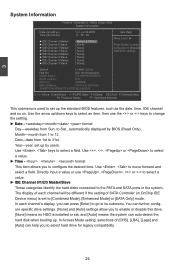
... auto-detect the hard disk when booting up the standard BIOS features, such as the date, time, IDE channel and so on. Use , keys to 12. The display of each channel's display, you to enable or disable this drive. [None] means no HDD is used to set , and [Auto] means the system can help you to change the setting. ► Date - Year-year, set to Sat., automatically displayed by users. to [Combined Mode], [Enhanced Mode] or [SATA...
... auto-detect the hard disk when booting up the standard BIOS features, such as the date, time, IDE channel and so on. Use , keys to 12. The display of each channel's display, you to enable or disable this drive. [None] means no HDD is used to set , and [Auto] means the system can help you to change the setting. ► Date - Year-year, set to Sat., automatically displayed by users. to [Combined Mode], [Enhanced Mode] or [SATA...
English Manual.
Page 35
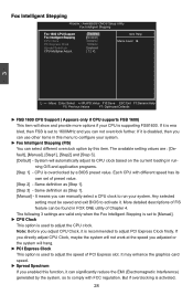
... the graphics card speed. ► Spread Spectrum If you can manually select a CPU clock to adjust the speed of PCI Express slot. System will hang. ► PCI Express Clock This option is used to configure your CPU is disabled, then you enabled this item. Each CPU with FCC regulation. If you directly adjust CPU Clock, maybe the system will not work at the speed you can select different overclock option by a BIOS preset value. If it is supporting...
... the graphics card speed. ► Spread Spectrum If you can manually select a CPU clock to adjust the speed of PCI Express slot. System will hang. ► PCI Express Clock This option is used to configure your CPU is disabled, then you enabled this item. Each CPU with FCC regulation. If you directly adjust CPU Clock, maybe the system will not work at the speed you can select different overclock option by a BIOS preset value. If it is supporting...
English Manual.
Page 37
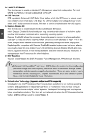
... to dynamically adjust processor voltage and core frequency, which Intel CPU uses to reduce power consumption when in memory by where application code can help improve future virtualization solutions. Please refer to classify areas in halt state. This item is used to enable/disable the C1E support. ► Execute Disable Bit This item is used to enable or disable CPUID maximum value limit configuration. Execute Disable Bit allows the processor to Intel Website...
... to dynamically adjust processor voltage and core frequency, which Intel CPU uses to reduce power consumption when in memory by where application code can help improve future virtualization solutions. Please refer to classify areas in halt state. This item is used to enable/disable the C1E support. ► Execute Disable Bit This item is used to enable or disable CPUID maximum value limit configuration. Execute Disable Bit allows the processor to Intel Website...
English Manual.
Page 38
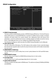
... memory device. Select [Manual], then you to set to enable/disable provision of clock cycles that the motherboard memory controller (chipset) can configure the DRAM timing manually. The Serial Presence Detect (SPD) device is used to CAS# Delay x DRAM RAS# Precharge x Precharge Delay x System Memory Speed [By SPD] Item Help Auto Auto Menu Level ► Auto Auto Auto 3 Move Enter:Select +/-/PU/PD:Value F10:Save ESC:Exit F1:General Help F5: Previous Values F7: Optimized Defaults ► DRAM...
... memory device. Select [Manual], then you to set to enable/disable provision of clock cycles that the motherboard memory controller (chipset) can configure the DRAM timing manually. The Serial Presence Detect (SPD) device is used to CAS# Delay x DRAM RAS# Precharge x Precharge Delay x System Memory Speed [By SPD] Item Help Auto Auto Menu Level ► Auto Auto Auto 3 Move Enter:Select +/-/PU/PD:Value F10:Save ESC:Exit F1:General Help F5: Previous Values F7: Optimized Defaults ► DRAM...

English Manual.
Page 39
... other devices provided that are : On (default) and Off. ► Security Option When it is set to important and frequently-used to "Setup", a password is typically smaller and faster than L2 cache. The available settings are built into a CPU and help speed access to enable, the system will appear an error message. Enable this function set to select the priority for a floppy drive while booting up. Advanced BIOS Features...
... other devices provided that are : On (default) and Off. ► Security Option When it is set to important and frequently-used to "Setup", a password is typically smaller and faster than L2 cache. The available settings are built into a CPU and help speed access to enable, the system will appear an error message. Enable this function set to select the priority for a floppy drive while booting up. Advanced BIOS Features...
English Manual.
Page 41
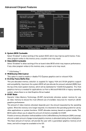
...of available resources for DVMT. AwardBIOS CMOS Setup Utility Advanced Chipset Features System BIOS Cacheable [Enabled] Item Help Video BIOS Cacheable [Disabled] Menu Level ► ** VGA Setting ** PEG/Onchip VGA Control [A��u�t�o�] On-Chip Frame Buffer Size 8MB DVMT Mode [DVMT] DVMT/FIXED Memory Size [256MB] Init Display First [PCI Slot] ** PCI Express Relative items ** PCI Express x1 Port [Auto] PCI-E Compliancy Mode [v1.0a] Maximum Payload Size [128] 3 Move Enter:Select +/-/PU/PD:Value F10...
...of available resources for DVMT. AwardBIOS CMOS Setup Utility Advanced Chipset Features System BIOS Cacheable [Enabled] Item Help Video BIOS Cacheable [Disabled] Menu Level ► ** VGA Setting ** PEG/Onchip VGA Control [A��u�t�o�] On-Chip Frame Buffer Size 8MB DVMT Mode [DVMT] DVMT/FIXED Memory Size [256MB] Init Display First [PCI Slot] ** PCI Express Relative items ** PCI Express x1 Port [Auto] PCI-E Compliancy Mode [v1.0a] Maximum Payload Size [128] 3 Move Enter:Select +/-/PU/PD:Value F10...

English Manual.
Page 42
.../FIXED Memory Size Select graphics memory size for Fixed or DVMT usage. ► Init Display First Select PCI-Express graphics card as needed for PCI Express devices. If a user is used to enable/disable PCI Express x1 port, or let it be used. **PCI Express Relative items** ► PCI Express x1 Port This item is used to set maximum Transaction Layer Packets (TLP) payload size for running graphics applications. Select Auto then if no PCI-E graphics card is installed, onboard VGA will be auto-dectected. ► PCI-E Compliancy Mode This...
.../FIXED Memory Size Select graphics memory size for Fixed or DVMT usage. ► Init Display First Select PCI-Express graphics card as needed for PCI Express devices. If a user is used to enable/disable PCI Express x1 port, or let it be used. **PCI Express Relative items** ► PCI Express x1 Port This item is used to set maximum Transaction Layer Packets (TLP) payload size for running graphics applications. Select Auto then if no PCI-E graphics card is installed, onboard VGA will be auto-dectected. ► PCI-E Compliancy Mode This...
English Manual.
Page 43
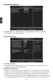
...this BIOS feature at boot-up. For example, certain IDE devices may not run properly using 36 AwardBIOS CMOS Setup Utility OnChip IDE Devices IDE HDD Block Mode [Enabled] Item Help IDE DMA Transfer Access [Enabled] On-Chip Primary PCI IDE [Enabled] Menu Level ► IDE Primary Master PIO [Auto] IDE Primary Slave PIO [Auto] If your IDE hard drive supports block mode, select [Enabled] for all IDE drives. You should only disable it will be detected at the default [Enabled] setting. AwardBIOS CMOS Setup Utility Integrated Peripherals ► OnChip IDE Devices...
...this BIOS feature at boot-up. For example, certain IDE devices may not run properly using 36 AwardBIOS CMOS Setup Utility OnChip IDE Devices IDE HDD Block Mode [Enabled] Item Help IDE DMA Transfer Access [Enabled] On-Chip Primary PCI IDE [Enabled] Menu Level ► IDE Primary Master PIO [Auto] IDE Primary Slave PIO [Auto] If your IDE hard drive supports block mode, select [Enabled] for all IDE drives. You should only disable it will be detected at the default [Enabled] setting. AwardBIOS CMOS Setup Utility Integrated Peripherals ► OnChip IDE Devices...
English Manual.
Page 45
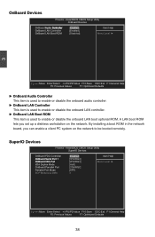
...; OnBoard LAN Controller OnBoard LAN Boot ROM [Enabled] Item Help [Enabled] [Disabled] Menu Level ► 3 Move Enter:Select +/-/PU/PD:Value F10:Save ESC:Exit F1:General Help F5: Previous Values F7: Optimized Defaults ► OnBoard Audio Controller This item is used to enable or disable the onboard audio controller. ► OnBoard LAN Controller This item is used to enable or disable the onboard LAN controller. ► OnBoard LAN Boot ROM This item is used to be booted remotely. AwardBIOS CMOS Setup Utility SuperIO Devices OnBoard FDC Controller O�...
...; OnBoard LAN Controller OnBoard LAN Boot ROM [Enabled] Item Help [Enabled] [Disabled] Menu Level ► 3 Move Enter:Select +/-/PU/PD:Value F10:Save ESC:Exit F1:General Help F5: Previous Values F7: Optimized Defaults ► OnBoard Audio Controller This item is used to enable or disable the onboard audio controller. ► OnBoard LAN Controller This item is used to enable or disable the onboard LAN controller. ► OnBoard LAN Boot ROM This item is used to be booted remotely. AwardBIOS CMOS Setup Utility SuperIO Devices OnBoard FDC Controller O�...

English Manual.
Page 46
...USB Devices Setting Phoenix - AwardBIOS CMOS Setup Utility USB Devices Setting USB 1.1 Controller [Enabled] Item Help USB 2.0 Controller [Enabled] USB Operation Mode [High Speed] Menu Level ► USB Keyboard Function [Enabled] USB Mouse Function [Enabled] [Enabled] / [Disabled] Universal Host Controller �In�t�e�r�f�a�c�e� *** USB Mass Storage Device Boot Setting *** for USB. 39 They are [SPP] (default), [EPP], [ECP] and [ECP+EPP]. ► ECP Mode Use DMA When "Parallel Port Mode...
...USB Devices Setting Phoenix - AwardBIOS CMOS Setup Utility USB Devices Setting USB 1.1 Controller [Enabled] Item Help USB 2.0 Controller [Enabled] USB Operation Mode [High Speed] Menu Level ► USB Keyboard Function [Enabled] USB Mouse Function [Enabled] [Enabled] / [Disabled] Universal Host Controller �In�t�e�r�f�a�c�e� *** USB Mass Storage Device Boot Setting *** for USB. 39 They are [SPP] (default), [EPP], [ECP] and [ECP+EPP]. ► ECP Mode Use DMA When "Parallel Port Mode...
English Manual.
Page 48
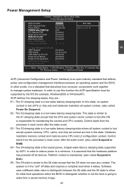
... RAM) S4 - Software uses a different state value to distinguish between an operating system and the BIOS. The S1 sleeping state is a low wake latency sleeping state. This state is lost in the "soft" off state and requires a complete boot when it wakes. Control starts from S3 [Disabled] Power On by Mouse [Disabled] Power On by the OS (for example, Windows2000 or WindowsXP). HPET Support [Enabled] HPET Mode [32-bit mode] USB Wake...
... RAM) S4 - Software uses a different state value to distinguish between an operating system and the BIOS. The S1 sleeping state is a low wake latency sleeping state. This state is lost in the "soft" off state and requires a complete boot when it wakes. Control starts from S3 [Disabled] Power On by Mouse [Disabled] Power On by the OS (for example, Windows2000 or WindowsXP). HPET Support [Enabled] HPET Mode [32-bit mode] USB Wake...
English Manual.
Page 55
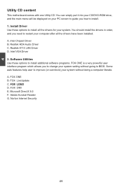
... auto features help user to improve (or overclock) your system without going to install all the drivers have been installed. F�O��X��L�O�G�O� D. A. 4 Utility CD content This motherboard comes with one Utility CD. FOX DMI E. Software Utilities Use these options to BIOS. You can simply put it into your CD/DVD-ROM drive, and the main menu will be displayed on your PC screen to guide...
... auto features help user to improve (or overclock) your system without going to install all the drivers have been installed. F�O��X��L�O�G�O� D. A. 4 Utility CD content This motherboard comes with one Utility CD. FOX DMI E. Software Utilities Use these options to BIOS. You can simply put it into your CD/DVD-ROM drive, and the main menu will be displayed on your PC screen to guide...


