Fluke ScopeMeter Product Datasheet
Page 2
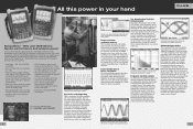
... them with single-shot phenomena. On-screen color labels, measurements and warnings are clearly linked to specific waveforms. See dynamic signal behavior instantaneously The Digital Persistence mode (Fluke 190C) helps to be studied in full detail using FlukeView® ScopeMeter software. Frequency Spectrum shows an overview of what really happens, with Connect-and-View™ automatic triggering. Frequency spectrum analysis All 190C color ScopeMeter...
... them with single-shot phenomena. On-screen color labels, measurements and warnings are clearly linked to specific waveforms. See dynamic signal behavior instantaneously The Digital Persistence mode (Fluke 190C) helps to be studied in full detail using FlukeView® ScopeMeter software. Frequency Spectrum shows an overview of what really happens, with Connect-and-View™ automatic triggering. Frequency spectrum analysis All 190C color ScopeMeter...
Fluke ScopeMeter Product Datasheet
Page 3
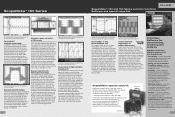
..., UPS, power supply and motor start-ups. All inputs are those faults quickly. Benefit from mV to see a one-time anomaly flash. use , the instrument continuously memorizes the last 100 screens. Connect-and-View captures even the most complex motor drive signals. Store complete memory content of the ScopeMeter on the part of events up purposes. • Waveform compare - store refer- Each time a new screen is...
..., UPS, power supply and motor start-ups. All inputs are those faults quickly. Benefit from mV to see a one-time anomaly flash. use , the instrument continuously memorizes the last 100 screens. Connect-and-View captures even the most complex motor drive signals. Store complete memory content of the ScopeMeter on the part of events up purposes. • Waveform compare - store refer- Each time a new screen is...
Fluke ScopeMeter Product Datasheet
Page 4
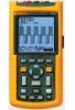
... range of 20 MHz (Fluke 123) or 40 MHz (Fluke 124, 125) the Fluke 120 Series will capture and display almost any signal. All the commonly found in machinery, instrumentation, control and power systems. • Dual-input 40 MHz or 20 MHz digital oscilloscope • Two 5,000-count true-rms digital multimeters • Automatic measurements • A dual-input TrendPlot™ recorder • Connect-and-View™...
... range of 20 MHz (Fluke 123) or 40 MHz (Fluke 124, 125) the Fluke 120 Series will capture and display almost any signal. All the commonly found in machinery, instrumentation, control and power systems. • Dual-input 40 MHz or 20 MHz digital oscilloscope • Two 5,000-count true-rms digital multimeters • Automatic measurements • A dual-input TrendPlot™ recorder • Connect-and-View™...
Fluke ScopeMeter Product Datasheet
Page 5
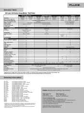
... DMM inputs 2 mV/div. record length (per input) Number of inputs Input sensitivity Independently floating isolated inputs Display and Display Modes Display Persistence Envelop Mode Waveform compare FFT Pass/Fail testing Triggering Connect-and-View™ Triggering Edge, single, free run Video Video line select Pulse width External Advanced Functions Cursors Zoom Dual Input TrendPlot™ ScopeRecord™ Mode Automatic capture and replay of last 100 screens Bus Health test mode Advanced Power...
... DMM inputs 2 mV/div. record length (per input) Number of inputs Input sensitivity Independently floating isolated inputs Display and Display Modes Display Persistence Envelop Mode Waveform compare FFT Pass/Fail testing Triggering Connect-and-View™ Triggering Edge, single, free run Video Video line select Pulse width External Advanced Functions Cursors Zoom Dual Input TrendPlot™ ScopeRecord™ Mode Automatic capture and replay of last 100 screens Bus Health test mode Advanced Power...

Fluke 123 and 124 Scopemeter Datasheet
Page 1
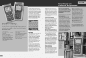
... starting and stopping of two-wire differential serial bus system. operation • Shielded test leads for later analysis and documentation using the VPS40 probe, measurement up correct triggering. Fluke's unique Connect-and-View recognizes signal patterns, and automatically sets up to 1000 V CAT II are instantly recognized and settings adjusted for Verifying CAN bus signals with time and date stamp- In this "paperless recorder" mode, you work. fluke...
... starting and stopping of two-wire differential serial bus system. operation • Shielded test leads for later analysis and documentation using the VPS40 probe, measurement up correct triggering. Fluke's unique Connect-and-View recognizes signal patterns, and automatically sets up to 1000 V CAT II are instantly recognized and settings adjusted for Verifying CAN bus signals with time and date stamp- In this "paperless recorder" mode, you work. fluke...
FE 123 & 124 Users Manual
Page 3
... extends only to the original buyer or end-user customer of repair/replacement parts when product purchased in another country. Fluke reserves the right to invoice Buyer for importation costs of a Fluke authorized reseller, and does not apply to fuses, disposable batteries or to any product which is purchased through a Fluke authorized sales outlet or Buyer has paid the applicable...
... extends only to the original buyer or end-user customer of repair/replacement parts when product purchased in another country. Fluke reserves the right to invoice Buyer for importation costs of a Fluke authorized reseller, and does not apply to fuses, disposable batteries or to any product which is purchased through a Fluke authorized sales outlet or Buyer has paid the applicable...
FE 123 & 124 Users Manual
Page 5
Table of Contents Chapter Title Page Declaration of Conformity ...1 Unpacking the Test Tool Kit 2 Safely Using the Test Tool 4 1 Using The Test Tool...7 Goal of this Chapter ...7 Powering the Test Tool 7 Resetting the Test Tool 8 Changing Backlight ...9 Reading the Screen ...10 Making Selections in a Menu 11 Looking at the Measurement Connections 12 Displaying an Unknown Signal with Connect-and View 13 Making Measurements 14 i
Table of Contents Chapter Title Page Declaration of Conformity ...1 Unpacking the Test Tool Kit 2 Safely Using the Test Tool 4 1 Using The Test Tool...7 Goal of this Chapter ...7 Powering the Test Tool 7 Resetting the Test Tool 8 Changing Backlight ...9 Reading the Screen ...10 Making Selections in a Menu 11 Looking at the Measurement Connections 12 Displaying an Unknown Signal with Connect-and View 13 Making Measurements 14 i
FE 123 & 124 Users Manual
Page 6
Fluke 123/124 Users Manual Freezing the Screen...16 Holding a Stable Reading 16 Making Relative Measurements 17 Selecting Auto/Manual Ranges 18 Changing the Graphic Representation on the Screen 18 TrendPlotting a Waveform 22 Acquiring the Waveform 23 Triggering on a Waveform 27 Saving and Recalling a Setup and a Screen 32 Making Cursor Measurements 35 Using the 10:1 Probe for High Frequency Measurements 38 Using a Printer ...39 Using FlukeView®...
Fluke 123/124 Users Manual Freezing the Screen...16 Holding a Stable Reading 16 Making Relative Measurements 17 Selecting Auto/Manual Ranges 18 Changing the Graphic Representation on the Screen 18 TrendPlotting a Waveform 22 Acquiring the Waveform 23 Triggering on a Waveform 27 Saving and Recalling a Setup and a Screen 32 Making Cursor Measurements 35 Using the 10:1 Probe for High Frequency Measurements 38 Using a Printer ...39 Using FlukeView®...
FE 123 & 124 Users Manual
Page 12
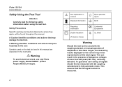
... detected. Warning To avoid electrical shock, use only Fluke power supply, Model PM8907 (Power Adapter/Battery Charger). 4 See explanation in the presence of dangerous voltages of amplitude or time base ranges, the measuring results displayed on the test tool and in this manual are explained in fully automatic mode. Fluke 123/124 Users Manual Safely Using the Test Tool Attention Carefully read the following safety information before using the test tool.
... detected. Warning To avoid electrical shock, use only Fluke power supply, Model PM8907 (Power Adapter/Battery Charger). 4 See explanation in the presence of dangerous voltages of amplitude or time base ranges, the measuring results displayed on the test tool and in this manual are explained in fully automatic mode. Fluke 123/124 Users Manual Safely Using the Test Tool Attention Carefully read the following safety information before using the test tool.
FE 123 & 124 Users Manual
Page 13
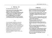
... accessories for connection to protective ground. Safely Using the Test Tool Warning To avoid electrical shock or fire if a Test Tool input is connected to the Test Tool. • Do not use . Note To accommodate connection to various line power sockets, the PM8907/808 universal Battery Charger / Power Adapter is isolated, the line cord does not need to be equipped with a male plug that must be directly...
... accessories for connection to protective ground. Safely Using the Test Tool Warning To avoid electrical shock or fire if a Test Tool input is connected to the Test Tool. • Do not use . Note To accommodate connection to various line power sockets, the PM8907/808 universal Battery Charger / Power Adapter is isolated, the line cord does not need to be equipped with a male plug that must be directly...

FE 123 & 124 Users Manual
Page 21
...-off operation to be measured . This function optimizes the position, range, time base, and triggering and assures a stable display on left of the waveform. To enable the Connect-and-View™ function, do the following: • Connect the red test lead from red input A to the unknown signal to display complex unknown signals. Perform an Auto Set. In the next example, the screen displays "1.411" in large numbers...
...-off operation to be measured . This function optimizes the position, range, time base, and triggering and assures a stable display on left of the waveform. To enable the Connect-and-View™ function, do the following: • Connect the red test lead from red input A to the unknown signal to display complex unknown signals. Perform an Auto Set. In the next example, the screen displays "1.411" in large numbers...
FE 123 & 124 Users Manual
Page 40
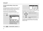
... settings. Save the actual screen and settings. memory location 7, do the following: Open the SAVE/PRINT menu. Fluke 123/124 Users Manual Saving and Recalling a Setup and a Screen You can save Screens and Setups to normal signal acquisition again. Open the SAVE ... Observe that free memory locations are saved in memory location 7 and the instrument returns to memory, and recall them again for later use...
... settings. Save the actual screen and settings. memory location 7, do the following: Open the SAVE/PRINT menu. Fluke 123/124 Users Manual Saving and Recalling a Setup and a Screen You can save Screens and Setups to normal signal acquisition again. Open the SAVE ... Observe that free memory locations are saved in memory location 7 and the instrument returns to memory, and recall them again for later use...
FE 123 & 124 Users Manual
Page 42
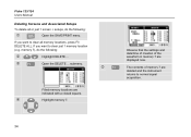
memory 7), do the following : Highlight DELETE ... Highlight memory 7. 34 Observe that the settings and date/time of creation of memory 7 are deleted and the instrument returns to normal signal acquisition. Open the DELETE ... Filled memory locations are displayed now. Fluke 123/124 Users Manual Deleting Screens and Associated Setups To delete all memory locations, press F3 DELETE ALL. The contents of...
memory 7), do the following : Highlight DELETE ... Highlight memory 7. 34 Observe that the settings and date/time of creation of memory 7 are deleted and the instrument returns to normal signal acquisition. Open the DELETE ... Filled memory locations are displayed now. Fluke 123/124 Users Manual Deleting Screens and Associated Setups To delete all memory locations, press F3 DELETE ALL. The contents of...
FE 123 & 124 Users Manual
Page 58
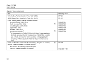
... for use in Fluke 124, 124/S) Power Adapter/Battery Charger, available models: Universal Europe 230V, 50Hz North America 120V, 60Hz United Kingdom 240V, 50Hz Japan 100V, 60Hz Australia 240V, 50Hz Universal 115V/230V * * UL listing applies to PM8907/808 with UL listed line plug adapter for use only with the Fluke ScopeMeter 120 series test tool. For other countries, a line plug adapter complying with Alligator Clip (Black) Ordering Code BP120...
... for use in Fluke 124, 124/S) Power Adapter/Battery Charger, available models: Universal Europe 230V, 50Hz North America 120V, 60Hz United Kingdom 240V, 50Hz Japan 100V, 60Hz Australia 240V, 50Hz Universal 115V/230V * * UL listing applies to PM8907/808 with UL listed line plug adapter for use only with the Fluke ScopeMeter 120 series test tool. For other countries, a line plug adapter complying with Alligator Clip (Black) Ordering Code BP120...
FE 123 & 124 Users Manual
Page 59
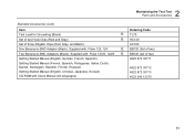
...) Getting Started Manual (English, Chinese, Japanese, Korean) CD-ROM with : Fluke 123, 124 Two Banana-to -BNC Adapter (Black). Standard Accessories (cont) Item Test Lead for Grounding (Black) Set of two Hook Clips (Red and Gray) Set of two) 4822 872 30711 4822 872 30712 4822 872 30713 4022 240 12370 51 Supplied with Users Manual (All languages) 2 Maintaining the Test Tool Parts and Accessories Ordering Code TL75...
...) Getting Started Manual (English, Chinese, Japanese, Korean) CD-ROM with : Fluke 123, 124 Two Banana-to -BNC Adapter (Black). Standard Accessories (cont) Item Test Lead for Grounding (Black) Set of two Hook Clips (Red and Gray) Set of two) 4822 872 30711 4822 872 30712 4822 872 30713 4022 240 12370 51 Supplied with Users Manual (All languages) 2 Maintaining the Test Tool Parts and Accessories Ordering Code TL75...
FE 123 & 124 Users Manual
Page 60
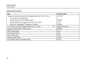
... Windows® 10:1 Scope Probe VP40. Hard Carrying Case. Supplied with Fluke 123/S, 124/S) Set contains the following parts: Optically Isolated RS-232 Adapter/Cable Hard Carrying Case. Supplied with Fluke 123/S, 124/S FlukeView® ScopeMeter® Software for Parallel Printers Ordering Code SCC 120 PM9080 C120 SW90W VPS40 (Set of two) PM9080 C120 C125 C789 ITP120 PAC91 52 Fluke 123/124 Users Manual Optional Accessories Item Software & Cable Carrying Case Kit (Supplied...
... Windows® 10:1 Scope Probe VP40. Hard Carrying Case. Supplied with Fluke 123/S, 124/S) Set contains the following parts: Optically Isolated RS-232 Adapter/Cable Hard Carrying Case. Supplied with Fluke 123/S, 124/S FlukeView® ScopeMeter® Software for Parallel Printers Ordering Code SCC 120 PM9080 C120 SW90W VPS40 (Set of two) PM9080 C120 C125 C789 ITP120 PAC91 52 Fluke 123/124 Users Manual Optional Accessories Item Software & Cable Carrying Case Kit (Supplied...
FE 123 & 124 Users Manual
Page 63
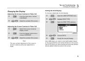
... Troubleshooting Changing the Display Setting the Grid Display To choose a dotted grid, do the following: Open the USER OPTIONS menu. Highlight GRID TYPE. Accept the new grid display. Note The new contrast adjustment of the screen. Open the GRID TYPE submenu. Use DOTS when you need vertical and horizontal division dots as added reference points to display control. Choose DOTS. Adjusting the Screen Contrast in Fluke 123 From the main menu...
... Troubleshooting Changing the Display Setting the Grid Display To choose a dotted grid, do the following: Open the USER OPTIONS menu. Highlight GRID TYPE. Accept the new grid display. Note The new contrast adjustment of the screen. Open the GRID TYPE submenu. Use DOTS when you need vertical and horizontal division dots as added reference points to display control. Choose DOTS. Adjusting the Screen Contrast in Fluke 123 From the main menu...
FE 123 & 124 Users Manual
Page 66
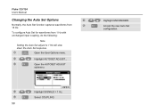
Open the User Options menu. Highlight AUTOSET ADJUST... To configure Auto Set for waveforms from 15 Hz. Open the AUTOSET ADJUST submenu. Highlight SIGNALS > 1 Hz. Accept the new Auto Set configuration. Fluke 123/124 Users Manual Changing the Auto Set Options Normally, the Auto Set function captures waveforms from 1 Hz with unchanged input coupling, do the following: Note Setting the Auto Set adjust to 1 Hz will slow down the Auto Set response. Select COUPLING. 58 Highlight UNCHANGED.
Open the User Options menu. Highlight AUTOSET ADJUST... To configure Auto Set for waveforms from 15 Hz. Open the AUTOSET ADJUST submenu. Highlight SIGNALS > 1 Hz. Accept the new Auto Set configuration. Fluke 123/124 Users Manual Changing the Auto Set Options Normally, the Auto Set function captures waveforms from 1 Hz with unchanged input coupling, do the following: Note Setting the Auto Set adjust to 1 Hz will slow down the Auto Set response. Select COUPLING. 58 Highlight UNCHANGED.
FE 123 & 124 Users Manual
Page 77
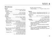
... isolated RS-232 adapter/cable, optional). Miscellaneous Display Size 72 x 72 mm (2.83 x 2.83 in) Resolution 240 x 240 pixels Waveform Display: Vertical 8 div of 20 pixels Horizontal 9.6 div of 25 pixels Backlight Cold Cathode Fluorescent (CCFL) Power External via Power Adapter PM8907 Input Voltage 10 to 21V DC Power 5W typical Input Connector 5 mm jack Fluke 123 (Internal Battery Pack BP120): Battery Power Rechargeable Ni-Cd 4.8V Operating Time 4 hours with...
... isolated RS-232 adapter/cable, optional). Miscellaneous Display Size 72 x 72 mm (2.83 x 2.83 in) Resolution 240 x 240 pixels Waveform Display: Vertical 8 div of 20 pixels Horizontal 9.6 div of 25 pixels Backlight Cold Cathode Fluorescent (CCFL) Power External via Power Adapter PM8907 Input Voltage 10 to 21V DC Power 5W typical Input Connector 5 mm jack Fluke 123 (Internal Battery Pack BP120): Battery Power Rechargeable Ni-Cd 4.8V Operating Time 4 hours with...

FE 123 & 124 Users Manual
Page 85
... Recalling, 32 Recalling Screens and Setups, 33 Record a Waveform, 21 Recording Slow Signals, 25 Red INPUT A, 12 Refreshing the Batteries, 49 Relative Measurements, 17 Replaceable Parts, 49 Replacing Batteries, 46 Resetting, 54 Resetting the Test Tool, 8 Reversing the Polarity, 26 Rise Time, 62 Rise Time Measurements, 37 Roll Mode Function, 25 77 Floating Voltage, 6, 62, 70 Max. Input Voltage, 62, 70 Maximum (MAX) Reading, 23 Measurement Connections, 12 Measurements...
... Recalling, 32 Recalling Screens and Setups, 33 Record a Waveform, 21 Recording Slow Signals, 25 Red INPUT A, 12 Refreshing the Batteries, 49 Relative Measurements, 17 Replaceable Parts, 49 Replacing Batteries, 46 Resetting, 54 Resetting the Test Tool, 8 Reversing the Polarity, 26 Rise Time, 62 Rise Time Measurements, 37 Roll Mode Function, 25 77 Floating Voltage, 6, 62, 70 Max. Input Voltage, 62, 70 Maximum (MAX) Reading, 23 Measurement Connections, 12 Measurements...


