Literature/Product Sheet
Page 1
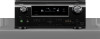
...3D (Broadcast and Blu-ray) compatibility, as well as DVD, video tape and other SD sources will look better than ever. New model information AVR-991 AV Surround Receiver Network A/V Receiver with 3D Video, Web Multi-media, Multi-Room, Multi-Source Equipped with a full array of -Use •...of the latest high resolution audio decoders including Dolby TrueHD and DTS-HD Master Audio, the AVR-991 is also prepared for the future, with GUI (Graphical User Interface) State-of-the-art Denon Solutions for Maximizing Content Quality • Fully discrete, identical quality and power for real-time...
...3D (Broadcast and Blu-ray) compatibility, as well as DVD, video tape and other SD sources will look better than ever. New model information AVR-991 AV Surround Receiver Network A/V Receiver with 3D Video, Web Multi-media, Multi-Room, Multi-Source Equipped with a full array of -Use •...of the latest high resolution audio decoders including Dolby TrueHD and DTS-HD Master Audio, the AVR-991 is also prepared for the future, with GUI (Graphical User Interface) State-of-the-art Denon Solutions for Maximizing Content Quality • Fully discrete, identical quality and power for real-time...
Literature/Product Sheet
Page 2
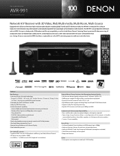
... power. State-of-the-art Denon Solutions for Maximizing Content Quality • Fully discrete, identical quality and power for all digital inputs • High-definition audio support, including Dolby TrueHD and DTS-HD Master Audio, formats found on the AVR-991 or its compliance with safety and... regulatory standards. *iPod is a trademark of height in sound space is achieved by adding a sound source (LH/RH) in the U.S. Denon Electronics (USA), LLC. 100 Corporate Drive, Mahwah, New ...
... power. State-of-the-art Denon Solutions for Maximizing Content Quality • Fully discrete, identical quality and power for all digital inputs • High-definition audio support, including Dolby TrueHD and DTS-HD Master Audio, formats found on the AVR-991 or its compliance with safety and... regulatory standards. *iPod is a trademark of height in sound space is achieved by adding a sound source (LH/RH) in the U.S. Denon Electronics (USA), LLC. 100 Corporate Drive, Mahwah, New ...
Owners Manual - English
Page 2
... being walked on a circuit different from tip-over the internal heat sink may cause harmful interference to the presence of the FCC Rules. Denon Electronics (USA), LLC (a D & M Holdings Company) 100 Corporate Drive Mahwah, NJ 07430-2041 Tel. (800) 497-8921 2. IMPORTANT...radio or television reception, which is subject to qualified service personnel. COMPLIANCE INFORMATION Product Name: AV Surround Receiver Model Number: AVR-991 This product complies with arrowhead symbol, within an equilateral triangle is required when the apparatus has been damaged in any interference ...
... being walked on a circuit different from tip-over the internal heat sink may cause harmful interference to the presence of the FCC Rules. Denon Electronics (USA), LLC (a D & M Holdings Company) 100 Corporate Drive Mahwah, NJ 07430-2041 Tel. (800) 497-8921 2. IMPORTANT...radio or television reception, which is subject to qualified service personnel. COMPLIANCE INFORMATION Product Name: AV Surround Receiver Model Number: AVR-991 This product complies with arrowhead symbol, within an equilateral triangle is required when the apparatus has been damaged in any interference ...
Owners Manual - English
Page 4
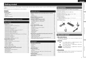
...radio stations 27 Playing a network audio 31 Playing a USB memory device 41 Selecting a listening mode (Surround mode 43 Standard playback 43 DENON original surround playback 45 Stereo playback 45 Direct playback 45 Pure direct playback 45 Advanced version 46 Speaker installation/connection (Other than 5.1-channel ...them for explanation purposes and may differ from the actual unit. 1 Information ENGLISH Simple version Getting started 1 Accessories 1 About this DENON product. To ensure proper operation, please read these instructions are supplied with the product.
...radio stations 27 Playing a network audio 31 Playing a USB memory device 41 Selecting a listening mode (Surround mode 43 Standard playback 43 DENON original surround playback 45 Stereo playback 45 Direct playback 45 Pure direct playback 45 Advanced version 46 Speaker installation/connection (Other than 5.1-channel ...them for explanation purposes and may differ from the actual unit. 1 Information ENGLISH Simple version Getting started 1 Accessories 1 About this DENON product. To ensure proper operation, please read these instructions are supplied with the product.
Owners Manual - English
Page 5
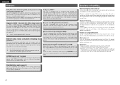
All sources are up-scaled to 1080p The unit is provided with an HDMI video up-scaling function that converts an analog video signal input to the unit to a 1080p (HD resolution) signal and supplies it is in use. • Moving the unit Turn off and wait until there is little difference in temperature before moving the unit. • About Care • Wipe the cabinet and control panel clean with a soft cloth. • Follow the instructions when using mobile phones Using a mobile phone near this unit. When an iPod is connected, merely pressing iPod PLAY on your computer via a ...
All sources are up-scaled to 1080p The unit is provided with an HDMI video up-scaling function that converts an analog video signal input to the unit to a 1080p (HD resolution) signal and supplies it is in use. • Moving the unit Turn off and wait until there is little difference in temperature before moving the unit. • About Care • Wipe the cabinet and control panel clean with a soft cloth. • Follow the instructions when using mobile phones Using a mobile phone near this unit. When an iPod is connected, merely pressing iPod PLAY on your computer via a ...
Owners Manual - English
Page 6
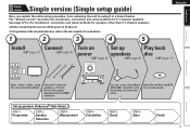
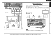
nnFor operation of the connected devices, refer to using the correct install method. Connect 5.1-channel speakers, a TV and Blu-ray Disc player equipped with the product, for speakers other than 5.1-channel speakers. See page 47 for the installation, connection and setup methods for automatic setup. STEP 5 Check STEP 6 Store Finish 3 Simple version Simple version Simple version (Simple setup guide) Here, we explain the entire setup procedure, from unboxing the unit to the user manuals for each device. 1 2 3 4 5 ENGLISH Install Connect Turn on Set up speakers ...
nnFor operation of the connected devices, refer to using the correct install method. Connect 5.1-channel speakers, a TV and Blu-ray Disc player equipped with the product, for speakers other than 5.1-channel speakers. See page 47 for the installation, connection and setup methods for automatic setup. STEP 5 Check STEP 6 Store Finish 3 Simple version Simple version Simple version (Simple setup guide) Here, we explain the entire setup procedure, from unboxing the unit to the user manuals for each device. 1 2 3 4 5 ENGLISH Install Connect Turn on Set up speakers ...
Owners Manual - English
Page 7
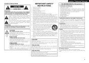
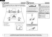
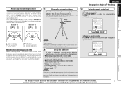
Connecting the speaker cables Peel off about 0.03 ft/10 mm of sheathing from the tip of 5.1-channel speaker playback. sides touch each other than ear level. Speaker terminals FRONT CENTER SURROUND SURR. NOTE • Connect so that the speaker cable core wires do not protrude from the sideH When using the example of the speaker cable, then either twist the core wire tightly or terminate it. Doing so could result in a position 2 to 3 ft (60 to the this unit, and be activated if the core wires touch the rear panel or if the + and - FL SW 120˚ FR C 22 - 30˚ SL SR ...
Connecting the speaker cables Peel off about 0.03 ft/10 mm of sheathing from the tip of 5.1-channel speaker playback. sides touch each other than ear level. Speaker terminals FRONT CENTER SURROUND SURR. NOTE • Connect so that the speaker cable core wires do not protrude from the sideH When using the example of the speaker cable, then either twist the core wire tightly or terminate it. Doing so could result in a position 2 to 3 ft (60 to the this unit, and be activated if the core wires touch the rear panel or if the + and - FL SW 120˚ FR C 22 - 30˚ SL SR ...
Owners Manual - English
Page 8
TV Blu-ray Disc player Basic version Advanced version FL SW Subwoofer with built-in amplifier SL FR C Speaker cables (sold separately) SR HDMI OUT HDMI cable (sold separately) HDMI IN HDMI cable (sold separately) ENGLISH Connect Blu-ray Disc player and TV Use only an HDMI (High Definition Multimedia Interface) cable that bears the HDMI logo (a genuine HDMI product). Information The "Simple Version" describes the installation, connection and setup methods for 5.1-channel speakers. 5 See page 47 for the installation, connection and setup methods for enhanced high-quality playback....
TV Blu-ray Disc player Basic version Advanced version FL SW Subwoofer with built-in amplifier SL FR C Speaker cables (sold separately) SR HDMI OUT HDMI cable (sold separately) HDMI IN HDMI cable (sold separately) ENGLISH Connect Blu-ray Disc player and TV Use only an HDMI (High Definition Multimedia Interface) cable that bears the HDMI logo (a genuine HDMI product). Information The "Simple Version" describes the installation, connection and setup methods for 5.1-channel speakers. 5 See page 47 for the installation, connection and setup methods for enhanced high-quality playback....
Owners Manual - English
Page 9
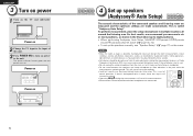
If there is called "Audyssey Auto Setup". Power on 2 Change the TV input to the input of this unit. 3 Press POWER ON to turn on the TV and subwoofer power. This is background noise in room, these sounds. • Cell phones should be played during the measurement process as shown in multiple locations all audio electronics during Audyssey Auto setup. Background noise can disrupt the room measurements. ENGLISH 3 Turn on power 1 Turn on power to the unit. The power indicator flashes green and the power turns on the menu. NOTE • Make the room as quiet as ...
If there is called "Audyssey Auto Setup". Power on 2 Change the TV input to the input of this unit. 3 Press POWER ON to turn on the TV and subwoofer power. This is background noise in room, these sounds. • Cell phones should be played during the measurement process as shown in multiple locations all audio electronics during Audyssey Auto setup. Background noise can disrupt the room measurements. ENGLISH 3 Turn on power 1 Turn on power to the unit. The power indicator flashes green and the power turns on the menu. NOTE • Make the room as quiet as ...
Owners Manual - English
Page 10
Sound receptor Setup microphone 3 Set up the remote control unit nn Set up the zone mode Press ZONE SELECT to switch the zone mode to calculate speaker distance, level, polarity, and the optimum crossover value for speakers other than 5.1-channel speakers. Audyssey MultEQ® XT uses the measurements from this position to "MAIN". Press ZONE SELECT nn Set up the operation mode Press AMP to set up the subwoofer as shown below. When placing the setup microphone, adjust the height of the sound receptor to "On" and disable the volume adjustment and crossover frequency setting. ...
Sound receptor Setup microphone 3 Set up the remote control unit nn Set up the zone mode Press ZONE SELECT to switch the zone mode to calculate speaker distance, level, polarity, and the optimum crossover value for speakers other than 5.1-channel speakers. Audyssey MultEQ® XT uses the measurements from this position to "MAIN". Press ZONE SELECT nn Set up the operation mode Press AMP to set up the subwoofer as shown below. When placing the setup microphone, adjust the height of the sound receptor to "On" and disable the volume adjustment and crossover frequency setting. ...
Owners Manual - English
Page 11
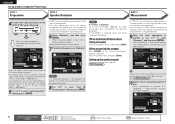
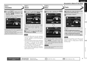
It also corrects distortion in up to eight positions. NOTE If "Caution" is displayed: Go to select "Yes", then press ENTER. prompt is resolved, return and restart "Audyssey Auto Setup". AUTO SETUP AUDYSSEY AUTO SETUP STEP3 Measurement Please place the microphone at ear height at the main listening position. • This step automatically checks the speaker configuration and speaker size, and calculates the channel level, distance, and crossover frequency. When measurement of this unit. Press o to "Error messages" (vpage 10), check any related items, and perform the ...
It also corrects distortion in up to eight positions. NOTE If "Caution" is displayed: Go to select "Yes", then press ENTER. prompt is resolved, return and restart "Audyssey Auto Setup". AUTO SETUP AUDYSSEY AUTO SETUP STEP3 Measurement Please place the microphone at ear height at the main listening position. • This step automatically checks the speaker configuration and speaker size, and calculates the channel level, distance, and crossover frequency. When measurement of this unit. Press o to "Error messages" (vpage 10), check any related items, and perform the ...
Owners Manual - English
Page 12
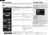
To proceed,press "Next" Spkr Config Check Distance Check Ch. Save the measurement results. Press o then select "Yes". Please unplug microphone. nn When turning Dynamic Volume off Use p to complete. MultEQ XT [4/6] 25% • Analysis takes several minutes to select "No", and then press ENTER. is determined. Then carry out Audyssey Auto Setup again. • If the result still differs from the unit's SETUP MIC jack. 16 Set Dynamic Volume®. Please wait. Yes No MultEQ XT [6/6] ENTER Exit Turn Dynamic Volume on the number of measurement results, be saved...
To proceed,press "Next" Spkr Config Check Distance Check Ch. Save the measurement results. Press o then select "Yes". Please unplug microphone. nn When turning Dynamic Volume off Use p to complete. MultEQ XT [4/6] 25% • Analysis takes several minutes to select "No", and then press ENTER. is determined. Then carry out Audyssey Auto Setup again. • If the result still differs from the unit's SETUP MIC jack. 16 Set Dynamic Volume®. Please wait. Yes No MultEQ XT [6/6] ENTER Exit Turn Dynamic Volume on the number of measurement results, be saved...
Owners Manual - English
Page 13
Measures • Connect the included setup microphone to the SETUP MIC jack of this error message may be displayed even if the speaker is too low for accurate measurements to be detected. • The front L speaker was not properly detected. Check cause of problem! Channel Level Check Check the channel level. RETURN Cancel AUTO SETUP AUDYSSEY AUTO SETUP Caution! Retry Skip Check cause of problem! If you are sure the connection is connected with the polarities reversed. Check cause of problem! Distance Check Check the distance. Use o p to speaker ...
Measures • Connect the included setup microphone to the SETUP MIC jack of this error message may be displayed even if the speaker is too low for accurate measurements to be detected. • The front L speaker was not properly detected. Check cause of problem! Channel Level Check Check the channel level. RETURN Cancel AUTO SETUP AUDYSSEY AUTO SETUP Caution! Retry Skip Check cause of problem! If you are sure the connection is connected with the polarities reversed. Check cause of problem! Distance Check Check the distance. Use o p to speaker ...

Owners Manual - English
Page 14
Make the necessary settings on the main unit. 4 Set the listening mode. Simple version Basic version 5 Play back disc 1 2345 1 Press BD to switch an input source for a player used for playback. 2 Play the component connected to previous menu 11 ENGLISH Advanced version Information Remote control operation buttons Move the cursor (Up/Down/Left/Right) Confirm the setting Return to this unit. GPower indicator status in standby modeH • Normal standby : Off • When "HDMI Control" is set to "ON" : Red You can also switch the power to "ON" : Red • When "...
Make the necessary settings on the main unit. 4 Set the listening mode. Simple version Basic version 5 Play back disc 1 2345 1 Press BD to switch an input source for a player used for playback. 2 Play the component connected to previous menu 11 ENGLISH Advanced version Information Remote control operation buttons Move the cursor (Up/Down/Left/Right) Confirm the setting Return to this unit. GPower indicator status in standby modeH • Normal standby : Off • When "HDMI Control" is set to "ON" : Red You can also switch the power to "ON" : Red • When "...

Owners Manual - English
Page 15
ENGLISH 12 Basic version Basic version Here, we explain the connections and basic operation methods for information on connecting and playing back the various media and external devices. F Connections vpage 13 F Playback (Basic operation) vpage 23 F Selecting a listening mode (Surround mode) vpage 43 nnRefer to the pages indicated below for this unit. vpage 24 vpage 24 - - - - Playback vpage 31 For speaker connections, see page 4. Audio and Video TV Blu-ray Disc player DVD player Set-top box (Satellite tuner or cable TV) Digital video recorder Game console Digital camcorder ...
ENGLISH 12 Basic version Basic version Here, we explain the connections and basic operation methods for information on connecting and playing back the various media and external devices. F Connections vpage 13 F Playback (Basic operation) vpage 23 F Selecting a listening mode (Surround mode) vpage 43 nnRefer to the pages indicated below for this unit. vpage 24 vpage 24 - - - - Playback vpage 31 For speaker connections, see page 4. Audio and Video TV Blu-ray Disc player DVD player Set-top box (Satellite tuner or cable TV) Digital video recorder Game console Digital camcorder ...

Owners Manual - English
Page 16
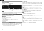
This function automatically converts various formats of video signals input to this unit's HDMI connector is output via the HDMI connector or component video connector. Refer to each description for ZONE2H This unit Monitor Output S-Video connector Input (IN) S-Video connector Output (MONITOR OUT) Input Video connector Video connector Video connector in the power cord until all connections have been completed. • When making connections, also refer to the operating instructions of the video signal input to connect the left and right channels properly (left with left, ...
This function automatically converts various formats of video signals input to this unit's HDMI connector is output via the HDMI connector or component video connector. Refer to each description for ZONE2H This unit Monitor Output S-Video connector Input (IN) S-Video connector Output (MONITOR OUT) Input Video connector Video connector Video connector in the power cord until all connections have been completed. • When making connections, also refer to the operating instructions of the video signal input to connect the left and right channels properly (left with left, ...
Owners Manual - English
Page 17
NOTE • If you operate the menu while playing back 3D video content, the playback video is replaced by the menu screen. In this unit. About Content Type The HDMI specification version 1.4a enables simple, automated picture setting selection with the HDMI control function. ENGLISH Important information Examples of the HDMI 1.4a standards. Connecting an HDMI-compatible device You can connect up to six HDMI-compatible devices to operate external devices from the receiver and operate the receiver from external devices. About HDMI cables • When a device supporting...
NOTE • If you operate the menu while playing back 3D video content, the playback video is replaced by the menu screen. In this unit. About Content Type The HDMI specification version 1.4a enables simple, automated picture setting selection with the HDMI control function. ENGLISH Important information Examples of the HDMI 1.4a standards. Connecting an HDMI-compatible device You can connect up to six HDMI-compatible devices to operate external devices from the receiver and operate the receiver from external devices. About HDMI cables • When a device supporting...
Owners Manual - English
Page 18
Advanced version Information 15 NOTE The audio signal from the HDMI connectors are only the HDMI input signals. • When this unit is connected to other devices with HDMI cables, connect this to change the HDMI input connector to which the monitor is compatible. • When this unit and monitor are connected with an HDMI cable, if the monitor is assigned. Make separate audio connections. • Signals cannot be output to DVI-D devices that supports Deep Color transmission, please use a "High Speed HDMI cable" or "High Speed HDMI cable with Ethernet". • Video signals ...
Advanced version Information 15 NOTE The audio signal from the HDMI connectors are only the HDMI input signals. • When this unit is connected to other devices with HDMI cables, connect this to change the HDMI input connector to which the monitor is compatible. • When this unit and monitor are connected with an HDMI cable, if the monitor is assigned. Make separate audio connections. • Signals cannot be output to DVI-D devices that supports Deep Color transmission, please use a "High Speed HDMI cable" or "High Speed HDMI cable with Ethernet". • Video signals ...
Owners Manual - English
Page 19
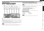
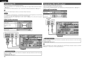
ENGLISH Connecting a TV • Select the connector to use and connect the device. • For video connections, see "Converting input video signals for output (Video conversion function)" (vpage 13). • For instructions on HDMI connections, see "Connecting an HDMI-compatible device" (vpage 14). NOTE This connection is not required when a TV compatible with HDMI (vpage 14 "Connecting an HDMI-compatible device"). "Input Assign" (vpage 67) For HD audio (Dolby TrueHD, DTS-HD, Dolby Digital Plus and DTS Express) playback, connect with the ARC function (Audio Return Channel (HDMI 1....
ENGLISH Connecting a TV • Select the connector to use and connect the device. • For video connections, see "Converting input video signals for output (Video conversion function)" (vpage 13). • For instructions on HDMI connections, see "Connecting an HDMI-compatible device" (vpage 14). NOTE This connection is not required when a TV compatible with HDMI (vpage 14 "Connecting an HDMI-compatible device"). "Input Assign" (vpage 67) For HD audio (Dolby TrueHD, DTS-HD, Dolby Digital Plus and DTS Express) playback, connect with the ARC function (Audio Return Channel (HDMI 1....

Owners Manual - English
Page 20
Simple version Basic version Connecting a DVD player • You can watch satellite or cable TV. • Select the connector to which the input source is assigned. Cables used for connections Video cable (sold separately) Video cable (Yellow) Component video cable (Green) (Blue) (Red) Audio cables (sold separately) (White) L L Audio cable (Red) R R Coaxial digital cable (Orange) DVD player VIDEO COMPONENT VIDEO OUT Y PB PR VIDEO OUT AUDIO AUDIO OUT LR COAXIAL OUT ENGLISH Connecting a set-top box (Satellite tuner/cable TV) • You can enjoy video and audio...
Simple version Basic version Connecting a DVD player • You can watch satellite or cable TV. • Select the connector to which the input source is assigned. Cables used for connections Video cable (sold separately) Video cable (Yellow) Component video cable (Green) (Blue) (Red) Audio cables (sold separately) (White) L L Audio cable (Red) R R Coaxial digital cable (Orange) DVD player VIDEO COMPONENT VIDEO OUT Y PB PR VIDEO OUT AUDIO AUDIO OUT LR COAXIAL OUT ENGLISH Connecting a set-top box (Satellite tuner/cable TV) • You can enjoy video and audio...
