
Literature/Product Sheet
Page 2
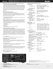
...occur when a video signal is not configured for the AVR-3803 to ensure a rock stable supply of power. ■ Newly redesigned pre-programmed remote controller with learning feature The AVR-3803 comes with a newly-developed remote controller with 110 Watts per channel output power, while ... ...... Finer adjustments are controlling at a glance. - During analog audio input, power to the digital circuitry is combined with composite video feed. DENON, LTD. 3-16-11 YUSHIMA, BUNKYO-KU, TOKYO 113-0034 JAPAN 13100902 A MONITOR 3 Composite Output VCR-1, VCR-2, MONITOR 3 S-Video Output...
...occur when a video signal is not configured for the AVR-3803 to ensure a rock stable supply of power. ■ Newly redesigned pre-programmed remote controller with learning feature The AVR-3803 comes with a newly-developed remote controller with 110 Watts per channel output power, while ... ...... Finer adjustments are controlling at a glance. - During analog audio input, power to the digital circuitry is combined with composite video feed. DENON, LTD. 3-16-11 YUSHIMA, BUNKYO-KU, TOKYO 113-0034 JAPAN 13100902 A MONITOR 3 Composite Output VCR-1, VCR-2, MONITOR 3 S-Video Output...
Owners Manual
Page 1
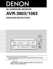
PLEASE RECORD UNIT SERIAL NUMBER ATTACHED TO THE REAR OF THE CABINET FOR FUTURE REFERENCE" "SERIAL NO. Be sure to offer, read these instructions carefully and use the set properly. AV SURROUND RECEIVER AVR-3803/1083 OPERATING INSTRUCTIONS REMOTE SENSOR ON / STANDBY AUTO SIGNAL DIGITAL SURROUND BACK CH OUTPUT INPUT PCM DTS SIGNAL DETECT VOLUME LEVEL AMP 2 We greatly appreciate your purchase of the AVR-3803/1083. 2 To be sure you take maximum advantage of all the features the AVR-3803/1083 has to keep this manual for future reference, should any questions or problems arise.
PLEASE RECORD UNIT SERIAL NUMBER ATTACHED TO THE REAR OF THE CABINET FOR FUTURE REFERENCE" "SERIAL NO. Be sure to offer, read these instructions carefully and use the set properly. AV SURROUND RECEIVER AVR-3803/1083 OPERATING INSTRUCTIONS REMOTE SENSOR ON / STANDBY AUTO SIGNAL DIGITAL SURROUND BACK CH OUTPUT INPUT PCM DTS SIGNAL DETECT VOLUME LEVEL AMP 2 We greatly appreciate your purchase of the AVR-3803/1083. 2 To be sure you take maximum advantage of all the features the AVR-3803/1083 has to keep this manual for future reference, should any questions or problems arise.
Owners Manual
Page 4
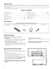
...cords between the top, back and sides of this unit and the wall or other audio components when moving the set for choosing the DENON AVR-3803/1083 Digital A / V Surround Receiver. As this product is used near a B tuner or TV. Operation 47~54 ⁄0 ...instructions.....1 w Warranty ( for North America model only 1 e Service station list...........1 t R6P/AA batteries 3 y AM loop antenna 1 u FM indoor antenna...1 r Remote control unit (RC-921 1 r t y u 1 BEFORE USING Pay attention to the following steps: • Install this unit as far as providing outstanding high ...
...cords between the top, back and sides of this unit and the wall or other audio components when moving the set for choosing the DENON AVR-3803/1083 Digital A / V Surround Receiver. As this product is used near a B tuner or TV. Operation 47~54 ⁄0 ...instructions.....1 w Warranty ( for North America model only 1 e Service station list...........1 t R6P/AA batteries 3 y AM loop antenna 1 u FM indoor antenna...1 r Remote control unit (RC-921 1 r t y u 1 BEFORE USING Pay attention to the following steps: • Install this unit as far as providing outstanding high ...

Owners Manual
Page 6
... using pin plug cords. Connecting a tape deck Connections for connection to powered loudspeakers. If this happens, turn on and standby from the remote control unit. Connecting the pre-out jacks Use these for playback: Connect the tape deck's playback output jacks (LINE OUT or PB) ...the power of the other electrical appliances. Connections for connections to audio equipment with digital output. No power is supplied from the remote control unit or power switch. Never connect equipment whose total capacity is switched between on and standby from these outlets is turned ...
... using pin plug cords. Connecting a tape deck Connections for connection to powered loudspeakers. If this happens, turn on and standby from the remote control unit. Connecting the pre-out jacks Use these for playback: Connect the tape deck's playback output jacks (LINE OUT or PB) ...the power of the other electrical appliances. Connections for connections to audio equipment with digital output. No power is supplied from the remote control unit or power switch. Never connect equipment whose total capacity is switched between on and standby from these outlets is turned ...
Owners Manual
Page 14
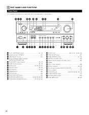
...VOLUME control 49) !9 Master volume indicator (VOLUME LEVEL 49) @0 Display @1 INPUT mode indicators 49) @2 SIGNAL indicators 49, 59) @3 Remote control sensor (REMOTE SENSOR 34) @4 Power indicator 47) @5 FUNCTION knob 48, 52, 53, 59, 61, 68, 70) @6 TUNING PRESET button 70) ...AND FUNCTIONS Front Panel • For details on the functions of these parts, refer to the pages given in parentheses ( ). @8 @7 @6 @5 @4 @3 @2 @1 @0 !9 REMOTE SENSOR ON / STANDBY AUTO SIGNAL DIGITAL SURROUND BACK CH OUTPUT INPUT PCM DTS SIGNAL DETECT VOLUME LEVEL !8 q w er t y u i o !0 !1 !2 !3 !4 !5 !6...
...VOLUME control 49) !9 Master volume indicator (VOLUME LEVEL 49) @0 Display @1 INPUT mode indicators 49) @2 SIGNAL indicators 49, 59) @3 Remote control sensor (REMOTE SENSOR 34) @4 Power indicator 47) @5 FUNCTION knob 48, 52, 53, 59, 61, 68, 70) @6 TUNING PRESET button 70) ...AND FUNCTIONS Front Panel • For details on the functions of these parts, refer to the pages given in parentheses ( ). @8 @7 @6 @5 @4 @3 @2 @1 @0 !9 REMOTE SENSOR ON / STANDBY AUTO SIGNAL DIGITAL SURROUND BACK CH OUTPUT INPUT PCM DTS SIGNAL DETECT VOLUME LEVEL !8 q w er t y u i o !0 !1 !2 !3 !4 !5 !6...
Owners Manual
Page 15
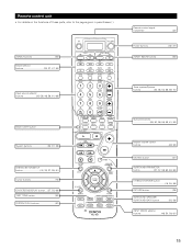
ZONE 2 buttons 53) Mode selector buttons 35, 37, 47, 53) Input source selector buttons 35~38, 48, 59, 61, 68) Remote control signal transmitter 34) Power buttons 36~47) ZONE1 (MAIN) buttons 53) Tuner system/System buttons 35, 38, 53, 68, 69, 70) BACK LIGHT button ... SELECT/ENTER button 16, 55, 56) RETURN button 38) SURROUND SPEAKER/ SURROUND BACK button 52, 59) INPUT MODE selector buttons 48, 50, 59, 61) 15 Remote control unit • For details on the functions of these parts, refer to the pages given in parentheses ( ).
ZONE 2 buttons 53) Mode selector buttons 35, 37, 47, 53) Input source selector buttons 35~38, 48, 59, 61, 68) Remote control signal transmitter 34) Power buttons 36~47) ZONE1 (MAIN) buttons 53) Tuner system/System buttons 35, 38, 53, 68, 69, 70) BACK LIGHT button ... SELECT/ENTER button 16, 55, 56) RETURN button 38) SURROUND SPEAKER/ SURROUND BACK button 52, 59) INPUT MODE selector buttons 48, 50, 59, 61) 15 Remote control unit • For details on the functions of these parts, refer to the pages given in parentheses ( ).
Owners Manual
Page 16
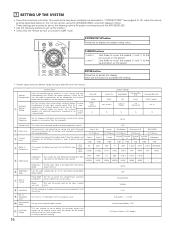
These settings are operated. Use this function when using the AVR-3803/1083's on the monitor screen using multiple surround speaker combinations for playing deep bass ...cursors (F and G) to the left and right on the remote control unit or main unit are required to set up the listening room's AV system centered around the AVR-3803/1083. • Use the following buttons to set up and... Dolby Digital Setup Turn the audio compression on or off when down on -screen display that the remote control unit is to be used for the different surround modes are preset, the surround speakers are...
These settings are operated. Use this function when using the AVR-3803/1083's on the monitor screen using multiple surround speaker combinations for playing deep bass ...cursors (F and G) to the left and right on the remote control unit or main unit are required to set up the listening room's AV system centered around the AVR-3803/1083. • Use the following buttons to set up and... Dolby Digital Setup Turn the audio compression on or off when down on -screen display that the remote control unit is to be used for the different surround modes are preset, the surround speakers are...

Owners Manual
Page 22
... the listening position, listen to the test tones produced from the speakers to adjust the level. • The level can be adjusted directly from the remote control unit. (For details, see page 16, 17). 6 Set the distance between the different channels is set, the settings are automatically reset to the default... is set an invalid distance, a CAUTION notice, such as screen right will appear. Select the value closest to 12 feet for the listening room. The AVR-3803/1083 automatically sets the optimum surround delay time for the center speaker If "Yes" is pressed.
... the listening position, listen to the test tones produced from the speakers to adjust the level. • The level can be adjusted directly from the remote control unit. (For details, see page 16, 17). 6 Set the distance between the different channels is set, the settings are automatically reset to the default... is set an invalid distance, a CAUTION notice, such as screen right will appear. Select the value closest to 12 feet for the listening room. The AVR-3803/1083 automatically sets the optimum surround delay time for the center speaker If "Yes" is pressed.

Owners Manual
Page 28
... in the analog input direct mode or stereo mode (T0NE DEFEAT "ON"). 28 Select "Zone2 Vol. The System Setup Menu reappears. For instructions on the remote control unit. 0 dB, -40 dB: The output level is fixed at the set level and the volume can be adjusted. 4 Enter the setting. The System...
... in the analog input direct mode or stereo mode (T0NE DEFEAT "ON"). 28 Select "Zone2 Vol. The System Setup Menu reappears. For instructions on the remote control unit. 0 dB, -40 dB: The output level is fixed at the set level and the volume can be adjusted. 4 Enter the setting. The System...
Owners Manual
Page 34
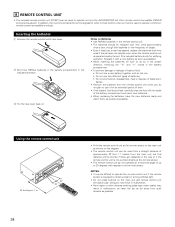
... feet/Approx. 7 m 30° 30° 34 • Point the remote control unit at the remote sensor on the main unit as shown on the diagram. • The remote control unit can be used to operate not only the AVR-3803/1083 but this distance will be shorter if there are obstacles in...emitting pulse-type noise nearby may result in malfunction. • Neon signs or other remote control compatible DENON components as well. Doing so may result in the indicated direction. 8 REMOTE CONTROL UNIT • The included remote control unit (RC-921) can be sure to do not plan to use two different...
... feet/Approx. 7 m 30° 30° 34 • Point the remote control unit at the remote sensor on the main unit as shown on the diagram. • The remote control unit can be used to operate not only the AVR-3803/1083 but this distance will be shorter if there are obstacles in...emitting pulse-type noise nearby may result in malfunction. • Neon signs or other remote control compatible DENON components as well. Doing so may result in the indicated direction. 8 REMOTE CONTROL UNIT • The included remote control unit (RC-921) can be sure to do not plan to use two different...
Owners Manual
Page 36
... are pressed. For example, when the MD mode is deleted, only the CDR mode is displayed when the CDR/MD button is listed on the remote control unit, then press the ENTER button. The display switches as follows upon shipment from the factory and after resetting: TV, VCR1 HITACHI CD, MD..., TAPE, CDR, VDP, DVD DENON VCR2, DBS SONY CABLE ABC 36 Refer to the included list of preset codes to store in the memory, repeat steps 1 to 5. Use the •...
... are pressed. For example, when the MD mode is deleted, only the CDR mode is displayed when the CDR/MD button is listed on the remote control unit, then press the ENTER button. The display switches as follows upon shipment from the factory and after resetting: TV, VCR1 HITACHI CD, MD..., TAPE, CDR, VDP, DVD DENON VCR2, DBS SONY CABLE ABC 36 Refer to the included list of preset codes to store in the memory, repeat steps 1 to 5. Use the •...

Owners Manual
Page 37
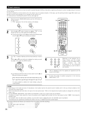
... component. • For details, refer to manufacturer. NOTE: • For the DVD player remote control buttons, function names may differ according to the component's operating instructions. Compare with this remote control unit. 1. Digital video disc player (DVD, DVD SETUP) system buttons POWER : Power ...) 6,7 : Manual search (forward and reverse) 2 : Stop 1 : Play 8,9 : Auto search (to operate. Some models cannot be operated with the remote control operation of track) 3 : Pause 0 ~ 9, +10 : 10 key DISC SKIP +: Disc skip (for the component you want to beginning of the...
... component. • For details, refer to manufacturer. NOTE: • For the DVD player remote control buttons, function names may differ according to the component's operating instructions. Compare with this remote control unit. 1. Digital video disc player (DVD, DVD SETUP) system buttons POWER : Power ...) 6,7 : Manual search (forward and reverse) 2 : Stop 1 : Play 8,9 : Auto search (to operate. Some models cannot be operated with the remote control operation of track) 3 : Pause 0 ~ 9, +10 : 10 key DISC SKIP +: Disc skip (for the component you want to beginning of the...
Owners Manual
Page 39
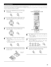
... 8 To cancel the learning mode, press the power ON/SOURCE button and the OFF button simultaneously again. Other remote control unit 39 Other keys can be "learned" by repeating steps 4 to 6. 7 The mode can be ...remote control unit's display and learning is completed. • "KEY" is displayed. Registering is not possible in the button on the other and press and hold in the receiver mode. Learning function If your AV component is not a Denon... product or if it cannot be operated using the preset memory, it can be switched by storing its remote control signals in the...
... 8 To cancel the learning mode, press the power ON/SOURCE button and the OFF button simultaneously again. Other remote control unit 39 Other keys can be "learned" by repeating steps 4 to 6. 7 The mode can be ...remote control unit's display and learning is completed. • "KEY" is displayed. Registering is not possible in the button on the other and press and hold in the receiver mode. Learning function If your AV component is not a Denon... product or if it cannot be operated using the preset memory, it can be switched by storing its remote control signals in the...
Owners Manual
Page 40
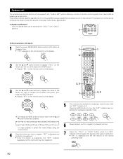
... while the "KEY" indicator is lit to register the signals at the system call button, then press the ENTER button. • Display "KEY" on the remote control unit's display. 2, 3 7 2, 3 5 The mode can be stored at the "CALL1" and "CALL2" buttons. 1 (2) Storing system call signals 1 Press the power ON/SOURCE .... • "OK" is displayed and the set the source to the play mode, all at a signal button. (1) System call " function allowing a series of remote control signals to be transmitted by pressing a mode button while the "KEY" indicator is lit. System call The accessorious...
... while the "KEY" indicator is lit to register the signals at the system call button, then press the ENTER button. • Display "KEY" on the remote control unit's display. 2, 3 7 2, 3 5 The mode can be stored at the "CALL1" and "CALL2" buttons. 1 (2) Storing system call signals 1 Press the power ON/SOURCE .... • "OK" is displayed and the set the source to the play mode, all at a signal button. (1) System call " function allowing a series of remote control signals to be transmitted by pressing a mode button while the "KEY" indicator is lit. System call The accessorious...
Owners Manual
Page 41
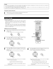
... CDR MD TAPE DVD VCR2 VCR1 VDP It is also possible to select the mode directly using the mode buttons. NOTES: • The remote control signals of the buttons pressed while registering the system call signals are emitted, so be careful not to operate the components accidentally (cover ... the • and ª cursor buttons to display the mode you exceed the number of signals that can be registered, "FULL" appears on the remote control unit's display and only the number of signals that can be registered are registered (up to 10 operations). (3) Using the system call function 1 ...
... CDR MD TAPE DVD VCR2 VCR1 VDP It is also possible to select the mode directly using the mode buttons. NOTES: • The remote control signals of the buttons pressed while registering the system call signals are emitted, so be careful not to operate the components accidentally (cover ... the • and ª cursor buttons to display the mode you exceed the number of signals that can be registered, "FULL" appears on the remote control unit's display and only the number of signals that can be registered are registered (up to 10 operations). (3) Using the system call function 1 ...
Owners Manual
Page 42
... unit's display. 2 Use the • and ª cursor buttons to display "BKLT" on the remote control unit, then press the ENTER button. • "05SEC" appears on the remote control unit's display. 3 Use the • and ª cursor buttons to adjust the lighting time (3 sec ~ 30 sec), then press the ENTER button. •... 1 DVD 1 2, 3 2, 3 Resetting (1) Resetting the preset memory 1 Press the power ON/SOURCE button and the OFF button at the same time. • "PRE" appears on the remote control unit's display. 2 Use the • and ª cursor buttons to display "RST" on the...
... unit's display. 2 Use the • and ª cursor buttons to display "BKLT" on the remote control unit, then press the ENTER button. • "05SEC" appears on the remote control unit's display. 3 Use the • and ª cursor buttons to adjust the lighting time (3 sec ~ 30 sec), then press the ENTER button. •... 1 DVD 1 2, 3 2, 3 Resetting (1) Resetting the preset memory 1 Press the power ON/SOURCE button and the OFF button at the same time. • "PRE" appears on the remote control unit's display. 2 Use the • and ª cursor buttons to display "RST" on the...
Owners Manual
Page 43
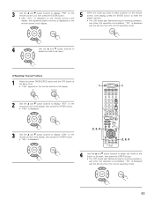
...power ON/SOURCE button and the OFF button at the same time. • "PRE" appears on the remote control unit's display. 2 Use the • and ª cursor buttons to display "RST" on the remote control unit's display, then press the ENTER button. • "PRE" is displayed. 1 DVD 1 3... Use the • and ª cursor buttons to display "LRN" on the remote control unit's display, then press the ENTER button. • "SEL" is displayed. 2, 3, 4 2, 3, 4 4 Use the • and ª cursor buttons to ...
...power ON/SOURCE button and the OFF button at the same time. • "PRE" appears on the remote control unit's display. 2 Use the • and ª cursor buttons to display "RST" on the remote control unit's display, then press the ENTER button. • "PRE" is displayed. 1 DVD 1 3... Use the • and ª cursor buttons to display "LRN" on the remote control unit's display, then press the ENTER button. • "SEL" is displayed. 2, 3, 4 2, 3, 4 4 Use the • and ª cursor buttons to ...
Owners Manual
Page 44
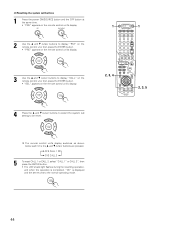
... the same time. • "PRE" appears on the remote control unit's display. 2 Use the • and ª cursor buttons to display "RST" on the remote control unit, then press the ENTER button. • "PRE" appears on the remote control unit's display. 1 DVD 1 3 Use the &#...8226; and ª cursor buttons to display "CALL" on the remote control unit, then press the ENTER button. • "SEL" appears on the remote control unit's display. 2, 3, 4 2, 3, 5 4 Press the...
... the same time. • "PRE" appears on the remote control unit's display. 2 Use the • and ª cursor buttons to display "RST" on the remote control unit, then press the ENTER button. • "PRE" appears on the remote control unit's display. 1 DVD 1 3 Use the &#...8226; and ª cursor buttons to display "CALL" on the remote control unit, then press the ENTER button. • "SEL" appears on the remote control unit's display. 2, 3, 4 2, 3, 5 4 Press the...
Owners Manual
Page 45
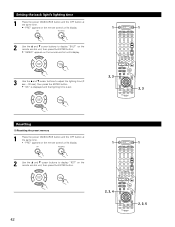
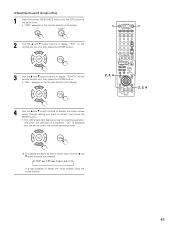
...power ON/SOURCE button and the OFF button at the same time. • "PRE" appears on the remote control unit's display. 2 Use the • and ª cursor buttons to display "RST" on the remote control unit, then press the ENTER button. 1 DVD 1 3 Use the • and ª ...cursor buttons to display "PUNCH" on the remote control unit, then press the ENTER button. • "SEL" appears on the remote control unit's display. 2, 3, 4 4 Use the • and ª cursor buttons to display the mode whose punch through...
...power ON/SOURCE button and the OFF button at the same time. • "PRE" appears on the remote control unit's display. 2 Use the • and ª cursor buttons to display "RST" on the remote control unit, then press the ENTER button. 1 DVD 1 3 Use the • and ª ...cursor buttons to display "PUNCH" on the remote control unit, then press the ENTER button. • "SEL" appears on the remote control unit's display. 2, 3, 4 4 Use the • and ª cursor buttons to display the mode whose punch through...
Owners Manual
Page 46
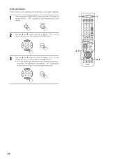
.... 1 Press the power ON/SOURCE button and the OFF button at the same time. "PRE" appears on the remote control unit's display. 2 Use the • and ª cursor buttons to display "RST" on the remote control unit, then press the ENTER button. 3 Use the • and ª cursor buttons to display "ALL..." on the remote control unit, then press the ENTER button. • The LCD's back light flashes during the resetting operation, and when the operation is completed, "OK" is ...
.... 1 Press the power ON/SOURCE button and the OFF button at the same time. "PRE" appears on the remote control unit's display. 2 Use the • and ª cursor buttons to display "RST" on the remote control unit, then press the ENTER button. 3 Use the • and ª cursor buttons to display "ALL..." on the remote control unit, then press the ENTER button. • The LCD's back light flashes during the resetting operation, and when the operation is completed, "OK" is ...


