

Owners Manual
Page 1
PLEASE RECORD UNIT SERIAL NUMBER ATTACHED TO THE REAR OF THE CABINET FOR FUTURE REFERENCE" AV SURROUND RECEIVER AVR-3801 OPERATING INSTRUCTIONS 2 We greatly appreciate your purchase of the AVR-3801. 2 To be sure you take maximum advantage of all the features the AVR-3801 has to keep this manual for future reference, should any questions or problems arise. "SERIAL NO. Be sure to offer, read these instructions carefully and use the set properly.
PLEASE RECORD UNIT SERIAL NUMBER ATTACHED TO THE REAR OF THE CABINET FOR FUTURE REFERENCE" AV SURROUND RECEIVER AVR-3801 OPERATING INSTRUCTIONS 2 We greatly appreciate your purchase of the AVR-3801. 2 To be sure you take maximum advantage of all the features the AVR-3801 has to keep this manual for future reference, should any questions or problems arise. "SERIAL NO. Be sure to offer, read these instructions carefully and use the set properly.

Owners Manual
Page 3
... ET POUSSER JUSQU' AU FOND. Tenir la prise lors du débranchement du cordon. * (For sets with Part 15 of important operating and maintenance (servicing) instructions in any interference received, including interference that may cause undesired operation. CAUTION TO PREVENT ELECTRIC SHOCK, MATCH WIDE BLADE OF PLUG TO WIDE SLOT, FULLY...
... ET POUSSER JUSQU' AU FOND. Tenir la prise lors du débranchement du cordon. * (For sets with Part 15 of important operating and maintenance (servicing) instructions in any interference received, including interference that may cause undesired operation. CAUTION TO PREVENT ELECTRIC SHOCK, MATCH WIDE BLADE OF PLUG TO WIDE SLOT, FULLY...

Owners Manual
Page 4
... of time. 18. The appliance should be situated so that is recommended by the manufacturer. 6A. or C. or E. Servicing - SAFETY INSTRUCTIONS 1. Heed Warnings - All warnings on or pinched by the manufacturer. 15. for a long period of the appliance should not be used ... performance; FIGURE A EXAMPLE OF ANTENNA GROUNDING AS PER NATIONAL ELECTRICAL CODE GROUND CLAMP ELECTRIC SERVICE EQUIPMENT NEC - All operating and use instructions should be mounted to . 4. Quick stops, excessive force, and uneven surfaces may block the ventilation openings; Ventilation - The appliance...
... of time. 18. The appliance should be situated so that is recommended by the manufacturer. 6A. or C. or E. Servicing - SAFETY INSTRUCTIONS 1. Heed Warnings - All warnings on or pinched by the manufacturer. 15. for a long period of the appliance should not be used ... performance; FIGURE A EXAMPLE OF ANTENNA GROUNDING AS PER NATIONAL ELECTRICAL CODE GROUND CLAMP ELECTRIC SERVICE EQUIPMENT NEC - All operating and use instructions should be mounted to . 4. Quick stops, excessive force, and uneven surfaces may block the ventilation openings; Ventilation - The appliance...

Owners Manual
Page 5
... superb surround sound listening with the warranty in a safe place. • Note that there are included in addition to the main unit: q Operating instructions.....1 w Warranty ( for North America model only 1 e Service station list...........1 t R6P/AA batteries 3 y AM loop antenna 1 u FM indoor antenna...Store this instructions in the connection cords, always unplug the power cord and disconnect the connection cords between the top, back and sides of this unit and the wall or other electronic equipment using this unit: • Moving the set for choosing the DENON AVR-3801 Digital ...
... superb surround sound listening with the warranty in a safe place. • Note that there are included in addition to the main unit: q Operating instructions.....1 w Warranty ( for North America model only 1 e Service station list...........1 t R6P/AA batteries 3 y AM loop antenna 1 u FM indoor antenna...Store this instructions in the connection cords, always unplug the power cord and disconnect the connection cords between the top, back and sides of this unit and the wall or other electronic equipment using this unit: • Moving the set for choosing the DENON AVR-3801 Digital ...

Owners Manual
Page 7
...used independently without turning the power of this unit on. Connecting the audio components • When making connections, also refer to the operating instructions of the other noise is generated when the ground wire is switched between on setting this unit's tape playback (CDR/TAPE IN) jacks...; SWITCHED (total capacity - 120 W (1 A.)) The power to these jacks if you wish to connect external power amplifier(s) to page 25 for instructions on and standby from these for hair driers, etc. • Note that they do not obstruct the ventilation holes. Refer to increase the power of...
...used independently without turning the power of this unit on. Connecting the audio components • When making connections, also refer to the operating instructions of the other noise is generated when the ground wire is switched between on setting this unit's tape playback (CDR/TAPE IN) jacks...; SWITCHED (total capacity - 120 W (1 A.)) The power to these jacks if you wish to connect external power amplifier(s) to page 25 for instructions on and standby from these for hair driers, etc. • Note that they do not obstruct the ventilation holes. Refer to increase the power of...

Owners Manual
Page 8
... jacks in the same way. • It is also possible to connect a video disc player, DVD player, video camcorder, game machine, etc., to the operating instructions of the other components. Video deck 1 Connecting a video decks • There are input to the AUDIO TV/DBS IN jacks using pin plug cords. •...
... jacks in the same way. • It is also possible to connect a video disc player, DVD player, video camcorder, game machine, etc., to the operating instructions of the other components. Video deck 1 Connecting a video decks • There are input to the AUDIO TV/DBS IN jacks using pin plug cords. •...

Owners Manual
Page 9
... camcorder, game machine, etc., to the VCR-2/V.AUX jacks. Connecting a video component equipped with S-Video jacks • When making connections, also refer to the operating instructions of the other components. • A note on page 6. 8 When connecting this unit with each other. • Precaution when using an S-Video connection cord. • A VDP... using S jack connection cords. Monitor TV Connecting a TV/DBS tuner • Connect the TV's or DBS tuner's S video output jack (S-VIDEO OUTPUT) to the equipment's instruction manuals.
... camcorder, game machine, etc., to the VCR-2/V.AUX jacks. Connecting a video component equipped with S-Video jacks • When making connections, also refer to the operating instructions of the other components. • A note on page 6. 8 When connecting this unit with each other. • Precaution when using an S-Video connection cord. • A VDP... using S jack connection cords. Monitor TV Connecting a TV/DBS tuner • Connect the TV's or DBS tuner's S video output jack (S-VIDEO OUTPUT) to the equipment's instruction manuals.

Owners Manual
Page 11
...with component video outputs are labeled Y, CB, CR, or Y, Pb, Pr, or Y, R-Y, B-Y. For details, carefully read the operating instructions included with the TV or other components. • The signals input to the TV/DBS color difference (component) video jacks. DVD player Monitor... (component) video jacks. • The AVR-3801's on some TVs, monitors or video components ("CR, CB and Y", "R-Y, B-Y and Y", "Pr, Pb and Y", etc.). Y, CR, CB) Video Jacks (DVD Player) • When making connections, also refer to the operating instructions of the other component. 10 Connecting a ...
...with component video outputs are labeled Y, CB, CR, or Y, Pb, Pr, or Y, R-Y, B-Y. For details, carefully read the operating instructions included with the TV or other components. • The signals input to the TV/DBS color difference (component) video jacks. DVD player Monitor... (component) video jacks. • The AVR-3801's on some TVs, monitors or video components ("CR, CB and Y", "R-Y, B-Y and Y", "Pr, Pb and Y", etc.). Y, CR, CB) Video Jacks (DVD Player) • When making connections, also refer to the operating instructions of the other component. 10 Connecting a ...

Owners Manual
Page 12
... the MULTI ZONE jacks • If another room at the same time. or 6-channel analog output For instructions on operations using the external input (EXT. Another room Integrated pre-main amplifier or power amplifier For instructions on playback using the MULTI ZONE jacks, see page 47. IN) jacks, see page 45, 46... play a different program source in another pre-main (integrated) amplifier or power amplifier is connected, the multi-source jacks can be used to the operating instructions of the other components.
... the MULTI ZONE jacks • If another room at the same time. or 6-channel analog output For instructions on operations using the external input (EXT. Another room Integrated pre-main amplifier or power amplifier For instructions on playback using the MULTI ZONE jacks, see page 47. IN) jacks, see page 45, 46... play a different program source in another pre-main (integrated) amplifier or power amplifier is connected, the multi-source jacks can be used to the operating instructions of the other components.

Owners Manual
Page 13
... speaker for long periods of less than the specified impedance are matched (≈ with ≈ , √ with one speaker, connect the speaker to the operating instructions of the speaker cord come in amplifier (super woofer), etc. Speaker system connections • Connect the speaker terminals with the speakers making sure that none...
... speaker for long periods of less than the specified impedance are matched (≈ with ≈ , √ with one speaker, connect the speaker to the operating instructions of the speaker cord come in amplifier (super woofer), etc. Speaker system connections • Connect the speaker terminals with the speakers making sure that none...

Owners Manual
Page 26
Setting the Digital In Assignment • This setting assigns the digital input jacks of the AVR-3801 for which no digital input jacks are used. TUNING TUNING If "Yes" is selected for "Default", the settings are equipped with an optical digital...3 IN jack. • "PHONO" and "TUNER" cannot be selected on the AVR-3801's rear panel are automatically reset to the default values. 4 ENTER SHIFT Enter the setting. Check the instructions for adjusting channel levels within each surround mode on the AVR-3801's rear panel to any jack other digital recorder. TUNING BAND MODE TUNING...
Setting the Digital In Assignment • This setting assigns the digital input jacks of the AVR-3801 for which no digital input jacks are used. TUNING TUNING If "Yes" is selected for "Default", the settings are equipped with an optical digital...3 IN jack. • "PHONO" and "TUNER" cannot be selected on the AVR-3801's rear panel are automatically reset to the default values. 4 ENTER SHIFT Enter the setting. Check the instructions for adjusting channel levels within each surround mode on the AVR-3801's rear panel to any jack other digital recorder. TUNING BAND MODE TUNING...

Owners Manual
Page 31
Operating DENON audio components 1 Use the mode selector buttons to select the component you want to operate some models. 1. Tape deck (TAPE) system buttons SETUP TUNING RETURN A/B ... VOLUME TUNING + + SKIP ENTER - CD 3 DVD 6 TV/DBS 9 TV/ VCR 0 +10 6, 7 2 1 8, 9 3 0~9, +10 : Manual search (forward and reverse) : Stop : Play : Auto search (to the component's operating instructions. SKIP SHIFT MUTING TUNER 1 PHONO 2 CDR/ TAPE VDP 4 5 VCR-1 VCR-2 / V.AUX 7 8 - CD 3 DVD 6 TV/DBS 9 TV/ VCR 0 +10 6 : Rewind 7 : Fast forward 2 : Stop 1 : Forward play 3 : Pause...
Operating DENON audio components 1 Use the mode selector buttons to select the component you want to operate some models. 1. Tape deck (TAPE) system buttons SETUP TUNING RETURN A/B ... VOLUME TUNING + + SKIP ENTER - CD 3 DVD 6 TV/DBS 9 TV/ VCR 0 +10 6, 7 2 1 8, 9 3 0~9, +10 : Manual search (forward and reverse) : Stop : Play : Auto search (to the component's operating instructions. SKIP SHIFT MUTING TUNER 1 PHONO 2 CDR/ TAPE VDP 4 5 VCR-1 VCR-2 / V.AUX 7 8 - CD 3 DVD 6 TV/DBS 9 TV/ VCR 0 +10 6 : Rewind 7 : Fast forward 2 : Stop 1 : Forward play 3 : Pause...

Owners Manual
Page 32
... are as follows upon shipment from the factory and after resetting: TV, VCR HITACHI CD, MD, TAPE, CDR, VDP, DVD, DVD SETUP............DENON DBS GENERAL INSTRUMENT CABLE JERROLD 31 The remote control unit's display switches as shown below each time the D and H cursor buttons are emitted while... RECEIVER VCR DBS/CABLE VDP DVD DISPLAY SURR. Note that this function cannot be used for some models, however. See page 37 for instructions on resetting the data stored in the remote control unit's memory. Preset memory By using the preset memory, the included remote control unit can...
... are as follows upon shipment from the factory and after resetting: TV, VCR HITACHI CD, MD, TAPE, CDR, VDP, DVD, DVD SETUP............DENON DBS GENERAL INSTRUMENT CABLE JERROLD 31 The remote control unit's display switches as shown below each time the D and H cursor buttons are emitted while... RECEIVER VCR DBS/CABLE VDP DVD DISPLAY SURR. Note that this function cannot be used for some models, however. See page 37 for instructions on resetting the data stored in the remote control unit's memory. Preset memory By using the preset memory, the included remote control unit can...

Owners Manual
Page 34
... - Video deck (VCR/VCR-2) system buttons POWER : Power on /standby (ON/SOURCE) 6,7 : Manual search (forward and reverse) 2 : Stop 1 : Play 8,9 : Auto search (to the component's operating instructions. Monitor TV (TV), digital broadcast satellite (DBS) tuner and cable (CABLE) system buttons POWER : Power on /standby (ON/SOURCE) 6,7 : Manual search (forward and reverse) 2 : Stop...
... - Video deck (VCR/VCR-2) system buttons POWER : Power on /standby (ON/SOURCE) 6,7 : Manual search (forward and reverse) 2 : Stop 1 : Play 8,9 : Auto search (to the component's operating instructions. Monitor TV (TV), digital broadcast satellite (DBS) tuner and cable (CABLE) system buttons POWER : Power on /standby (ON/SOURCE) 6,7 : Manual search (forward and reverse) 2 : Stop...

Owners Manual
Page 44
...)".) Input mode when playing DTS sources • Noise will be adjusted within the range of these lights, depending on the selected component. • For operating instructions, refer to "DTS". SURROUND MODE (Main unit) 4 Start playback on the input signal. If the LED does not light, check whether the digital input component...
...)".) Input mode when playing DTS sources • Noise will be adjusted within the range of these lights, depending on the selected component. • For operating instructions, refer to "DTS". SURROUND MODE (Main unit) 4 Start playback on the input signal. If the LED does not light, check whether the digital input component...
Owners Manual
Page 46
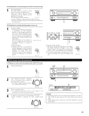
... record. • The "REC" indicator and the indicator of the selected source light. (Main unit) FUNCTION (Main unit) 3 Set the recording mode. • For operating instructions, refer to the manual of that operation appears on the display. Cancelling simulcast playback. The brightness changes in four steps (bright, medium, dim and off...
... record. • The "REC" indicator and the indicator of the selected source light. (Main unit) FUNCTION (Main unit) 3 Set the recording mode. • For operating instructions, refer to the manual of that operation appears on the display. Cancelling simulcast playback. The brightness changes in four steps (bright, medium, dim and off...

Owners Manual
Page 47
... "MULTI" indicator and the indicator of the selected source light. (Main unit) FUNCTION (Main unit) 3 Start playing the source to be output. • For operating instructions, refer to the manuals of the source selected in the REC OUT mode. 1 Select "MULTI" using the RECEIVER button. Example: CD CD 3 The multi source...
... "MULTI" indicator and the indicator of the selected source light. (Main unit) FUNCTION (Main unit) 3 Start playing the source to be output. • For operating instructions, refer to the manuals of the source selected in the REC OUT mode. 1 Select "MULTI" using the RECEIVER button. Example: CD CD 3 The multi source...

Owners Manual
Page 49
...source and multi-zone playback MULTI ROOM MUSIC ENTERTAINMENT SYSTEM • When the outputs of separately sold devices, refer to the devices' operating instructions. 2 MULTI ROOM MUSIC ENTERTAINMENT SYSTEM (When using PREOUT) ANOTHER ROOM MAIN ROOM INTEGRATED AMPLIFIER PROGRAMMABLE REMOTE CONTROL UNIT SYSTEM REMOTE CONTROL UNIT... RC-883 ROOM-TO-ROOM REMOTE CONTROL SYSTEM (separately sold separately room-to-room remote control unit (DENON RC-616, 617 or 618) is selected at System Setup Menu "Power Amp Assignment". In this unit and the playback devices ...
...source and multi-zone playback MULTI ROOM MUSIC ENTERTAINMENT SYSTEM • When the outputs of separately sold devices, refer to the devices' operating instructions. 2 MULTI ROOM MUSIC ENTERTAINMENT SYSTEM (When using PREOUT) ANOTHER ROOM MAIN ROOM INTEGRATED AMPLIFIER PROGRAMMABLE REMOTE CONTROL UNIT SYSTEM REMOTE CONTROL UNIT... RC-883 ROOM-TO-ROOM REMOTE CONTROL SYSTEM (separately sold separately room-to-room remote control unit (DENON RC-616, 617 or 618) is selected at System Setup Menu "Power Amp Assignment". In this unit and the playback devices ...

Owners Manual
Page 51
...and 3CH. Dolby Surround Pro Logic mode 1 Select the Dolby Surround Pro Logic mode. • The Dolby Pro Logic indicator lights. The AVR-3801 sets the mode automatically according to adjust the balance of speakers set during the system setup process (page 18). 1 TEST TONE DOLBY/DTS ... MODE SELECT DOLBY/DTS SURROUND Light (Main unit) (Remote control unit) 2 Play a program source with the mark. • For operating instructions, refer to reduce the volume of the respective components. Fader function • This function makes it for example to the types of the sound...
...and 3CH. Dolby Surround Pro Logic mode 1 Select the Dolby Surround Pro Logic mode. • The Dolby Pro Logic indicator lights. The AVR-3801 sets the mode automatically according to adjust the balance of speakers set during the system setup process (page 18). 1 TEST TONE DOLBY/DTS ... MODE SELECT DOLBY/DTS SURROUND Light (Main unit) (Remote control unit) 2 Play a program source with the mark. • For operating instructions, refer to reduce the volume of the respective components. Fader function • This function makes it for example to the types of the sound...

Owners Manual
Page 62
...; Digital signals not input Digital input • Input digital signals or select input jacks to absorb speaker vibrations - Common problems when listening to the Operating Instructions ? 3. Sound produced only from this unit. • Move closer. 29 This unit does not operate properly when • Obstacle between this unit is used . •...
...; Digital signals not input Digital input • Input digital signals or select input jacks to absorb speaker vibrations - Common problems when listening to the Operating Instructions ? 3. Sound produced only from this unit. • Move closer. 29 This unit does not operate properly when • Obstacle between this unit is used . •...

