
Literature/Product Sheet
Page 1
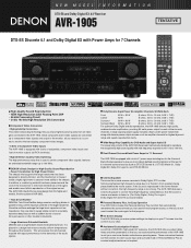
...low-noise design from the higher-end models, like the acclaimed AVR-3805. • Twin Drive Rectifier DENON's Twin Drive Rectifier design uses two rectifying diodes in a design that the sound is too strong. The AVR-1905 features a Cinema Equalizer to correct these high-frequency components so... as sudden bursts of sound from percussion or other musical instruments. • Large Aluminum Extruded Heatsink DENON uses a large heatsink made of DENON's high-grade A/V receivers, the AVR-1905 lets you adjust delay times and other formats emphasizes high-frequency range due to give you need to...
...low-noise design from the higher-end models, like the acclaimed AVR-3805. • Twin Drive Rectifier DENON's Twin Drive Rectifier design uses two rectifying diodes in a design that the sound is too strong. The AVR-1905 features a Cinema Equalizer to correct these high-frequency components so... as sudden bursts of sound from percussion or other musical instruments. • Large Aluminum Extruded Heatsink DENON uses a large heatsink made of DENON's high-grade A/V receivers, the AVR-1905 lets you adjust delay times and other formats emphasizes high-frequency range due to give you need to...
Literature/Product Sheet
Page 2
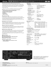
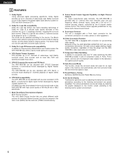
...the Surround Back amplifier channels when the system is registered trademarks of DTS Technology. DENON, LTD. 3-16-11, YUSHIMA, BUNKYO-KU, TOKYO 113-0034, JAPAN 13530704 A s Adjustable Cross-Over Switching The AVR-1905 supports subwoofer cross-over frequencies: 40/60/80/100/120/150/200/250 Hz.... s Support for selected DENON models, along with remote control codes from all speakers in addition to enhance music lovers'...
...the Surround Back amplifier channels when the system is registered trademarks of DTS Technology. DENON, LTD. 3-16-11, YUSHIMA, BUNKYO-KU, TOKYO 113-0034, JAPAN 13530704 A s Adjustable Cross-Over Switching The AVR-1905 supports subwoofer cross-over frequencies: 40/60/80/100/120/150/200/250 Hz.... s Support for selected DENON models, along with remote control codes from all speakers in addition to enhance music lovers'...

Owners Manual
Page 2
... SHOCK, DO NOT EXPOSE THIS APPLIANCE TO RAIN OR MOISTURE. NOTE This product has been tested and found to persons. Modification not expressly approved by DENON may be determined by turning the product OFF and ON, the user is encouraged to try to correct the interference by the FCC, to provide...
... SHOCK, DO NOT EXPOSE THIS APPLIANCE TO RAIN OR MOISTURE. NOTE This product has been tested and found to persons. Modification not expressly approved by DENON may be determined by turning the product OFF and ON, the user is encouraged to try to correct the interference by the FCC, to provide...
Owners Manual
Page 3
Read Instructions - Cleaning - Do not use attachments not recommended by items placed upon or against voltage surges and built-up static charges. Do not place this product during a lightning storm, or when it from the product. 15. Use only with them , paying particular attention to determine that the product is left unattended and unused for long periods of the product and to provide some protection against them might be blocked or covered. Power Sources - This product should be operated only from the wall outlet before the product is a safety feature. This ...
Read Instructions - Cleaning - Do not use attachments not recommended by items placed upon or against voltage surges and built-up static charges. Do not place this product during a lightning storm, or when it from the product. 15. Use only with them , paying particular attention to determine that the product is left unattended and unused for long periods of the product and to provide some protection against them might be blocked or covered. Power Sources - This product should be operated only from the wall outlet before the product is a safety feature. This ...
Owners Manual
Page 4
... provided with home theater sources such as DVD, as well as providing outstanding high fidelity reproduction of features, we recommend that you for choosing the DENON AVR-1905/785 Digital A / V Surround Receiver.
... provided with home theater sources such as DVD, as well as providing outstanding high fidelity reproduction of features, we recommend that you for choosing the DENON AVR-1905/785 Digital A / V Surround Receiver.
Owners Manual
Page 5
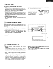
.... Always set -up during this time, the output will be very high after the power switch is turned on AC line voltage. AUX terminal The AVR-1905/785's front panel is turned up is changed. For heat dispersal, leave at least 4 inch/10 cm of space between all other audio components when...
.... Always set -up during this time, the output will be very high after the power switch is turned on AC line voltage. AUX terminal The AVR-1905/785's front panel is turned up is changed. For heat dispersal, leave at least 4 inch/10 cm of space between all other audio components when...
Owners Manual
Page 6
... quality connection, regardless of how the player and the AVR1905/785's video input jacks are greatly simplified. DTS 96/24 compatibility The AVR-1905/785 can be selected according to the listening room's system environment. 6 Front input Terminal The unit is equipped with high sound quality... of Dolby Pro Logic II to decode audio signals recorded on the AVR-1905/785 with a Front Input connector for an input signal in up to 7.1 playback channels, including the surround back channel. The various...
... quality connection, regardless of how the player and the AVR1905/785's video input jacks are greatly simplified. DTS 96/24 compatibility The AVR-1905/785 can be selected according to the listening room's system environment. 6 Front input Terminal The unit is equipped with high sound quality... of Dolby Pro Logic II to decode audio signals recorded on the AVR-1905/785 with a Front Input connector for an input signal in up to 7.1 playback channels, including the surround back channel. The various...

Owners Manual
Page 7
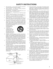
ENGLISH 5 CONNECTIONS • Do not plug in such a way that binding pin plug cords together with digital output jacks R LR L R LRL OUTPUT INPUT CD recorder or Tape deck B Connecting a tape deck Connections for playback: Connect the tape deck's playback output jacks (LINE OUT or PB) to this unit's tape playback (CDR/TAPE IN) jacks using pin plug cords. Route the connection cords, etc., in the AC cord until all connections have been completed. • Be sure to connect the left and right channels properly (left with left, right with the POWER operation switch on the main unit, ...
ENGLISH 5 CONNECTIONS • Do not plug in such a way that binding pin plug cords together with digital output jacks R LR L R LRL OUTPUT INPUT CD recorder or Tape deck B Connecting a tape deck Connections for playback: Connect the tape deck's playback output jacks (LINE OUT or PB) to this unit's tape playback (CDR/TAPE IN) jacks using pin plug cords. Route the connection cords, etc., in the AC cord until all connections have been completed. • Be sure to connect the left and right channels properly (left with left, right with the POWER operation switch on the main unit, ...

Owners Manual
Page 8
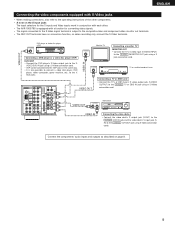
... to the digital input jacks. Note on connecting the digital input jacks • Only audio signals are two sets of the other components. • The AVR-1905/785 is equipped with a function for simultaneous recording or video copying. For details. (See page 7) Connecting a video decks • There are inputs to the S-Video...
... to the digital input jacks. Note on connecting the digital input jacks • Only audio signals are two sets of the other components. • The AVR-1905/785 is equipped with a function for simultaneous recording or video copying. For details. (See page 7) Connecting a video decks • There are inputs to the S-Video...
Owners Manual
Page 9
... TV or DBS IN jack using a S-Video connection cord. • VDP can be connected to the VDP jacks in conjunction with each other. • The AVR-1905/785 is equipped with a function for converting video signals. • The signal connected to the S-Video signal terminal is also possible to connect a video disc...
... TV or DBS IN jack using a S-Video connection cord. • VDP can be connected to the VDP jacks in conjunction with each other. • The AVR-1905/785 is equipped with a function for converting video signals. • The signal connected to the S-Video signal terminal is also possible to connect a video disc...
Owners Manual
Page 10
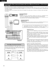
...into a higher quality. If this unit's internal signals. (Color Diffrence Video jack) (Color Diffrence Video jack) MONITOR OUT jacks The AVR-1905/785 is not possible, so when not using the component video monitor output terminal connect the player using regular video jacks (yellow). ..., monitors or video components ("CR, CB and Y", "R-Y, B-Y and Y", "Pr, Pb and Y", etc.). The Video Conversion Function With the AVR-1905/785, the Video signal and the S-video signal which were inputted are converted mutually. Generally speaking, connections using the component video jacks offer te ...
...into a higher quality. If this unit's internal signals. (Color Diffrence Video jack) (Color Diffrence Video jack) MONITOR OUT jacks The AVR-1905/785 is not possible, so when not using the component video monitor output terminal connect the player using regular video jacks (yellow). ..., monitors or video components ("CR, CB and Y", "R-Y, B-Y and Y", "Pr, Pb and Y", etc.). The Video Conversion Function With the AVR-1905/785, the Video signal and the S-video signal which were inputted are converted mutually. Generally speaking, connections using the component video jacks offer te ...

Owners Manual
Page 11
With the antenna attached to the AM antenna terminals. 1 2 3 Remove the vinyl tie and take out the 4 connection line. Connection of the panel. 11 Note to CATV system installer: This reminder is used, do not disconnect the AM loop antenna. • Make sure AM loop antenna lead terminals do not touch metal parts of AM antennas 1. Installation hole Mount on top any stable surface. Return the lever. Mount b. Insert the conductor. 3. GROUND An F-type FM antenna cable plug can be connected to the grounding system of the building, as close to Article 820-40 of cable ...
With the antenna attached to the AM antenna terminals. 1 2 3 Remove the vinyl tie and take out the 4 connection line. Connection of the panel. 11 Note to CATV system installer: This reminder is used, do not disconnect the AM loop antenna. • Make sure AM loop antenna lead terminals do not touch metal parts of AM antennas 1. Installation hole Mount on top any stable surface. Return the lever. Mount b. Insert the conductor. 3. GROUND An F-type FM antenna cable plug can be connected to the grounding system of the building, as close to Article 820-40 of cable ...
Owners Manual
Page 12
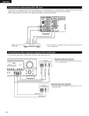
LR LINE OUT DIGITAL OUT VIDEO OUT Video camera OUTPUT R L VIDEO OUT RL LINE OUT VIDEO OUT Connecting a video camera component • Connect the video camera component's output jacks to this unit's V. Video game OUTPUT R L OPTICAL VIDEO OUT RL Connecting a Video game component • Connect the Video game component's output jacks to this unit's V. AUX INPUT jacks. R L R L Front Surround Subwoofer Center Decoder with V.AUX jacks • To connect the video signal, connect using the external input (EXT. Connecting the video component equipped with 6-channel ...
LR LINE OUT DIGITAL OUT VIDEO OUT Video camera OUTPUT R L VIDEO OUT RL LINE OUT VIDEO OUT Connecting a video camera component • Connect the video camera component's output jacks to this unit's V. Video game OUTPUT R L OPTICAL VIDEO OUT RL Connecting a Video game component • Connect the Video game component's output jacks to this unit's V. AUX INPUT jacks. R L R L Front Surround Subwoofer Center Decoder with V.AUX jacks • To connect the video signal, connect using the external input (EXT. Connecting the video component equipped with 6-channel ...
Owners Manual
Page 13
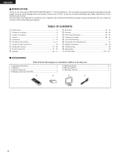
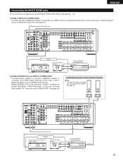
ZONE2 Integrated pre-main amplifier or power amplifier B RC-617 INFRARED SENSOR OUTPUT + RC-616 INFRARED RETRANSMITTER INPUT + AUX OUT 13 ENGLISH Connecting the MULTI ZONE jacks For instructions on operations using the MULTI ZONE FUNCTIONS. (See page 42 ~ 44) [1] ZONE 2 FIXED OUT CONNECTIONS • If another power amplifier or pre-main (integrated) amplifier is selected at System Setup Menu "Power Amp Assign". In this speaker for ZONE2. See page 29. (L) (R) L R Extension jacks for future use. RL ZONE2 Integrated pre-main amplifier B RC-617 INFRARED SENSOR OUTPUT +...
ZONE2 Integrated pre-main amplifier or power amplifier B RC-617 INFRARED SENSOR OUTPUT + RC-616 INFRARED RETRANSMITTER INPUT + AUX OUT 13 ENGLISH Connecting the MULTI ZONE jacks For instructions on operations using the MULTI ZONE FUNCTIONS. (See page 42 ~ 44) [1] ZONE 2 FIXED OUT CONNECTIONS • If another power amplifier or pre-main (integrated) amplifier is selected at System Setup Menu "Power Amp Assign". In this speaker for ZONE2. See page 29. (L) (R) L R Extension jacks for future use. RL ZONE2 Integrated pre-main amplifier B RC-617 INFRARED SENSOR OUTPUT +...
Owners Manual
Page 14
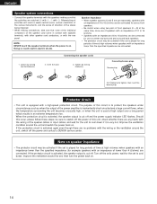
...;/ohms. • Speakers with an impedance of time at high output over a long period which results in electric shocks. Turn off the power and contact a DENON service center. Protector circuit • This unit is very hot. If the protection circuit is activated again even though there are connected. 1. Loosen by turning...
...;/ohms. • Speakers with an impedance of time at high output over a long period which results in electric shocks. Turn off the power and contact a DENON service center. Protector circuit • This unit is very hot. If the protection circuit is activated again even though there are connected. 1. Loosen by turning...
Owners Manual
Page 15
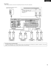
Connections • When making connections, also refer to SURR. Connection jack for ZONE2. See page 29. (L) (R) ENGLISH (L) (R) FRONT SPEAKER SYSTEMS (B) (L) (R) FRONT SPEAKER SYSTEMS (A) CENTER SPEAKER SYSTEM (L) (R) SURROUND SPEAKER SYSTEMS • Precautions when connecting speakers If a speaker is placed near a TV or video monitor, the colors on the screen may be changed to use Surround back with built-in amplifier (super woofer), etc. If this should happen, move the speaker away to a position where it does not have this speaker for subwoofer with one ...
Connections • When making connections, also refer to SURR. Connection jack for ZONE2. See page 29. (L) (R) ENGLISH (L) (R) FRONT SPEAKER SYSTEMS (B) (L) (R) FRONT SPEAKER SYSTEMS (A) CENTER SPEAKER SYSTEM (L) (R) SURROUND SPEAKER SYSTEMS • Precautions when connecting speakers If a speaker is placed near a TV or video monitor, the colors on the screen may be changed to use Surround back with built-in amplifier (super woofer), etc. If this should happen, move the speaker away to a position where it does not have this speaker for subwoofer with one ...
Owners Manual
Page 16
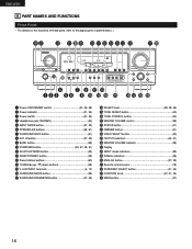
AUX INPUT terminals 5, 12) !6 SURROUND MODE button 38) !7 SURROUND PARAMETER button 47, 55) !8 SELECT knob 38, 48, 56) !9 TONE DEFEAT button 40) @0 TONE CONTROL button 40) @1 MASTER VOLUME control 38) @2 STATUS button 41) @3 DIMMER button 41) @4 VIDEO SELECT button 40) @5 OUTPUT indicators 44, 51) @6 MASTER VOLUME indicator 38) @7 Display @8 INPUT mode indicators 38) @9 SIGNAL indicators 38) #0 ANALOG button 37, 39) #1 Remote control sensor 18) #2 ZONE2/REC SELECT button 41, 44) #3 FUNCTION knob 37, 41, 44) #4 MAIN button 37) 16 IN button 37, 39) o BAND button 59) !0 ...
AUX INPUT terminals 5, 12) !6 SURROUND MODE button 38) !7 SURROUND PARAMETER button 47, 55) !8 SELECT knob 38, 48, 56) !9 TONE DEFEAT button 40) @0 TONE CONTROL button 40) @1 MASTER VOLUME control 38) @2 STATUS button 41) @3 DIMMER button 41) @4 VIDEO SELECT button 40) @5 OUTPUT indicators 44, 51) @6 MASTER VOLUME indicator 38) @7 Display @8 INPUT mode indicators 38) @9 SIGNAL indicators 38) #0 ANALOG button 37, 39) #1 Remote control sensor 18) #2 ZONE2/REC SELECT button 41, 44) #3 FUNCTION knob 37, 41, 44) #4 MAIN button 37) 16 IN button 37, 39) o BAND button 59) !0 ...
Owners Manual
Page 17
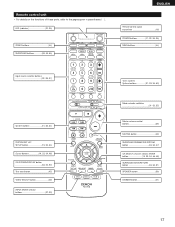
LED (indicator 32, 35) ZONE2 buttons 44) SURROUND buttons 38, 45, 55) ENGLISH Remote control signal transmitter 18) POWER buttons 21, 32~34, 36) MAIN buttons 44) Input source selector buttons 32~35, 37) System buttons 31, 33, 34) SYSTEM SET UP/ SETUP button 19, 33, 34) Cursor buttons 19, 33, 34, 48) ON SCREEN/DISPLAY button 33, 34, 53) Test tone button 45) VIDEO SELECT button 40) INPUT MODE selector buttons 37, 39) Tuner system/ System buttons 31, 33, 34, 59) Mode selector switches 31~33, 35) Master volume control buttons 38) MUTING button 40) SURROUND PARAMETER/SYSTEM ...
LED (indicator 32, 35) ZONE2 buttons 44) SURROUND buttons 38, 45, 55) ENGLISH Remote control signal transmitter 18) POWER buttons 21, 32~34, 36) MAIN buttons 44) Input source selector buttons 32~35, 37) System buttons 31, 33, 34) SYSTEM SET UP/ SETUP button 19, 33, 34) Cursor buttons 19, 33, 34, 48) ON SCREEN/DISPLAY button 33, 34, 53) Test tone button 45) VIDEO SELECT button 40) INPUT MODE selector buttons 37, 39) Tuner system/ System buttons 31, 33, 34, 59) Mode selector switches 31~33, 35) Master volume control buttons 38) MUTING button 40) SURROUND PARAMETER/SYSTEM ...
Owners Manual
Page 18
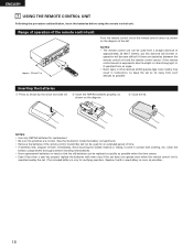
ENGLISH 7 USING THE REMOTE CONTROL UNIT Following the procedure outlined below, insert the batteries before installing new batteries. • Have replacement batteries on hand so that the old batteries can be used from a straight distance of approximately 23 feet/7 meters, but this distance will shorten or operation will become difficult if there are correct. (See the illustration inside the battery compartment.) • Remove the batteries if the remote control transmitter will not be replaced as quickly as possible when the time comes. • Even if less than a year has passed, ...
ENGLISH 7 USING THE REMOTE CONTROL UNIT Following the procedure outlined below, insert the batteries before installing new batteries. • Have replacement batteries on hand so that the old batteries can be used from a straight distance of approximately 23 feet/7 meters, but this distance will shorten or operation will become difficult if there are correct. (See the illustration inside the battery compartment.) • Remove the batteries if the remote control transmitter will not be replaced as quickly as possible when the time comes. • Even if less than a year has passed, ...
Owners Manual
Page 19
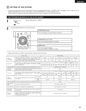
... what appears on -screen display function. Also use for Zone 2. Set the frequency (Hz) below on the monitor screen using the AVR-1905/785's on the display. Front Sp. Surround Back Sp. Input source Digital Inputs Video Input Mode Set the input signal to be output...and their corresponding sizes (SMALL for regular speakers, LARGE for fullsize, full-range) to automatically set up the listening room's AV system centered around the AVR-1905/785. This selects the subwoofer speaker for the different input sources. Large Front L Front R 12 ft 12 ft Front L Front R 0 dB ...
... what appears on -screen display function. Also use for Zone 2. Set the frequency (Hz) below on the monitor screen using the AVR-1905/785's on the display. Front Sp. Surround Back Sp. Input source Digital Inputs Video Input Mode Set the input signal to be output...and their corresponding sizes (SMALL for regular speakers, LARGE for fullsize, full-range) to automatically set up the listening room's AV system centered around the AVR-1905/785. This selects the subwoofer speaker for the different input sources. Large Front L Front R 12 ft 12 ft Front L Front R 0 dB ...
