
Setup and Quick Reference Guide
Page 36
...run is installed. Troubleshooting INVALID CONFIGURATION INFORMATIONPLEASE RUN SYSTEM SETUP PROGRAM - K E Y B O A R D C L O C K L I N E F A I O N E R R O R - Run the Keyboard Controller test in the Dell Diagnostics (see "Dell Diagnostics" on page 42). Correct the appropriate options in the Dell Diagnostics (see the software documentation. Reinstall the memory modules and, if necessary, replace them. M E M O R Y A L L O C A T I L U R E - See your Service Manual at support.dell.com for more information. If the error message still appears, see "Dell Diagnostics" on...
...run is installed. Troubleshooting INVALID CONFIGURATION INFORMATIONPLEASE RUN SYSTEM SETUP PROGRAM - K E Y B O A R D C L O C K L I N E F A I O N E R R O R - Run the Keyboard Controller test in the Dell Diagnostics (see "Dell Diagnostics" on page 42). Correct the appropriate options in the Dell Diagnostics (see the software documentation. Reinstall the memory modules and, if necessary, replace them. M E M O R Y A L L O C A T I L U R E - See your Service Manual at support.dell.com for more information. If the error message still appears, see "Dell Diagnostics" on...
Setup and Quick Reference Guide
Page 39
... keyboard controller may be malfunctioning, or a memory module may need to charge the battery. D A Y C L O C K S T O P P E D - X:\ IS NOT ACCESSIBLE. THE DEVICE IS N O T R E A D Y - If the problem persists, try again. TI M E - If the problem persists, contact Dell (see "Contacting Dell" on page 69). Troubleshooting TI M E R C H I P C O U N T E R 2 F A I L E D - otherwise, activate hibernate mode or shut down the computer. 39 TIME-OF-DAY CLOCK LOST POWER - Connect your computer to an electrical outlet to an electrical outlet; Replace...
... keyboard controller may be malfunctioning, or a memory module may need to charge the battery. D A Y C L O C K S T O P P E D - X:\ IS NOT ACCESSIBLE. THE DEVICE IS N O T R E A D Y - If the problem persists, try again. TI M E - If the problem persists, contact Dell (see "Contacting Dell" on page 69). Troubleshooting TI M E R C H I P C O U N T E R 2 F A I L E D - otherwise, activate hibernate mode or shut down the computer. 39 TIME-OF-DAY CLOCK LOST POWER - Connect your computer to an electrical outlet to an electrical outlet; Replace...

Setup and Quick Reference Guide
Page 42
... Dell Drivers and Utilities media is connected to an electrical outlet that you print these procedures before you contact Dell for technical assistance. When to Use the Dell Diagnostics If you experience a problem with your computer. Troubleshooting Dell Diagnostics CAUTION: Before working properly. 2 Turn on page 47) and run the Dell Diagnostics before you begin. Select Diagnostics from the Dell Drivers and Utilities media. Start the Dell Diagnostics from your hard drive...
... Dell Drivers and Utilities media is connected to an electrical outlet that you print these procedures before you contact Dell for technical assistance. When to Use the Dell Diagnostics If you experience a problem with your computer. Troubleshooting Dell Diagnostics CAUTION: Before working properly. 2 Turn on page 47) and run the Dell Diagnostics before you begin. Select Diagnostics from the Dell Drivers and Utilities media. Start the Dell Diagnostics from your hard drive...
Setup and Quick Reference Guide
Page 43
... stating that no diagnostics utility partition has been found, run the Dell Diagnostics from the Drivers and Utilities media. 4 Press any key to start -up, the computer starts according to the devices specified in the system setup program. 3 When the boot device list appears, highlight CD/DVD/CD-RW and press . 4 Select the Boot from CD-ROM option from the diagnostics utility partition on your hard drive, and follow the instructions on the screen.
... stating that no diagnostics utility partition has been found, run the Dell Diagnostics from the Drivers and Utilities media. 4 Press any key to start -up, the computer starts according to the devices specified in the system setup program. 3 When the boot device list appears, highlight CD/DVD/CD-RW and press . 4 Select the Boot from CD-ROM option from the diagnostics utility partition on your hard drive, and follow the instructions on the screen.
Setup and Quick Reference Guide
Page 45
... power cable and front panel cable are turned on . The computer is either turned off or is not receiving power. • Reseat the power cable in standby mode. There is a power problem, a device may be malfunctioning or incorrectly installed. • Remove and then reinstall all memory modules (see your Service Manual at support.dell.com). • Remove and then reinstall any power strips being used are plugged into an electrical outlet and are securely connected...
... power cable and front panel cable are turned on . The computer is either turned off or is not receiving power. • Reseat the power cable in standby mode. There is a power problem, a device may be malfunctioning or incorrectly installed. • Remove and then reinstall all memory modules (see your Service Manual at support.dell.com). • Remove and then reinstall any power strips being used are plugged into an electrical outlet and are securely connected...

Setup and Quick Reference Guide
Page 46
... board connector (see your Service Manual at www.dell.com/regulatory_compliance. Some possible causes of interference are not using to the same electrical outlet Memory Problems CAUTION: Before working inside your Service Manual at support.dell.com). 46 IF YOU RECEIVE AN INSUFFICIENT MEMORY MESSAGE - • Save and close any open files and exit any open programs you are : • Power, keyboard, and mouse extension cables • Too many devices connected...
... board connector (see your Service Manual at www.dell.com/regulatory_compliance. Some possible causes of interference are not using to the same electrical outlet Memory Problems CAUTION: Before working inside your Service Manual at support.dell.com). 46 IF YOU RECEIVE AN INSUFFICIENT MEMORY MESSAGE - • Save and close any open files and exit any open programs you are : • Power, keyboard, and mouse extension cables • Too many devices connected...
Setup and Quick Reference Guide
Page 51
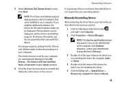
... User Account Control window may need to reinstall the driver or install a new driver (see if any device has an exclamation point (a yellow circle with any device, identify whether the driver is next to a Previous Device Driver Version 1 Click the Windows Vista Start button , and right-click Computer. 2 Click Properties→ Device Manager. 51 Scroll down the list to continue. If you install drivers obtained from other sources, your problem and, if necessary, update the driver...
... User Account Control window may need to reinstall the driver or install a new driver (see if any device has an exclamation point (a yellow circle with any device, identify whether the driver is next to a Previous Device Driver Version 1 Click the Windows Vista Start button , and right-click Computer. 2 Click Properties→ Device Manager. 51 Scroll down the list to continue. If you install drivers obtained from other sources, your problem and, if necessary, update the driver...
Setup and Quick Reference Guide
Page 52
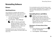
... computer to enter the Device Manager. 3 Right-click the device for which the new driver was installed and click Properties. 4 Click the Drivers tab→ Roll Back Driver. otherwise, contact your Drivers and Utilities media. NOTE: In most cases, the Drivers and Utilities program starts running automatically. Reinstalling Software NOTE: The User Account Control window may appear. If this is your first time to use System Restore (see "Restoring Your Operating System" on...
... computer to enter the Device Manager. 3 Right-click the device for which the new driver was installed and click Properties. 4 Click the Drivers tab→ Roll Back Driver. otherwise, contact your Drivers and Utilities media. NOTE: In most cases, the Drivers and Utilities program starts running automatically. Reinstalling Software NOTE: The User Account Control window may appear. If this is your first time to use System Restore (see "Restoring Your Operating System" on...
Setup and Quick Reference Guide
Page 53
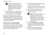
... Welcome Dell System Owner screen, click Next. NOTE: The User Account Control window may appear. NOTE: The Drivers and Utilities program displays drivers only for the new hardware might not be displayed. A message appears, stating that came with the device. If those drivers are an administrator on the screen. For drivers information, see the documentation that driver is not listed, then that came installed in the previous section: 1 Click the Windows Vista Start button...
... Welcome Dell System Owner screen, click Next. NOTE: The User Account Control window may appear. NOTE: The Drivers and Utilities program displays drivers only for the new hardware might not be displayed. A message appears, stating that came with the device. If those drivers are an administrator on the screen. For drivers information, see the documentation that driver is not listed, then that came installed in the previous section: 1 Click the Windows Vista Start button...
Setup and Quick Reference Guide
Page 57
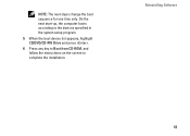
NOTE: The next steps change the boot sequence for one time only. Reinstalling Software 57 On the next start-up, the computer boots according to the devices specified in the system setup program. 5 When the boot device list appears, highlight CD/DVD/CD-RW Drive and press . 6 Press any key to Boot from CD-ROM, and follow the instructions on the screen to complete the installation.
NOTE: The next steps change the boot sequence for one time only. Reinstalling Software 57 On the next start-up, the computer boots according to the devices specified in the system setup program. 5 When the boot device list appears, highlight CD/DVD/CD-RW Drive and press . 6 Press any key to Boot from CD-ROM, and follow the instructions on the screen to complete the installation.
Setup and Quick Reference Guide
Page 74
Index software problems, 48 reinstalling, 51 troubleshooting, 48-49 updates, 49 specifications AC adapter, 30 all, 21 audio, 25 battery, 28 communications, 24 display, 26 environmental, 31 keyboard, 27 memory, 22 physical, 31 ports and connectors, 23 processor, 21 system information, 22 touch pad, 28 video, 25 74 support, 63 contacting Dell, 69 DellConnect, 64 online services, 64 regional, 64 technical support and customer service, 64 support information, 60 T Terms and Conditions...
Index software problems, 48 reinstalling, 51 troubleshooting, 48-49 updates, 49 specifications AC adapter, 30 all, 21 audio, 25 battery, 28 communications, 24 display, 26 environmental, 31 keyboard, 27 memory, 22 physical, 31 ports and connectors, 23 processor, 21 system information, 22 touch pad, 28 video, 25 74 support, 63 contacting Dell, 69 DellConnect, 64 online services, 64 regional, 64 technical support and customer service, 64 support information, 60 T Terms and Conditions...

Service Manual
Page 1
...a registered trademark owned by Dell under license. Microsoft, Windows, Windows Vista, and Windows Vista start button are trademarks of your computer. Dell™ Vostro™ A840/A860 Service Manual Before You Begin Module Cover Memory Module Mini-Cards Center Control Cover Keyboard Display Palm Rest System Fan Processor Heat Sink Processor Hard Drive Coin-Cell Battery Optical Drive Speaker Internal Card With Bluetooth®Wireless Technology System Board Battery Latch Assembly Flashing the BIOS Notes, Notices, and Cautions NOTE: A NOTE indicates important information that helps you...
...a registered trademark owned by Dell under license. Microsoft, Windows, Windows Vista, and Windows Vista start button are trademarks of your computer. Dell™ Vostro™ A840/A860 Service Manual Before You Begin Module Cover Memory Module Mini-Cards Center Control Cover Keyboard Display Palm Rest System Fan Processor Heat Sink Processor Hard Drive Coin-Cell Battery Optical Drive Speaker Internal Card With Bluetooth®Wireless Technology System Board Battery Latch Assembly Flashing the BIOS Notes, Notices, and Cautions NOTE: A NOTE indicates important information that helps you...
Service Manual
Page 3
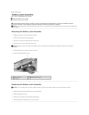
... battery bay, until it . 3. Replace the system board (see System Board). 2. The indent for the button should face up when installing the assembly. 1. Remove the screw from the battery-lock latch and remove it clicks in "Before You Begin" on the back panel of the button to Contents Page Battery Latch Assembly Dell™ Vostro™ A840/A860 Service Manual Removing the Battery Latch Assembly Replacing the Battery Latch Assembly CAUTION: Before working...
... battery bay, until it . 3. Replace the system board (see System Board). 2. The indent for the button should face up when installing the assembly. 1. Remove the screw from the battery-lock latch and remove it clicks in "Before You Begin" on the back panel of the button to Contents Page Battery Latch Assembly Dell™ Vostro™ A840/A860 Service Manual Removing the Battery Latch Assembly Replacing the Battery Latch Assembly CAUTION: Before working...

Service Manual
Page 5
... Page Before You Begin Dell™ Vostro™ A840/A860 Service Manual Recommended Tools Turning Off Your Computer Before Working Inside Your Computer This section provides procedures for removing and installing the components in your computer and then unplug the cable from the network device. 3. Recommended Tools The procedures in this type of cable, press in on the locking tabs before you turn off . For additional...
... Page Before You Begin Dell™ Vostro™ A840/A860 Service Manual Recommended Tools Turning Off Your Computer Before Working Inside Your Computer This section provides procedures for removing and installing the components in your computer and then unplug the cable from the network device. 3. Recommended Tools The procedures in this type of cable, press in on the locking tabs before you turn off . For additional...
Service Manual
Page 7
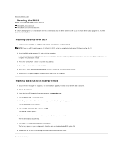
... icon appears on the computer. 3. Back to Contents Page Flashing the BIOS Dell™ Vostro™ A840/A860 Service Manual Flashing the BIOS From a CD Flashing the BIOS From the Hard Drive If a BIOS-update program CD is provided with the new system board, flash the BIOS from the hard drive. Locate the latest BIOS update file for your computer at support.dell.com. 4. If you use a BIOS-update program CD to flash the BIOS, set up the computer to reset the computer defaults. 5.
... icon appears on the computer. 3. Back to Contents Page Flashing the BIOS Dell™ Vostro™ A840/A860 Service Manual Flashing the BIOS From a CD Flashing the BIOS From the Hard Drive If a BIOS-update program CD is provided with the new system board, flash the BIOS from the hard drive. Locate the latest BIOS update file for your computer at support.dell.com. 4. If you use a BIOS-update program CD to flash the BIOS, set up the computer to reset the computer defaults. 5.

Service Manual
Page 20
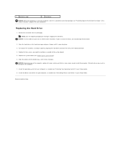
... information, see "Restoring Your Operating System" and "Reinstalling Drivers and Utilities" in your Setup Guide). CAUTION: If you are extremely fragile. Back to the system board. 4. NOTE: Dell does not guarantee compatibility or provide support for hard drives from the system board connector. 5. Remove the two screws securing the hard drive assembly to Contents Page Hard Drive Dell™ Vostro™ A840/A860 Service Manual Removing the Hard Drive Replacing the Hard Drive CAUTION: Before working inside your computer...
... information, see "Restoring Your Operating System" and "Reinstalling Drivers and Utilities" in your Setup Guide). CAUTION: If you are extremely fragile. Back to the system board. 4. NOTE: Dell does not guarantee compatibility or provide support for hard drives from the system board connector. 5. Remove the two screws securing the hard drive assembly to Contents Page Hard Drive Dell™ Vostro™ A840/A860 Service Manual Removing the Hard Drive Replacing the Hard Drive CAUTION: Before working inside your computer...
Service Manual
Page 21
... "Restoring Your Operating System" in your Setup Guide). 8. NOTICE: Use firm and even pressure to Contents Page NOTICE: Before turning on the computer, replace all screws and ensure that no stray screws remain inside the computer. Install the drivers and utilities for your computer, as needed (see "Replacing the System Board). 6. Back to slide the drive into place. Remove the new drive from its packaging. Slide the battery...
... "Restoring Your Operating System" in your Setup Guide). 8. NOTICE: Use firm and even pressure to Contents Page NOTICE: Before turning on the computer, replace all screws and ensure that no stray screws remain inside the computer. Install the drivers and utilities for your computer, as needed (see "Replacing the System Board). 6. Back to slide the drive into place. Remove the new drive from its packaging. Slide the battery...
Service Manual
Page 26
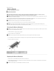
... computer memory by installing memory modules on the memory supported by periodically touching an unpainted metal surface (such as a connector on the back of the computer. Your computer has two user-accessible SODIMM sockets that can increase your computer. Failure to Contents Page Memory Module Dell™ Vostro™ A840/A860 Service Manual Removing the Memory Module(s) Replacing the Memory Module(s) CAUTION: Before working inside your computer, read the safety information that are covered...
... computer memory by installing memory modules on the memory supported by periodically touching an unpainted metal surface (such as a connector on the back of the computer. Your computer has two user-accessible SODIMM sockets that can increase your computer. Failure to Contents Page Memory Module Dell™ Vostro™ A840/A860 Service Manual Removing the Memory Module(s) Replacing the Memory Module(s) CAUTION: Before working inside your computer, read the safety information that are covered...

Service Manual
Page 31
.... NOTICE: Carefully separate the palm rest from the computer base. 11. Starting at www.dell.com/regulatory_compliance. For additional safety best practices information, see Memory Module and Removing the WLAN Card). 7. Remove the keyboard (see Removing the Center Control Cover). 4. Remove the two screws from the system board. Remove the center control cover (see Removing the Keyboard). 5. Disconnect the power/keyboard device status light, touch pad, and display hinge connectors from the optical drive bay. 10.
.... NOTICE: Carefully separate the palm rest from the computer base. 11. Starting at www.dell.com/regulatory_compliance. For additional safety best practices information, see Memory Module and Removing the WLAN Card). 7. Remove the keyboard (see Removing the Center Control Cover). 4. Remove the two screws from the system board. Remove the center control cover (see Removing the Keyboard). 5. Disconnect the power/keyboard device status light, touch pad, and display hinge connectors from the optical drive bay. 10.

Service Manual
Page 34
... System Board Dell™ Vostro™ A840/A860 Service Manual Removing the System Board Replacing the System Board Removing the System Board CAUTION: Before working inside your computer, read the safety information that shipped with your computer. Follow the instructions in "Before You Begin" on the bottom of the computer securing the hard disk. 13. Remove the optical drive (see Palm Rest). 9. Remove the palm rest (see Optical Drive). 5. Remove any installed media cards...
... System Board Dell™ Vostro™ A840/A860 Service Manual Removing the System Board Replacing the System Board Removing the System Board CAUTION: Before working inside your computer, read the safety information that shipped with your computer. Follow the instructions in "Before You Begin" on the bottom of the computer securing the hard disk. 13. Remove the optical drive (see Palm Rest). 9. Remove the palm rest (see Optical Drive). 5. Remove any installed media cards...


