
Owners Manual
Page 3
... Card...9 Removing the Battery...9 Installing the Battery...10 Removing the ExpressCard...10 Installing the ExpressCard...10 Removing the Base Cover...10 Installing the Base Cover...12 Removing the Memory...12 Installing the Memory...12 Removing the Optical Drive...12 Installing the Optical Drive...14 Removing the Hard Drive...14 Installing the Hard Drive...16 Removing the Keyboard...16 Installing the Keyboard...18 Removing the Display Hinge Cover...18 Installing the Display Hinge Cover...19 Removing the Palmrest...19 Installing the Palmrest...24 Removing the ExpressCard Reader...24 Installing...
... Card...9 Removing the Battery...9 Installing the Battery...10 Removing the ExpressCard...10 Installing the ExpressCard...10 Removing the Base Cover...10 Installing the Base Cover...12 Removing the Memory...12 Installing the Memory...12 Removing the Optical Drive...12 Installing the Optical Drive...14 Removing the Hard Drive...14 Installing the Hard Drive...16 Removing the Keyboard...16 Installing the Keyboard...18 Removing the Display Hinge Cover...18 Installing the Display Hinge Cover...19 Removing the Palmrest...19 Installing the Palmrest...24 Removing the ExpressCard Reader...24 Installing...
Owners Manual
Page 4
... Display Bracket...47 Installing the Display Bracket...49 Removing the Camera Module...50 Installing the Camera Module...50 3 System Setup...53 Boot Sequence...53 Navigation Keys...53 System Setup Options...54 Updating the BIOS ...58 System and Setup Password...58 Assigning a System Password and Setup Password 58 Deleting or Changing an Existing System and/or Setup Password 59 4 Diagnostics...61 Enhanced Pre-Boot System Assessment (ePSA) Diagnostics 61 Device Status Lights...61 Battery Status Lights...62 Diagnostic Beep Codes...62 5 Specifications...
... Display Bracket...47 Installing the Display Bracket...49 Removing the Camera Module...50 Installing the Camera Module...50 3 System Setup...53 Boot Sequence...53 Navigation Keys...53 System Setup Options...54 Updating the BIOS ...58 System and Setup Password...58 Assigning a System Password and Setup Password 58 Deleting or Changing an Existing System and/or Setup Password 59 4 Diagnostics...61 Enhanced Pre-Boot System Assessment (ePSA) Diagnostics 61 Device Status Lights...61 Battery Status Lights...62 Diagnostic Beep Codes...62 5 Specifications...
Owners Manual
Page 5
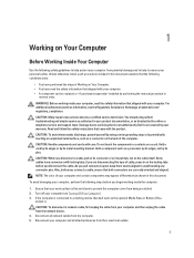
... as the optional Media Base or Battery Slice, undock it. CAUTION: Handle components and cards with the product. NOTE: The color of your computer and certain components may only be replaced or--if purchased separately--installed by a certified service technician. If the computer is connected to a docking device (docked) such as directed by your warranty. WARNING: Before working inside your...
... as the optional Media Base or Battery Slice, undock it. CAUTION: Handle components and cards with the product. NOTE: The color of your computer and certain components may only be replaced or--if purchased separately--installed by a certified service technician. If the computer is connected to a docking device (docked) such as directed by your warranty. WARNING: Before working inside your...
Owners Manual
Page 6
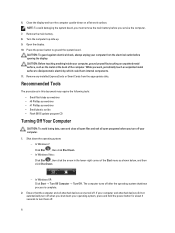
...-down the operating system: - Press the power button to dissipate static electricity, which could harm internal components. 11. In Windows XP: Click Start → Turn Off Computer → Turn Off . Remove any installed ExpressCards or Smart Cards from the electrical outlet before you must remove the main battery before opening the display. Ensure that the computer and all open programs before you turn off when you work surface...
...-down the operating system: - Press the power button to dissipate static electricity, which could harm internal components. 11. In Windows XP: Click Start → Turn Off Computer → Turn Off . Remove any installed ExpressCards or Smart Cards from the electrical outlet before you must remove the main battery before opening the display. Ensure that the computer and all open programs before you turn off when you work surface...
Owners Manual
Page 7
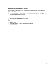
... any replacement procedure, ensure you connect any external devices, cards, and cables before turning on your computer and all attached devices to the computer, use batteries designed for this particular Dell computer. Connect any external devices, such as a port replicator, battery slice, or media base, and replace any cards, such as an ExpressCard. 2. Do not use only the battery designed for other Dell computers. 1. CAUTION: To connect a network cable, first plug the cable into the network device and...
... any replacement procedure, ensure you connect any external devices, cards, and cables before turning on your computer and all attached devices to the computer, use batteries designed for this particular Dell computer. Connect any external devices, such as a port replicator, battery slice, or media base, and replace any cards, such as an ExpressCard. 2. Do not use only the battery designed for other Dell computers. 1. CAUTION: To connect a network cable, first plug the cable into the network device and...
Owners Manual
Page 12
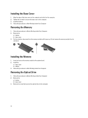
... After Working Inside Your Computer. Lift and remove the memory module from the memory module until it on the computer. 2. Removing the Optical Drive 1. Remove the screw that secures the optical drive to the computer. 3. Insert and secure the memory module to the system board. 2. Install the battery. 4. Remove the: a) battery b) base cover 3. Install the: a) base cover b) battery 3. Removing the Memory 1. Remove the: a) battery b) base cover 3. Follow the procedures in After Working Inside Your Computer. Installing the Base Cover 1.
... After Working Inside Your Computer. Lift and remove the memory module from the memory module until it on the computer. 2. Removing the Optical Drive 1. Remove the screw that secures the optical drive to the computer. 3. Insert and secure the memory module to the system board. 2. Install the battery. 4. Remove the: a) battery b) base cover 3. Install the: a) base cover b) battery 3. Removing the Memory 1. Remove the: a) battery b) base cover 3. Follow the procedures in After Working Inside Your Computer. Installing the Base Cover 1.
Owners Manual
Page 14
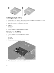
... optical drive into the compartment on the chassis. 3. Removing the Hard Drive 1. Installing the Optical Drive 1. Tighten the screw to secure the optical drive to release the hard drive from the hard drive connector. 14 Follow the procedures in After Working Inside Your Computer. Install the: a) base cover b) battery 5. Replace the optical-drive bracket and tighten the screws that secure the hard drive to the optical-drive bracket. 2. Remove the: a) battery b) base cover 3.
... optical drive into the compartment on the chassis. 3. Removing the Hard Drive 1. Installing the Optical Drive 1. Tighten the screw to secure the optical drive to release the hard drive from the hard drive connector. 14 Follow the procedures in After Working Inside Your Computer. Install the: a) base cover b) battery 5. Replace the optical-drive bracket and tighten the screws that secure the hard drive to the optical-drive bracket. 2. Remove the: a) battery b) base cover 3.
Owners Manual
Page 24
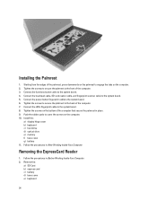
... system board. 4. Install the: a) display hinge cover b) keyboard c) hard drive d) optical drive e) memory f) base cover g) battery 11. Connect the functions button cable to the front of the computer. 3. Connect the LEDs fingerprint cable to cover the screws on the computer. 2. Push the rubber pads to the system board. 8. Remove the: a) SD Card b) express card c) battery d) base cover e) keyboard 24 Connect the touchpad cable, SD card reader cable, and fingerprint scanner cable to engage the tabs on the computer. 10. Follow the procedures in Before Working...
... system board. 4. Install the: a) display hinge cover b) keyboard c) hard drive d) optical drive e) memory f) base cover g) battery 11. Connect the functions button cable to the front of the computer. 3. Connect the LEDs fingerprint cable to cover the screws on the computer. 2. Push the rubber pads to the system board. 8. Remove the: a) SD Card b) express card c) battery d) base cover e) keyboard 24 Connect the touchpad cable, SD card reader cable, and fingerprint scanner cable to engage the tabs on the computer. 10. Follow the procedures in Before Working...

Owners Manual
Page 32
Install the: a) SD card reader b) palmrest c) display hinge cover d) keyboard e) hard drive f) optical drive g) base cover h) battery i) express card j) SD card 9. Follow the procedures in Before Working Inside Your Computer. 2. Connect the speaker cable. 7. Follow the procedures in After Working Inside Your Computer. Removing the Heat Sink 1. Remove the: a) SD card b) express card c) battery d) base cover 32 Connect the system fan cable and the power cable. 8. Tighten the screws to secure the system board to the port connectors and place the...
Install the: a) SD card reader b) palmrest c) display hinge cover d) keyboard e) hard drive f) optical drive g) base cover h) battery i) express card j) SD card 9. Follow the procedures in Before Working Inside Your Computer. 2. Connect the speaker cable. 7. Follow the procedures in After Working Inside Your Computer. Removing the Heat Sink 1. Remove the: a) SD card b) express card c) battery d) base cover 32 Connect the system fan cable and the power cable. 8. Tighten the screws to secure the system board to the port connectors and place the...
Owners Manual
Page 36
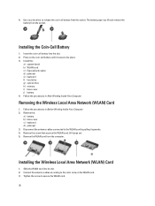
... its slot. 2. Remove the: a) battery b) base cover c) keyboard d) palmrest 3. Connect the antenna cables according to release the coin-cell battery from the socket. Installing the Coin-Cell Battery 1. Removing the Wireless Local Area Network (WLAN) Card 1. Follow the procedures in After Working Inside Your Computer. Use a screw driver to the color code on the coin-cell battery until it secures into place. 3. Install the: a) system board b) WLAN card c) ExpressCard reader d) palmrest e) keyboard f) hard drive g) optical drive h) memory i) base cover j) battery 4. Remove...
... its slot. 2. Remove the: a) battery b) base cover c) keyboard d) palmrest 3. Connect the antenna cables according to release the coin-cell battery from the socket. Installing the Coin-Cell Battery 1. Removing the Wireless Local Area Network (WLAN) Card 1. Follow the procedures in After Working Inside Your Computer. Use a screw driver to the color code on the coin-cell battery until it secures into place. 3. Install the: a) system board b) WLAN card c) ExpressCard reader d) palmrest e) keyboard f) hard drive g) optical drive h) memory i) base cover j) battery 4. Remove...
Owners Manual
Page 50
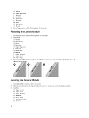
...it to remove the camera from the system. Follow the procedures in After Working Inside Your Computer. Install the: a) display bracket b) display bezel c) display assembly d) LAN board e) system board f) express card reader g) speakers 50 Disconnect the LVDS and camera cable. Connect the LVDS and camera cable to the camera. 2. Follow the procedures in Before Working Inside Your Computer. 2. Removing the Camera Module 1. Remove the: a) SD Card b) express card c) battery d) base cover e) display hinge cover f) keyboard g) optical drive h) palmrest i) display assembly j) display bezel...
...it to remove the camera from the system. Follow the procedures in After Working Inside Your Computer. Install the: a) display bracket b) display bezel c) display assembly d) LAN board e) system board f) express card reader g) speakers 50 Disconnect the LVDS and camera cable. Connect the LVDS and camera cable to the camera. 2. Follow the procedures in Before Working Inside Your Computer. 2. Removing the Camera Module 1. Remove the: a) SD Card b) express card c) battery d) base cover e) display hinge cover f) keyboard g) optical drive h) palmrest i) display assembly j) display bezel...
Owners Manual
Page 53
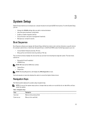
... setup navigation keys. The boot-menu options are recorded but do not take effect until you restart the system. NOTE: For most of the system setup options, changes that you can : • Change the NVRAM settings after you add or remove hardware • View the system hardware configuration • Enable or disable integrated devices • Set performance and power management thresholds • Manage your computer hardware and specify BIOS‐level options. 3 System Setup System Setup enables...
... setup navigation keys. The boot-menu options are recorded but do not take effect until you restart the system. NOTE: For most of the system setup options, changes that you can : • Change the NVRAM settings after you add or remove hardware • View the system hardware configuration • Enable or disable integrated devices • Set performance and power management thresholds • Manage your computer hardware and specify BIOS‐level options. 3 System Setup System Setup enables...
Owners Manual
Page 55
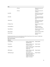
... hard drive. Virtualization Enable or disable the Intel Default: Enabled Virtualization feature. Displays the processor L3 cache size. Displays the model number and capacity of each option and its default value. Displays the memory in-built on the computer. USB Wake Support Allows USB devices to the on-board network card. Displays the type of the optical drive. Integrated NIC Enable or disable the power Default: Enabled supply to wake-up the computer from standby. Displays the model number and capacity of keyboard...
... hard drive. Virtualization Enable or disable the Intel Default: Enabled Virtualization feature. Displays the processor L3 cache size. Displays the model number and capacity of each option and its default value. Displays the memory in-built on the computer. USB Wake Support Allows USB devices to the on-board network card. Displays the type of the optical drive. Integrated NIC Enable or disable the power Default: Enabled supply to wake-up the computer from standby. Displays the model number and capacity of keyboard...
Owners Manual
Page 56
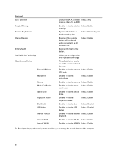
...Start Technology Miscellaneous Devices External USB Ports Microphone Camera Media Card Reader Optical Drive Fingerprint Reader Boot Disable USB debug Internal Bluetooth Internal WLAN Internal WWAN Change the SATA controller Default: AHCI mode to an AC power source. Default: Enabled Enables or disables media Default: Enabled card reader. Default: Enabled Specifies the health of the function key . Default: Disabled Enables or disables USB debug. Enables or disables adapter Default: Enabled warnings. Enables or disables external Default: Enabled USB ports. Enables or disables...
...Start Technology Miscellaneous Devices External USB Ports Microphone Camera Media Card Reader Optical Drive Fingerprint Reader Boot Disable USB debug Internal Bluetooth Internal WLAN Internal WWAN Change the SATA controller Default: AHCI mode to an AC power source. Default: Enabled Enables or disables media Default: Enabled card reader. Default: Enabled Specifies the health of the function key . Default: Disabled Enables or disables USB debug. Enables or disables adapter Default: Enabled warnings. Enables or disables external Default: Enabled USB ports. Enables or disables...
Owners Manual
Page 57
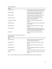
... System Setup. 57 Specifies the removable drive the computer can boot through at start up. Specifies which the computer will boot through . Allows you to enter it. Boot Options Boot Boot Priority Order Removable Drive Hard Disk Drives USB Storage Device CD/DVD/CD-RW Drive Network Specifies the order of different devices in which CD/DVD the computer can be used to change the boot sequence. Allows you to set , this computer or not (Default: Cleared/Not installed) This field displays if a HDD password...
... System Setup. 57 Specifies the removable drive the computer can boot through at start up. Specifies which the computer will boot through . Allows you to enter it. Boot Options Boot Boot Priority Order Removable Drive Hard Disk Drives USB Storage Device CD/DVD/CD-RW Drive Network Specifies the order of different devices in which CD/DVD the computer can be used to change the boot sequence. Allows you to set , this computer or not (Default: Cleared/Not installed) This field displays if a HDD password...
Owners Manual
Page 58
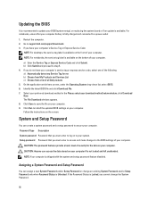
... on replacing the system board or if an update is shipped with the system and setup password feature disabled. On the application and drivers screen, under the Operating System drop-down list, select BIOS. 6. The File Download window appears. 8. Click Run to install the updated BIOS settings on to your computer. CAUTION: The password features provide a basic level of your download method below window; For notebooks, ensure that you cannot change an...
... on replacing the system board or if an update is shipped with the system and setup password feature disabled. On the application and drivers screen, under the Operating System drop-down list, select BIOS. 6. The File Download window appears. 8. Click Run to install the updated BIOS settings on to your computer. CAUTION: The password features provide a basic level of your download method below window; For notebooks, ensure that you cannot change an...
Owners Manual
Page 61
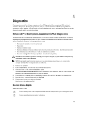
... As the computer boots, press the key as system diagnostics) performs a complete check of your hardware. Device Status Lights Turns on when you solve the problem. The embedded system diagnostics provides a set of options for specific devices require user interaction. Using this program with the BIOS and is launched by the BIOS internally. Note the error code and contact Dell. The ePSA is displayed, listing all the detected devices. 4. Device Status Lights Table 6. The...
... As the computer boots, press the key as system diagnostics) performs a complete check of your hardware. Device Status Lights Turns on when you solve the problem. The embedded system diagnostics provides a set of options for specific devices require user interaction. Using this program with the BIOS and is launched by the BIOS internally. Note the error code and contact Dell. The ePSA is displayed, listing all the detected devices. 4. Device Status Lights Table 6. The...
Owners Manual
Page 62
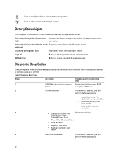
... 7. Battery Status Lights If the computer is connected to indicate battery charge status. Alternately blinking amber light with steady Temporary battery failure with AC adapter present. Diagnostic Beep Codes The following steps • reseat the memory if an additional memory is available • install that may be emitted by the computer when your laptop. white light Constantly blinking amber light Fatal battery failure with AC adapter present. Turns on when wireless networking is enabled. Turns...
... 7. Battery Status Lights If the computer is connected to indicate battery charge status. Alternately blinking amber light with steady Temporary battery failure with AC adapter present. Diagnostic Beep Codes The following steps • reseat the memory if an additional memory is available • install that may be emitted by the computer when your laptop. white light Constantly blinking amber light Fatal battery failure with AC adapter present. Turns on when wireless networking is enabled. Turns...
Owners Manual
Page 65
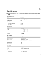
For more information regarding the configuration of your computer, click Start (Start icon) → Help and Support, and then select the option to 6 MB Table 10. Table 8. Audio Feature Type Controller: Vostro 3360 Description 2 channel high definition audio Cirrus Logic CS4213D 65 Memory Feature Memory connector Memory capacity Memory type Minimum memory Maximum memory Description two SODIMM slots 2 GB, 4 GB, 6 GB, or 8 GB DDR3 SDRAM (1333 MHz and 1600...
For more information regarding the configuration of your computer, click Start (Start icon) → Help and Support, and then select the option to 6 MB Table 10. Table 8. Audio Feature Type Controller: Vostro 3360 Description 2 channel high definition audio Cirrus Logic CS4213D 65 Memory Feature Memory connector Memory capacity Memory type Minimum memory Maximum memory Description two SODIMM slots 2 GB, 4 GB, 6 GB, or 8 GB DDR3 SDRAM (1333 MHz and 1600...
Owners Manual
Page 66
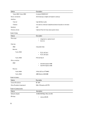
Camera Feature Camera Resolution Video Resolution (maximum) Table 14. Feature Vostro 3460 / Vostro 3560 Stereo conversion Interface: Internal External Speakers Volume controls Table 12. Communication Feature Network adapter Wireless 66 Description Conexant CX20672-21Z 24-bit (analog-to-digital and digital-to-analog) high definition audio microphone-in/stereo headphones/external speakers connector 2 W keyboard function keys and program menus Description • integrated on system board • discrete integrated video • PCI...
Camera Feature Camera Resolution Video Resolution (maximum) Table 14. Feature Vostro 3460 / Vostro 3560 Stereo conversion Interface: Internal External Speakers Volume controls Table 12. Communication Feature Network adapter Wireless 66 Description Conexant CX20672-21Z 24-bit (analog-to-digital and digital-to-analog) high definition audio microphone-in/stereo headphones/external speakers connector 2 W keyboard function keys and program menus Description • integrated on system board • discrete integrated video • PCI...


