
Owner's Manual
Page 5
... designed for an earlier Microsoft® Windows® operating system 68 A solid blue screen appears 68 Other software problems 69 Media Card Reader Problems 70 Memory Problems 71 Mouse Problems 72 Network Problems 73 Power Problems 74 Printer Problems 75 Scanner Problems 76 Sound and Speaker Problems 77 No sound from...
... designed for an earlier Microsoft® Windows® operating system 68 A solid blue screen appears 68 Other software problems 69 Media Card Reader Problems 70 Memory Problems 71 Mouse Problems 72 Network Problems 73 Power Problems 74 Printer Problems 75 Scanner Problems 76 Sound and Speaker Problems 77 No sound from...
Owner's Manual
Page 7
... the Computer Cover 103 Inside View of Your Computer 105 System Board Components 106 Power Supply DC Connector Pin Assignments . . . . . 108 Memory 111 Memory Installation Guidelines 112 Installing Memory 113 Removing Memory 115 Cards 115 PCI and PCI Express Cards 116 Bezel 123 Removing the Bezel 123 Replacing the Bezel 125 Drives 126 Recommended...
... the Computer Cover 103 Inside View of Your Computer 105 System Board Components 106 Power Supply DC Connector Pin Assignments . . . . . 108 Memory 111 Memory Installation Guidelines 112 Installing Memory 113 Removing Memory 115 Cards 115 PCI and PCI Express Cards 116 Bezel 123 Removing the Bezel 123 Replacing the Bezel 125 Drives 126 Recommended...
Owner's Manual
Page 13
...Computer documentation, details on my computer configuration, product specifications, and white papers • Downloads - Finding Information 13 Troubleshooting hints and Dell Support Website - Upgrade information for your computer, you should also reinstall the DSS utility. Certified drivers, patches, and software updates...System Software: you reinstall the operating system for your region to System configuration. components, such as memory, the hard drive, and the operating system • Customer Care - NOTE: Corporate, government, and education customers can also...
...Computer documentation, details on my computer configuration, product specifications, and white papers • Downloads - Finding Information 13 Troubleshooting hints and Dell Support Website - Upgrade information for your computer, you should also reinstall the DSS utility. Certified drivers, patches, and software updates...System Software: you reinstall the operating system for your region to System configuration. components, such as memory, the hard drive, and the operating system • Customer Care - NOTE: Corporate, government, and education customers can also...

Owner's Manual
Page 27
... Continuously play the current title or chapter Go to increase or decrease the volume. Adjusting the Volume NOTE: When the speakers are using too much memory and preventing DVD playback, adjust the display properties: Windows XP 1 Click Start→ Control Panel→ Appearance and Themes. 2 Under Pick a task..., click Change the...
... Continuously play the current title or chapter Go to increase or decrease the volume. Adjusting the Volume NOTE: When the speakers are using too much memory and preventing DVD playback, adjust the display properties: Windows XP 1 Click Start→ Control Panel→ Appearance and Themes. 2 Under Pick a task..., click Change the...
Owner's Manual
Page 31
...: • xD-Picture Card • SmartMedia (SMC) • CompactFlash Type I and II (CF I/II) • MicroDrive Card • SecureDigital Card (SD) • MultiMediaCard (MMC) • Memory Stick (MS/MS Pro) For information on installing a Media Card Reader, see "Installing a Media Card Reader" on the CD-RW and try again. If you...
...: • xD-Picture Card • SmartMedia (SMC) • CompactFlash Type I and II (CF I/II) • MicroDrive Card • SecureDigital Card (SD) • MultiMediaCard (MMC) • Memory Stick (MS/MS Pro) For information on installing a Media Card Reader, see "Installing a Media Card Reader" on the CD-RW and try again. If you...
Owner's Manual
Page 32
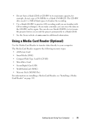
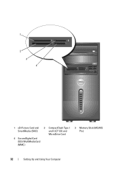
1 2 3 4 1 xD-Picture Card and SmartMedia (SMC) 2 CompactFlash Type I and II (CF I/II) and MicroDrive Card 4 SecureDigital Card (SD)/ MultiMediaCard (MMC) 3 Memory Stick (MS/MS Pro) 32 Setting Up and Using Your Computer
1 2 3 4 1 xD-Picture Card and SmartMedia (SMC) 2 CompactFlash Type I and II (CF I/II) and MicroDrive Card 4 SecureDigital Card (SD)/ MultiMediaCard (MMC) 3 Memory Stick (MS/MS Pro) 32 Setting Up and Using Your Computer
Owner's Manual
Page 36
... Computer Because the keyboard and mouse do not function in prior to entering hibernate mode. To immediately activate standby mode without a period of the computer memory, Dell creates an appropriately sized hibernate mode file before shipping the computer to a reserved area on the keyboard or move the mouse. To exit hibernate mode...
... Computer Because the keyboard and mouse do not function in prior to entering hibernate mode. To immediately activate standby mode without a period of the computer memory, Dell creates an appropriately sized hibernate mode file before shipping the computer to a reserved area on the keyboard or move the mouse. To exit hibernate mode...
Owner's Manual
Page 40
... conserves power by copying system data to a reserved area on the keyboard or moving the mouse does not bring the computer out of the computer memory, Dell creates an appropriately sized hibernate mode file before it was in before shipping the computer to you can define standby mode settings, display mode settings...
... conserves power by copying system data to a reserved area on the keyboard or moving the mouse does not bring the computer out of the computer memory, Dell creates an appropriately sized hibernate mode file before it was in before shipping the computer to you can define standby mode settings, display mode settings...
Owner's Manual
Page 65
... restore computer resources. A R E Q U I N - D L L F I S N O T R E A D Y - Solving Problems 65 Error Messages If the message is missing an essential file. T H E D E V I C E I L E W A S N O T F O U N D - The drive cannot read the disk. S YS T E M D I S K E R R O R - NOT ENOUGH MEMORY OR RESOURCES.
... restore computer resources. A R E Q U I N - D L L F I S N O T R E A D Y - Solving Problems 65 Error Messages If the message is missing an essential file. T H E D E V I C E I L E W A S N O T F O U N D - The drive cannot read the disk. S YS T E M D I S K E R R O R - NOT ENOUGH MEMORY OR RESOURCES.
Owner's Manual
Page 71
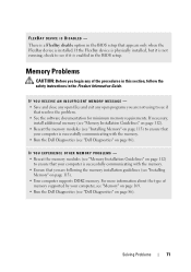
... Problems 71 FLEXBAY DEVICE IS DISABLED - There is successfully communicating with the memory. • Run the Dell Diagnostics (see "Installing Memory" on page 86). If necessary, install additional memory (see "Memory Installation Guidelines" on page 112). • Reseat the memory modules (see "Installing Memory" on page 113) to ensure that your computer is successfully communicating with the...
... Problems 71 FLEXBAY DEVICE IS DISABLED - There is successfully communicating with the memory. • Run the Dell Diagnostics (see "Installing Memory" on page 86). If necessary, install additional memory (see "Memory Installation Guidelines" on page 112). • Reseat the memory modules (see "Installing Memory" on page 113) to ensure that your computer is successfully communicating with the...
Owner's Manual
Page 74
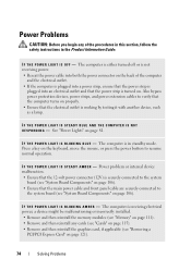
... Press a key on page 81. I F T H E P O W E R L I G H T I S B L I N K I N G B L U E - The computer is receiving electrical power, a device might be malfunctioning or incorrectly installed. • Remove and then reinstall the memory modules (see "Memory" on page 111). • Remove and then reinstall any of the computer and the electrical outlet. • If the computer is plugged into a power...
... Press a key on page 81. I F T H E P O W E R L I G H T I S B L I N K I N G B L U E - The computer is receiving electrical power, a device might be malfunctioning or incorrectly installed. • Remove and then reinstall the memory modules (see "Memory" on page 111). • Remove and then reinstall any of the computer and the electrical outlet. • If the computer is plugged into a power...
Owner's Manual
Page 82
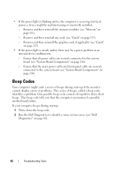
...any cards (see "System Board Components" on page 115). - Ensure that all power cables are securely connected to the system board (see "Memory" on page 106). • If the power light is blinking amber, the computer is steady amber, there may be malfunctioning or incorrectly installed... the power light is receiving electrical power, a device might emit a series of beeps during startup: 1 Write down the beep code. 2 Run the Dell Diagnostics to identify a more serious cause (see "Cards" on page 86). 82 Troubleshooting Tools One possible beep code consists of beeps, called a beep...
...any cards (see "System Board Components" on page 115). - Ensure that all power cables are securely connected to the system board (see "Memory" on page 106). • If the power light is blinking amber, the computer is steady amber, there may be malfunctioning or incorrectly installed... the power light is receiving electrical power, a device might emit a series of beeps during startup: 1 Write down the beep code. 2 Run the Dell Diagnostics to identify a more serious cause (see "Cards" on page 86). 82 Troubleshooting Tools One possible beep code consists of beeps, called a beep...
Owner's Manual
Page 83
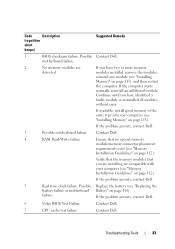
... (see "Replacing the battery failure or motherboard Battery" on page 112). If the problem persists, contact Dell. 6 Video BIOS Test Failure Contact Dell. 7 CPU cache test failure Contact Dell. Troubleshooting Tools 83 Possible Replace the battery (see "Installing Memory" on page 112). failure. Code Description (repetitive short beeps) Suggested Remedy 1 BIOS checksum failure. If...
... (see "Replacing the battery failure or motherboard Battery" on page 112). If the problem persists, contact Dell. 6 Video BIOS Test Failure Contact Dell. 7 CPU cache test failure Contact Dell. Troubleshooting Tools 83 Possible Replace the battery (see "Installing Memory" on page 112). failure. Code Description (repetitive short beeps) Suggested Remedy 1 BIOS checksum failure. If...
Owner's Manual
Page 87
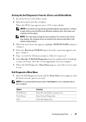
...you wait too long and the operating system logo appears, continue to run a complete test on your computer. Dell Diagnostics Main Menu 1 After the Dell Diagnostics loads and the Main Menu screen appears, click the button for the option you see the Microsoft Windows desktop...Select the Boot from CD-ROM option from the numbered list. Option Test Memory Test System Exit Function Runs the stand-alone memory test Runs System Diagnostics Exits the Diagnostics Troubleshooting Tools 87 Starting the Dell Diagnostics From the Drivers and Utilities Media 1 Insert the Drivers and Utilities...
...you wait too long and the operating system logo appears, continue to run a complete test on your computer. Dell Diagnostics Main Menu 1 After the Dell Diagnostics loads and the Main Menu screen appears, click the button for the option you see the Microsoft Windows desktop...Select the Boot from CD-ROM option from the numbered list. Option Test Memory Test System Exit Function Runs the stand-alone memory test Runs System Diagnostics Exits the Diagnostics Troubleshooting Tools 87 Starting the Dell Diagnostics From the Drivers and Utilities Media 1 Insert the Drivers and Utilities...

Owner's Manual
Page 89
... that are not on your computer or all devices from system setup, memory, and various internal tests, and it displays the information in the device list in the left pane of the screen. To exit the Dell Diagnostics and restart the computer, close the test screen to return to ...the test settings. 5 When the tests are installing software appropriate for the selected device. Drivers What Is a Driver? All devices require a driver program. Dell ships your computer to you to the Main Menu screen. The device list may not display the names of specialized commands that use the device...
... that are not on your computer or all devices from system setup, memory, and various internal tests, and it displays the information in the device list in the left pane of the screen. To exit the Dell Diagnostics and restart the computer, close the test screen to return to ...the test settings. 5 When the tests are installing software appropriate for the selected device. Drivers What Is a Driver? All devices require a driver program. Dell ships your computer to you to the Main Menu screen. The device list may not display the names of specialized commands that use the device...
Owner's Manual
Page 106
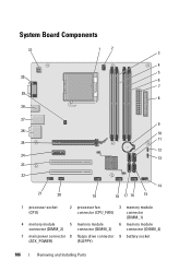
System Board Components 31 30 29 28 1 2 3 4 5 6 7 8 27 9 26 10 11 25 12 24 13 23 22 21 20 14 19 18 17 16 15 1 processor socket (CPU) 2 processor fan connector (CPU_FAN) 3 memory module connector (DIMM_1) 4 memory module 5 memory module 6 memory module connector (DIMM_2) connector (DIMM_3) connector (DIMM_4) 7 main power connector 8 floppy drive connector 9 battery socket (ATX_POWER) (FLOPPY) 106 Removing and Installing Parts
System Board Components 31 30 29 28 1 2 3 4 5 6 7 8 27 9 26 10 11 25 12 24 13 23 22 21 20 14 19 18 17 16 15 1 processor socket (CPU) 2 processor fan connector (CPU_FAN) 3 memory module connector (DIMM_1) 4 memory module 5 memory module 6 memory module connector (DIMM_2) connector (DIMM_3) connector (DIMM_4) 7 main power connector 8 floppy drive connector 9 battery socket (ATX_POWER) (FLOPPY) 106 Removing and Installing Parts
Owner's Manual
Page 111
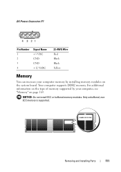
DC Power Connector P7 Pin Number 1 2 3 4 Signal Name +5 VDC GND GND +12 VADC 22-AWG Wire Red Black Black Yellow Memory You can increase your computer memory by your computer, see "Memory" on the system board. Removing and Installing Parts 111 Only unbuffered, nonECC memory is supported. For additional information on the type of memory supported by installing memory modules on page 169. NOTICE: Do not install ECC or buffered memory modules. Your computer supports DDR2 memory.
DC Power Connector P7 Pin Number 1 2 3 4 Signal Name +5 VDC GND GND +12 VADC 22-AWG Wire Red Black Black Yellow Memory You can increase your computer memory by your computer, see "Memory" on the system board. Removing and Installing Parts 111 Only unbuffered, nonECC memory is supported. For additional information on the type of memory supported by installing memory modules on page 169. NOTICE: Do not install ECC or buffered memory modules. Your computer supports DDR2 memory.

Owner's Manual
Page 112
...computer will operate, but with connectors DIMM_1 and DIMM_3, then connectors DIMM_2 and DIMM_4. Memory Installation Guidelines • DIMM connectors must install it in connector DIMM_1. • For best performance, memory modules should be populated in numerical order beginning with a slight reduction in performance. (...See the label on the module to determine the module's capacity.) For example, if you must be installed in pairs of memory modules in connectors DIMM_3 and DIMM_4 112 Removing and Installing Parts If a single DIMM is installed, you install a mixed pair of ...
...computer will operate, but with connectors DIMM_1 and DIMM_3, then connectors DIMM_2 and DIMM_4. Memory Installation Guidelines • DIMM connectors must install it in connector DIMM_1. • For best performance, memory modules should be populated in numerical order beginning with a slight reduction in performance. (...See the label on the module to determine the module's capacity.) For example, if you must be installed in pairs of memory modules in connectors DIMM_3 and DIMM_4 112 Removing and Installing Parts If a single DIMM is installed, you install a mixed pair of ...
Owner's Manual
Page 113
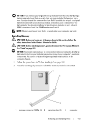
... in pairs either in "Before You Begin" on page 115. NOTE: Memory purchased from your body before you purchased the new modules from Dell. NOTICE: If you remove your original memory modules from the computer during a memory upgrade, keep them separate from any new modules that you may not start properly. If possible, do...
... in pairs either in "Before You Begin" on page 115. NOTE: Memory purchased from your body before you purchased the new modules from Dell. NOTICE: If you remove your original memory modules from the computer during a memory upgrade, keep them separate from any new modules that you may not start properly. If possible, do...
Owner's Manual
Page 114
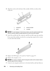
... module snaps into position. 3 Align the notch on the bottom of the module with the crossbar in the connector. 3 2 1 4 1 cutouts (2) 3 notch 2 memory module 4 crossbar NOTICE: To avoid damage to the memory module, press the module straight down into the connector while you insert the module correctly, the securing clips snap into the...
... module snaps into position. 3 Align the notch on the bottom of the module with the crossbar in the connector. 3 2 1 4 1 cutouts (2) 3 notch 2 memory module 4 crossbar NOTICE: To avoid damage to the memory module, press the module straight down into the connector while you insert the module correctly, the securing clips snap into the...


