User Manual
Page 1
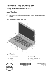
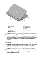
camera status light 2. speakers (2) 5. Vostro 1440/1450 Figure 1. display 4. camera 3. optical drive Regulatory Model P22G,P18F Regulatory Type P22G001,P22G003,P18F001,P18F002 2011 - 05 Front And Back - Front View 1. USB 2.0 connectors (2) 6. Dell Vostro 1440/1540/1450/1550 Setup And Features Information About Warnings WARNING: A WARNING indicates a potential for property damage, personal injury, or death.
camera status light 2. speakers (2) 5. Vostro 1440/1450 Figure 1. display 4. camera 3. optical drive Regulatory Model P22G,P18F Regulatory Type P22G001,P22G003,P18F001,P18F002 2011 - 05 Front And Back - Front View 1. USB 2.0 connectors (2) 6. Dell Vostro 1440/1540/1450/1550 Setup And Features Information About Warnings WARNING: A WARNING indicates a potential for property damage, personal injury, or death.
User Manual
Page 2
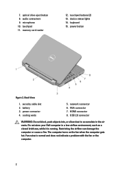
... drive eject button 8. memory card reader 12. USB 2.0 connector WARNING: Do not block, push objects into, or allow dust to accumulate in a low-airflow environment, such as a closed briefcase, while it is normal and does not indicate a problem with the fan or the computer. 2 Fan noise is running. HDMI connector 8. audio connectors 9. device status lights 14. battery 3. The computer turns on the fan when the computer gets hot. microphone...
... drive eject button 8. memory card reader 12. USB 2.0 connector WARNING: Do not block, push objects into, or allow dust to accumulate in a low-airflow environment, such as a closed briefcase, while it is normal and does not indicate a problem with the fan or the computer. 2 Fan noise is running. HDMI connector 8. audio connectors 9. device status lights 14. battery 3. The computer turns on the fan when the computer gets hot. microphone...
User Manual
Page 3
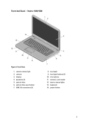
microphone 11. camera 3. Vostro 1540/1550 Figure 3. display 4. optical drive eject button 7. touchpad buttons (2) 10. camera status light 2. device status lights 13. power button 3 memory card reader 12. Front View 1. touchpad 9. speakers (2) 5. optical drive 6. keyboard 14. Front And Back - USB 2.0 connectors (2) 8.
microphone 11. camera 3. Vostro 1540/1550 Figure 3. display 4. optical drive eject button 7. touchpad buttons (2) 10. camera status light 2. device status lights 13. power button 3 memory card reader 12. Front View 1. touchpad 9. speakers (2) 5. optical drive 6. keyboard 14. Front And Back - USB 2.0 connectors (2) 8.
User Manual
Page 4
... 9. WARNING: The AC adapter works with the fan or the computer. Using an incompatible cable or improperly connecting the cable to accumulate in this section, read the safety information that shipped with your Dell computer in a low-airflow environment, such as a closed briefcase, while it is normal and does not indicate a problem with electrical outlets worldwide. security cable slot 2. Restricting the airflow...
... 9. WARNING: The AC adapter works with the fan or the computer. Using an incompatible cable or improperly connecting the cable to accumulate in this section, read the safety information that shipped with your Dell computer in a low-airflow environment, such as a closed briefcase, while it is normal and does not indicate a problem with electrical outlets worldwide. security cable slot 2. Restricting the airflow...
User Manual
Page 6
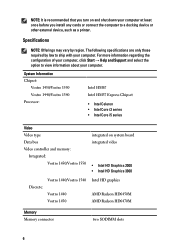
... information regarding the configuration of your computer, click Start → Help and Support and select the option to view information about your computer. System Information Chipset: Vostro 1450/Vostro 1550 Vostro 1440/Vostro 1540 Processor: Intel HM67 Intel HM57 Express Chipset • Intel Celeron • Intel Core i3 series • Intel Core i5 series Video Video type Data bus Video controller and memory: Integrated: Vostro 1450/Vostro 1550 integrated...
... information regarding the configuration of your computer, click Start → Help and Support and select the option to view information about your computer. System Information Chipset: Vostro 1450/Vostro 1550 Vostro 1440/Vostro 1540 Processor: Intel HM67 Intel HM57 Express Chipset • Intel Celeron • Intel Core i3 series • Intel Core i5 series Video Video type Data bus Video controller and memory: Integrated: Vostro 1450/Vostro 1550 integrated...
Owners Manual
Page 3
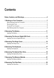
... Working Inside Your Computer 7 Recommended Tools...8 Turning Off Your Computer 9 After Working Inside Your Computer 9 2 Removing The Battery 11 Installing The Battery...11 3 Removing The Secure Digital (SD) Card 13 Installing The Secure Digital (SD) Card 14 4 Removing The Hinge Cover 15 Installing The Hinge Cover 16 5 Removing The Keyboard 17 Installing The Keyboard 18 6 Removing The Optical Disc Drive 19 Installing The Optical Disc Drive 20 7 Removing The Memory Module 21 Installing The Memory Module 22 8 Removing The Palm Rest 23 Installing...
... Working Inside Your Computer 7 Recommended Tools...8 Turning Off Your Computer 9 After Working Inside Your Computer 9 2 Removing The Battery 11 Installing The Battery...11 3 Removing The Secure Digital (SD) Card 13 Installing The Secure Digital (SD) Card 14 4 Removing The Hinge Cover 15 Installing The Hinge Cover 16 5 Removing The Keyboard 17 Installing The Keyboard 18 6 Removing The Optical Disc Drive 19 Installing The Optical Disc Drive 20 7 Removing The Memory Module 21 Installing The Memory Module 22 8 Removing The Palm Rest 23 Installing...
Owners Manual
Page 7
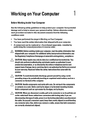
... authorized by Dell is not covered by your warranty. Hold a component such as a connector on the back of cable, press in reverse order. Unless otherwise noted, each procedure included in this type of the computer. WARNING: Before working inside your computer. • A component can be done by the online or telephone service and support team. Hold a card by its...
... authorized by Dell is not covered by your warranty. Hold a component such as a connector on the back of cable, press in reverse order. Unless otherwise noted, each procedure included in this type of the computer. WARNING: Before working inside your computer. • A component can be done by the online or telephone service and support team. Hold a card by its...
Owners Manual
Page 8
... harm internal components. 11. Turn off your computer from your computer, ground yourself by touching an unpainted metal surface, such as the optional Media Base or Battery Slice, undock it. Remove the main battery. 8. To avoid damaging your computer and all network cables from the appropriate slots. NOTE: To avoid damaging the system board, you must remove the main battery before opening the display. Open the display. 10...
... harm internal components. 11. Turn off your computer from your computer, ground yourself by touching an unpainted metal surface, such as the optional Media Base or Battery Slice, undock it. Remove the main battery. 8. To avoid damaging your computer and all network cables from the appropriate slots. NOTE: To avoid damaging the system board, you must remove the main battery before opening the display. Open the display. 10...
Owners Manual
Page 9
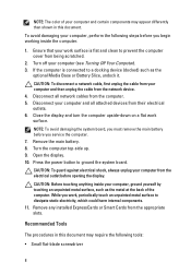
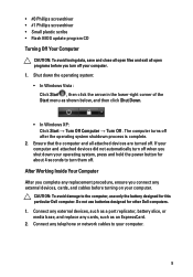
Ensure that the computer and all open programs before turning on your computer. 9 Connect any telephone or network cables to your computer. Connect any external devices, such as a port replicator, battery slice, or media base, and replace any external devices, cards, and cables before you shut down the operating system: • In Windows Vista : Click Start , then click the arrow in the lower-right corner of the Start menu as an ExpressCard. 2. CAUTION...
Ensure that the computer and all open programs before turning on your computer. 9 Connect any telephone or network cables to your computer. Connect any external devices, such as a port replicator, battery slice, or media base, and replace any external devices, cards, and cables before you shut down the operating system: • In Windows Vista : Click Start , then click the arrow in the lower-right corner of the Start menu as an ExpressCard. 2. CAUTION...
Owners Manual
Page 21
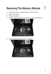
Remove the keyboard. 4. Pry the retention clips away from the computer. 21 Remove the battery. 3. Removing The Memory Module 7 1. Follow the procedures in Before Working On Your Computer. 2. Remove the memory module from the memory module until it pops up. 5.
Remove the keyboard. 4. Pry the retention clips away from the computer. 21 Remove the battery. 3. Removing The Memory Module 7 1. Follow the procedures in Before Working On Your Computer. 2. Remove the memory module from the memory module until it pops up. 5.
Owners Manual
Page 42
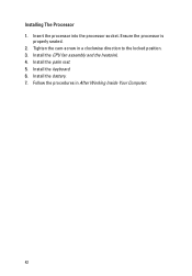
Install the CPU fan assembly and the heatsink. 4. Install the battery. 7. Install the palm rest. 5. Follow the procedures in a clockwise direction to the locked position. 3. Tighten the cam-screw in After Working Inside Your Computer. 42 Install the keyboard. 6. Ensure the processor is properly seated. 2. Installing The Processor 1. Insert the processor into the processor socket.
Install the CPU fan assembly and the heatsink. 4. Install the battery. 7. Install the palm rest. 5. Follow the procedures in a clockwise direction to the locked position. 3. Tighten the cam-screw in After Working Inside Your Computer. 42 Install the keyboard. 6. Ensure the processor is properly seated. 2. Installing The Processor 1. Insert the processor into the processor socket.
Owners Manual
Page 43
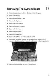
Follow the procedures in cable (2), USB board cable (3), speaker cable (4), audio board cable (5), and the coin-cell battery cable (6). 12. Remove the battery. 3. Remove the memory module. 7. Remove the palm rest. 8. Remove the SD memory card. 4. Remove the CPU fan assembly and the heatsink. 11. Remove the hard drive. 9. Remove the keyboard. 5. Remove the optical drive. 6. Disconnect the display cable (1), DC-in Before Working On Your Computer. 2. Remove the WLAN card. 10. Removing The System Board 17 1. Remove the screws that secure the system board. 43
Follow the procedures in cable (2), USB board cable (3), speaker cable (4), audio board cable (5), and the coin-cell battery cable (6). 12. Remove the battery. 3. Remove the memory module. 7. Remove the palm rest. 8. Remove the SD memory card. 4. Remove the CPU fan assembly and the heatsink. 11. Remove the hard drive. 9. Remove the keyboard. 5. Remove the optical drive. 6. Disconnect the display cable (1), DC-in Before Working On Your Computer. 2. Remove the WLAN card. 10. Removing The System Board 17 1. Remove the screws that secure the system board. 43
Owners Manual
Page 45
Install the CPU fan assembly and the heatsink . 6. Install the battery. 14. Connect the LCD cable, DC-in After Working Inside Your Computer. 45 Install the hard drive. 8. Installing The System Board 1. Install the SD memory card. 13. Install the processor. 5. Follow the procedures in cable, USB board cable, audio board cable, coin-cell battery cable, and the speaker cable. 4. Install the keyboard. 12. Install the WLAN card. 7. Install the palm rest. 9. Install the optical drive. 11. Insert the system board with the LAN, VGA, HDMI, and USB connectors into...
Install the CPU fan assembly and the heatsink . 6. Install the battery. 14. Connect the LCD cable, DC-in After Working Inside Your Computer. 45 Install the hard drive. 8. Installing The System Board 1. Install the SD memory card. 13. Install the processor. 5. Follow the procedures in cable, USB board cable, audio board cable, coin-cell battery cable, and the speaker cable. 4. Install the keyboard. 12. Install the WLAN card. 7. Install the palm rest. 9. Install the optical drive. 11. Insert the system board with the LAN, VGA, HDMI, and USB connectors into...
Owners Manual
Page 47
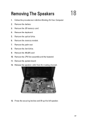
Remove the hard drive. 9. Release the speaker cable from the routing channel. 18 13. Follow the procedures in Before Working On Your Computer. 2. Remove the SD memory card. 4. Press the securing latches and lift up the left speaker. 47 Remove the memory module. 7. Remove the system board. 12. Remove the keyboard. 5. Remove the battery. 3. Remove the optical drive. 6. Remove the WLAN card. 10. Remove the CPU fan assembly and the heatsink. 11. Remove the palm rest. 8. Removing The Speakers 1.
Remove the hard drive. 9. Release the speaker cable from the routing channel. 18 13. Follow the procedures in Before Working On Your Computer. 2. Remove the SD memory card. 4. Press the securing latches and lift up the left speaker. 47 Remove the memory module. 7. Remove the system board. 12. Remove the keyboard. 5. Remove the battery. 3. Remove the optical drive. 6. Remove the WLAN card. 10. Remove the CPU fan assembly and the heatsink. 11. Remove the palm rest. 8. Removing The Speakers 1.

Owners Manual
Page 71
... change a user-selectable option such as the user password. • read the current amount of memory or set the type of hard drive installed. Press < Left Arrow > and < Right Arrow > keys to access the System Setup options. When the blue DELL logo is displayed, you must watch for it is highlighted, the Options List lists the options that the keyboard has initialized. Certain changes can appear very quickly, so you to access the System Setup options. As a Menu option...
... change a user-selectable option such as the user password. • read the current amount of memory or set the type of hard drive installed. Press < Left Arrow > and < Right Arrow > keys to access the System Setup options. When the blue DELL logo is displayed, you must watch for it is highlighted, the Options List lists the options that the keyboard has initialized. Certain changes can appear very quickly, so you to access the System Setup options. As a Menu option...

Owners Manual
Page 72
... in the Options List . As a Menu option is highlighted, the Options List lists the options that define the hardware installed on your current settings. Appears on the computer's internal calendar. 72 Press to return to navigate. or + Change existing item value. < Enter > Select the sub menu or execute command. < F9 > Load setup default. < F10 > Save current configuration and exit System Setup. System Setup Options Main System Information System Date Displays the computer model number.
... in the Options List . As a Menu option is highlighted, the Options List lists the options that define the hardware installed on your current settings. Appears on the computer's internal calendar. 72 Press to return to navigate. or + Change existing item value. < Enter > Select the sub menu or execute command. < F9 > Load setup default. < F10 > Save current configuration and exit System Setup. System Setup Options Main System Information System Date Displays the computer model number.

Owners Manual
Page 73
... the optical drive. Displays the memory installed on -board network card. 73 Displays the processor L3 cache size. Displays the memory speed. Displays the model number and capacity of your computer. Enable or disable the Intel Default: Enabled SpeedStep feature. Displays the BIOS revision. Enable or disable the power Default: Enabled supply to the on the computer. Displays the speed of your computer (if available). Displays the service tag of the processor. Displays the model number and capacity of the hard drive.
... the optical drive. Displays the memory installed on -board network card. 73 Displays the processor L3 cache size. Displays the memory speed. Displays the model number and capacity of your computer. Enable or disable the Intel Default: Enabled SpeedStep feature. Displays the BIOS revision. Enable or disable the power Default: Enabled supply to the on the computer. Displays the speed of your computer (if available). Displays the service tag of the processor. Displays the model number and capacity of the hard drive.

Owners Manual
Page 74
... controller Default: AHCI mode to set , this field can be charged when connected to enter it. If the service tag is connected. USB Emulation USB Wake Support SATA Operation Adapter Warnings Function Key Behavior Charger Behavior Miscellaneous Devices Enable or disable the USB Default: Enabled emulation feature. Default: Function key first Specifies if the computer battery will be used to an AC power source. This feature is enabled only when the AC adapter is not already set a password on the computer's internal hard drive (HDD). Allows USB devices...
... controller Default: AHCI mode to set , this field can be charged when connected to enter it. If the service tag is connected. USB Emulation USB Wake Support SATA Operation Adapter Warnings Function Key Behavior Charger Behavior Miscellaneous Devices Enable or disable the USB Default: Enabled emulation feature. Default: Function key first Specifies if the computer battery will be used to an AC power source. This feature is enabled only when the AC adapter is not already set a password on the computer's internal hard drive (HDD). Allows USB devices...
Owners Manual
Page 77
... power button. Code Cause and Troubleshooting Steps 1 BIOS ROM checksum in progress or failure System board failure, covers BIOS corruption or ROM error 2 No RAM detected No memory detected 3 Chipset Error (North and South Bridge Chipset, DMA/IMR/ Timer Error) , Time-Of-Day Clock test failure , Gate A20 failure , Super I/O chip failure , Keyboard controller test failure System board failure 4 RAM Read/Write failure Memory failure 5 Real-time clock power fail CMOS battery failure 6 Video BIOS...
... power button. Code Cause and Troubleshooting Steps 1 BIOS ROM checksum in progress or failure System board failure, covers BIOS corruption or ROM error 2 No RAM detected No memory detected 3 Chipset Error (North and South Bridge Chipset, DMA/IMR/ Timer Error) , Time-Of-Day Clock test failure , Gate A20 failure , Super I/O chip failure , Keyboard controller test failure System board failure 4 RAM Read/Write failure Memory failure 5 Real-time clock power fail CMOS battery failure 6 Video BIOS...
Owners Manual
Page 79
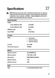
... configuration of your computer, click Start → Help and Support and select the option to view information about your computer. Specifications 27 NOTE: Offerings may vary by law to ship with your computer. System Information Chipset Vostro 1450/Vostro 1550 Vostro 1440/Vostro 1540 DRAM bus width Flash EPROM Intel HM67 Intel HM57 64-bit SPI 32 Mbits Processor Types L2 cache External...
... configuration of your computer, click Start → Help and Support and select the option to view information about your computer. Specifications 27 NOTE: Offerings may vary by law to ship with your computer. System Information Chipset Vostro 1450/Vostro 1550 Vostro 1440/Vostro 1540 DRAM bus width Flash EPROM Intel HM67 Intel HM57 64-bit SPI 32 Mbits Processor Types L2 cache External...


