Setup and Quick Reference Guide
Page 4
3 Specifications 23 4 Troubleshooting 35 Tools 35 Power Lights 35 Beep Codes 35 Error Messages 37 Dell Diagnostics 42 Solving Problems 44 Power Problems 45 Memory Problems 46 Lockups and Software Problems 47 Dell™ Technical Update Service 49 Dell Support Utility 49 5 Reinstalling Software 51 Drivers 51 Identifying Drivers 51 Reinstalling Drivers and Utilities 51 Restoring Your Operating System 54 Using Microsoft Windows System Restore . . . . . 54 Using Dell™ PC Restore and Dell Factory Image Restore 56 Using the Operating System Media 59 4 Contents
3 Specifications 23 4 Troubleshooting 35 Tools 35 Power Lights 35 Beep Codes 35 Error Messages 37 Dell Diagnostics 42 Solving Problems 44 Power Problems 45 Memory Problems 46 Lockups and Software Problems 47 Dell™ Technical Update Service 49 Dell Support Utility 49 5 Reinstalling Software 51 Drivers 51 Identifying Drivers 51 Reinstalling Drivers and Utilities 51 Restoring Your Operating System 54 Using Microsoft Windows System Restore . . . . . 54 Using Dell™ PC Restore and Dell Factory Image Restore 56 Using the Operating System Media 59 4 Contents

Setup and Quick Reference Guide
Page 24
ExpressCard (continued) ExpressCard connector Cards supported ExpressCard connector size • 54-mm ExpressCard slot (supports both memory slots must be populated. NOTE: The available memory displayed does not reflect the complete maximum memory installed because some memory is reserved for system files. 24 Specifications and PCIe-based interfaces) ExpressCard/54 (54 mm) (2.126 inches) 54...
ExpressCard (continued) ExpressCard connector Cards supported ExpressCard connector size • 54-mm ExpressCard slot (supports both memory slots must be populated. NOTE: The available memory displayed does not reflect the complete maximum memory installed because some memory is reserved for system files. 24 Specifications and PCIe-based interfaces) ExpressCard/54 (54 mm) (2.126 inches) 54...

Setup and Quick Reference Guide
Page 26
... Speaker Internal speaker amplifier Volume controls Vostro 1310 and 1510 discrete: • NVIDIA GeForce 8400M GS, 64 bit Vostro 1710 discrete: • NVIDIA GeForce 8600M GS, 128 bit Vostro 1310, 1510, and 1710 integrated: • up to 256 MB of shared memory Vostro 1310 discrete: • 128 MB Vostro 1510 discrete: • 256 MB Vostro 1710 discrete: • 256 MB...
... Speaker Internal speaker amplifier Volume controls Vostro 1310 and 1510 discrete: • NVIDIA GeForce 8400M GS, 64 bit Vostro 1710 discrete: • NVIDIA GeForce 8600M GS, 128 bit Vostro 1310, 1510, and 1710 integrated: • up to 256 MB of shared memory Vostro 1310 discrete: • 128 MB Vostro 1510 discrete: • 256 MB Vostro 1710 discrete: • 256 MB...
Setup and Quick Reference Guide
Page 35
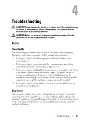
If the power light is blinking amber, the computer is receiving electrical power, a device such as a memory module or graphics card might emit a series of beeps during start-up if the monitor cannot display errors or problems. This series of repetitive three ...
If the power light is blinking amber, the computer is receiving electrical power, a device such as a memory module or graphics card might emit a series of beeps during start-up if the monitor cannot display errors or problems. This series of repetitive three ...

Setup and Quick Reference Guide
Page 36
...Write down the beep code. 2 Run the Dell Diagnostics to identify a more memory modules are compatible with your Service Manual at support.dell.com). 3 If the problem persists, contact Dell. 3 Possible system Contact Dell. Possible motherboard failure. 2 No memory modules 1 If you have two or more...have identified a faulty module or reinstalled all modules without error. 2 If available, install good memory of the same type into your computer see your computer (see "Dell Diagnostics" on page 42). If the computer starts normally, reinstall an additional module. Code ...
...Write down the beep code. 2 Run the Dell Diagnostics to identify a more memory modules are compatible with your Service Manual at support.dell.com). 3 If the problem persists, contact Dell. 3 Possible system Contact Dell. Possible motherboard failure. 2 No memory modules 1 If you have two or more...have identified a faulty module or reinstalled all modules without error. 2 If available, install good memory of the same type into your computer see your computer (see "Dell Diagnostics" on page 42). If the computer starts normally, reinstall an additional module. Code ...

Setup and Quick Reference Guide
Page 37
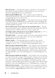
... touch pad or external mouse may be faulty. See your Service Manual failure. If the problem persists, contact Dell (see "Contacting Dell" on page 69). DATA ERROR - Reinstall the memory modules and, if necessary, replace them. DI S K C : F A I L U R E - For an external mouse, check the cable connection. C A C H E D I S A B L E D D U E T O F A I L E D INITIALIZATION - The hard drive failed initialization. Possible at...
... touch pad or external mouse may be faulty. See your Service Manual failure. If the problem persists, contact Dell (see "Contacting Dell" on page 69). DATA ERROR - Reinstall the memory modules and, if necessary, replace them. DI S K C : F A I L U R E - For an external mouse, check the cable connection. C A C H E D I S A B L E D D U E T O F A I L E D INITIALIZATION - The hard drive failed initialization. Possible at...
Setup and Quick Reference Guide
Page 38
... The file that you are trying to copy is full. A memory module may be loose. See your Service Manual at support.dell.com for example, Printer out of memory recorded in nonvolatile memory (NVRAM) does not match the memory installed in the bay before it can continue. Take the appropriate ... 42). Shut down the computer, remove the hard drive (see your Service Manual at support.dell.com), and boot the computer from the computer. Install a hard drive in filenames. Reinstall the memory modules and, if necessary, replace them. The operation requires a hard drive in the computer....
... The file that you are trying to copy is full. A memory module may be loose. See your Service Manual at support.dell.com for example, Printer out of memory recorded in nonvolatile memory (NVRAM) does not match the memory installed in the bay before it can continue. Take the appropriate ... 42). Shut down the computer, remove the hard drive (see your Service Manual at support.dell.com), and boot the computer from the computer. Install a hard drive in filenames. Reinstall the memory modules and, if necessary, replace them. The operation requires a hard drive in the computer....
Setup and Quick Reference Guide
Page 39
..." on page 42). Run the Keyboard Controller test in the Dell Diagnostics (see "Dell Diagnostics" on page 42). K E Y B O A R D S T U C K KEY F A I L U R E - The hard drive may be played. The operating system is installed. HA R D - K E Y B O A R D D A T A L I N E F A I L U R E - Troubleshooting 39 K E Y B O A R D C L O C K L I N E F A I L U R E - The message is most likely to occur after a memory module is trying to boot to nonbootable media, such as a floppy...
..." on page 42). Run the Keyboard Controller test in the Dell Diagnostics (see "Dell Diagnostics" on page 42). K E Y B O A R D S T U C K KEY F A I L U R E - The hard drive may be played. The operating system is installed. HA R D - K E Y B O A R D D A T A L I N E F A I L U R E - Troubleshooting 39 K E Y B O A R D C L O C K L I N E F A I L U R E - The message is most likely to occur after a memory module is trying to boot to nonbootable media, such as a floppy...
Setup and Quick Reference Guide
Page 40
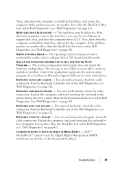
..., if necessary, replace them . Run the System Set tests in the Dell Diagnostics (see "Dell Diagnostics" on the system board may be faulty or improperly seated. A memory module may be malfunctioning. If the error message still appears, see "Contacting Dell" on page 69). MEMORY WRITE/READ FAILURE AT ADDRESS, READ VALUE EXPECTING VALUE - N O T I M E R T I C K I L A B L E - A chip on...
..., if necessary, replace them . Run the System Set tests in the Dell Diagnostics (see "Dell Diagnostics" on the system board may be faulty or improperly seated. A memory module may be malfunctioning. If the error message still appears, see "Contacting Dell" on page 69). MEMORY WRITE/READ FAILURE AT ADDRESS, READ VALUE EXPECTING VALUE - N O T I M E R T I C K I L A B L E - A chip on...

Setup and Quick Reference Guide
Page 42
... this section, follow the safety instructions that supports the system configuration settings may be loose. Run the System Memory tests and the Keyboard Controller test in the Dell Diagnostics (see "Contacting Dell" on page 69). A chip on page 42). If the problem persists, contact Dell (see "Dell Diagnostics" on the system board may require recharging.
... this section, follow the safety instructions that supports the system configuration settings may be loose. Run the System Memory tests and the Keyboard Controller test in the Dell Diagnostics (see "Contacting Dell" on page 69). A chip on page 42). If the problem persists, contact Dell (see "Dell Diagnostics" on the system board may require recharging.
Setup and Quick Reference Guide
Page 45
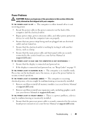
...front panel cable are turned on. • Ensure that the electrical outlet is working by testing it with your Service Manual at support.dell.com). Troubleshooting 45 Power Problems CAUTION: Before you begin any of the computer and the electrical outlet. • Bypass power strips, ...). There is a power problem, a device may be malfunctioning or incorrectly installed. • Remove and then reinstall all memory modules (see your Service Manual at support.dell.com). • Remove and then reinstall any power strips being used are plugged into an electrical outlet and are securely...
...front panel cable are turned on. • Ensure that the electrical outlet is working by testing it with your Service Manual at support.dell.com). Troubleshooting 45 Power Problems CAUTION: Before you begin any of the computer and the electrical outlet. • Bypass power strips, ...). There is a power problem, a device may be malfunctioning or incorrectly installed. • Remove and then reinstall all memory modules (see your Service Manual at support.dell.com). • Remove and then reinstall any power strips being used are plugged into an electrical outlet and are securely...
Setup and Quick Reference Guide
Page 46
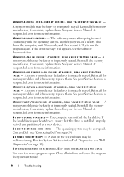
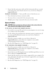
... to the system board connector (see your Service Manual at support.dell.com) to ensure that your computer is successfully communicating with your computer, see "Memory" on page 24. • Run the Dell Diagnostics (see "Dell Diagnostics" on page 42). For more information about the type of... the procedures in this section, follow the safety information that shipped with the memory. • Run the Dell Diagnostics (see "Dell Diagnostics" on page 42). 46 Troubleshooting IF YOU RECEIVE AN INSUFFICIENT MEMORY MESSAGE - • Save and close any open files and exit any open programs...
... to the system board connector (see your Service Manual at support.dell.com) to ensure that your computer is successfully communicating with your computer, see "Memory" on page 24. • Run the Dell Diagnostics (see "Dell Diagnostics" on page 42). For more information about the type of... the procedures in this section, follow the safety information that shipped with the memory. • Run the Dell Diagnostics (see "Dell Diagnostics" on page 42). 46 Troubleshooting IF YOU RECEIVE AN INSUFFICIENT MEMORY MESSAGE - • Save and close any open files and exit any open programs...
Setup and Quick Reference Guide
Page 71
... identifying, 51 reinstalling, 51 Drivers and Utilities media, 52 Dell Diagnostics, 42 E ergonomics information, 62 error messages, 37 beep codes, 35 F Factory Image Restore, 56, 58 Files and Settings Transfer Wizard, 19 H hardware beep codes, 35 Dell Diagnostics, 42 I Internet connection about, 17 options, 17 setting up, 18 M memory troubleshooting, 46 Index 71
... identifying, 51 reinstalling, 51 Drivers and Utilities media, 52 Dell Diagnostics, 42 E ergonomics information, 62 error messages, 37 beep codes, 35 F Factory Image Restore, 56, 58 Files and Settings Transfer Wizard, 19 H hardware beep codes, 35 Dell Diagnostics, 42 I Internet connection about, 17 options, 17 setting up, 18 M memory troubleshooting, 46 Index 71

Setup and Quick Reference Guide
Page 72
..., 62 setup, 15 software reinstalling, 51 troubleshooting, 48 specifications, 23 Starting the Dell Diagnostics From the Drivers and Utilities Media, 44 Starting the Dell Diagnostics From Your Hard Drive, 43 support contacting Dell, 69 System Restore, 54 T Technical Update Service, 49 transferring information to a new... computer, 19 troubleshooting, 35 beep codes, 35 blue screen, 48 computer stops responding, 47 Dell Diagnostics, 42 error messages, 37 lockups, 47 memory, 46 power, 45 power light conditions, 45 power lights, 35 programs and Windows compatibility, 48 restore to previous...
..., 62 setup, 15 software reinstalling, 51 troubleshooting, 48 specifications, 23 Starting the Dell Diagnostics From the Drivers and Utilities Media, 44 Starting the Dell Diagnostics From Your Hard Drive, 43 support contacting Dell, 69 System Restore, 54 T Technical Update Service, 49 transferring information to a new... computer, 19 troubleshooting, 35 beep codes, 35 blue screen, 48 computer stops responding, 47 Dell Diagnostics, 42 error messages, 37 lockups, 47 memory, 46 power, 45 power light conditions, 45 power lights, 35 programs and Windows compatibility, 48 restore to previous...
Setup and Features Information Tech Sheet
Page 8
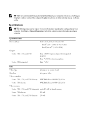
...For more information regarding the configuration of shared memory Vostro 1310 discrete 128 MB Vostro 1510, 1710, and 2510 discrete 256 MB Specifications NOTE: Offerings may vary by region. System Information Processor type Chipset Vostro 1310, 1510, and 1710 Vostro 2510 integrated Vostro 1310, 1510, 1710 and 2510: Intel® Core&#...on system board Data bus integrated video Video controller Vostro 1310, 1510, and 2510 discrete NVIDIA GeForce 8400M GS, 64 bit Vostro 1710 discrete NVIDIA GeForce 8600M GS, 128 bit Video memory Vostro 1310, 1510, and 1710 integrated up to 256 MB of ...
...For more information regarding the configuration of shared memory Vostro 1310 discrete 128 MB Vostro 1510, 1710, and 2510 discrete 256 MB Specifications NOTE: Offerings may vary by region. System Information Processor type Chipset Vostro 1310, 1510, and 1710 Vostro 2510 integrated Vostro 1310, 1510, 1710 and 2510: Intel® Core&#...on system board Data bus integrated video Video controller Vostro 1310, 1510, and 2510 discrete NVIDIA GeForce 8400M GS, 64 bit Vostro 1710 discrete NVIDIA GeForce 8600M GS, 128 bit Video memory Vostro 1310, 1510, and 1710 integrated up to 256 MB of ...
Service Manual
Page 1
...tells you how to either the entities claiming the marks and names or their products. All rights reserved. Dell Inc. Dell™ Vostro™ 1510 Service Manual Troubleshooting Before Working on Your Computer Hard Drive Wireless Local Area Network (WLAN) Card Fan ...Processor Thermal-Cooling Assembly Processor Module Memory Hinge Cover Keyboard Power Button and Multimedia Button Pads Display Palm Rest Fingerprint Reader...
...tells you how to either the entities claiming the marks and names or their products. All rights reserved. Dell Inc. Dell™ Vostro™ 1510 Service Manual Troubleshooting Before Working on Your Computer Hard Drive Wireless Local Area Network (WLAN) Card Fan ...Processor Thermal-Cooling Assembly Processor Module Memory Hinge Cover Keyboard Power Button and Multimedia Button Pads Display Palm Rest Fingerprint Reader...
Service Manual
Page 2
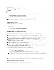
... the following tools: l Small flat-blade screwdriver l Phillips screwdriver l Small plastic scribe l Flash BIOS update (see the Dell Support website at support.dell.com) What You Need to Know for Your Safety Use the following safety guidelines to help protect your own personal safety. ...that shipped with care. Back to Contents Page Before Working on Your Computer Dell™ Vostro™ 1510 Service Manual Recommended Tools What You Need to prevent the computer cover from the ExpressCard slot and the 8-in-1 memory card reader. l When replacing a component, you cannot shut down your...
... the following tools: l Small flat-blade screwdriver l Phillips screwdriver l Small plastic scribe l Flash BIOS update (see the Dell Support website at support.dell.com) What You Need to Know for Your Safety Use the following safety guidelines to help protect your own personal safety. ...that shipped with care. Back to Contents Page Before Working on Your Computer Dell™ Vostro™ 1510 Service Manual Recommended Tools What You Need to prevent the computer cover from the ExpressCard slot and the 8-in-1 memory card reader. l When replacing a component, you cannot shut down your...
Service Manual
Page 10
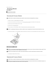
...perpendicular to the cam stop. 1 ZIF-socket cam screw 2 ZIF socket NOTICE: To ensure maximum cooling for an illustration of the memory cover.) 3. Lift the processor module from the ZIF socket. Replacing the Processor Module CAUTION: Before you begin the following procedure, ... the module straight up. The oils in Before Working on the processor module. 7. Back to Contents Page Processor Module Dell™ Vostro™ 1510 Service Manual Removing the Processor Module Replacing the Processor Module Removing the Processor Module CAUTION: Before you begin the following procedure...
...perpendicular to the cam stop. 1 ZIF-socket cam screw 2 ZIF socket NOTICE: To ensure maximum cooling for an illustration of the memory cover.) 3. Lift the processor module from the ZIF socket. Replacing the Processor Module CAUTION: Before you begin the following procedure, ... the module straight up. The oils in Before Working on the processor module. 7. Back to Contents Page Processor Module Dell™ Vostro™ 1510 Service Manual Removing the Processor Module Replacing the Processor Module Removing the Processor Module CAUTION: Before you begin the following procedure...
Service Manual
Page 11
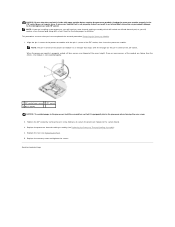
Replace the memory cover and tighten the screws. Back to the system board. 3. NOTICE: Ensure that the cam lock is properly seated, all four corners are aligned at ...
Replace the memory cover and tighten the screws. Back to the system board. 3. NOTICE: Ensure that the cam lock is properly seated, all four corners are aligned at ...
Service Manual
Page 12
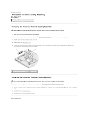
... Thermal-Cooling Assembly. 1. Replace the fan (see Removing the Fan). 5. Back to Contents Page Slide the cover out of the memory cover.) 3. Align the six captive screws on the processor thermal-cooling assembly with the screw holes on Your Computer. 2. Follow the... on the system board and tighten the screws in sequential order. 2. Back to Contents Page Processor Thermal-Cooling Assembly Dell™ Vostro™ 1510 Service Manual Removing the Processor Thermal-Cooling Assembly Replacing the Processor Thermal-Cooling Assembly Removing the Processor Thermal-Cooling Assembly CAUTION...
... Thermal-Cooling Assembly. 1. Replace the fan (see Removing the Fan). 5. Back to Contents Page Slide the cover out of the memory cover.) 3. Align the six captive screws on the processor thermal-cooling assembly with the screw holes on Your Computer. 2. Follow the... on the system board and tighten the screws in sequential order. 2. Back to Contents Page Processor Thermal-Cooling Assembly Dell™ Vostro™ 1510 Service Manual Removing the Processor Thermal-Cooling Assembly Replacing the Processor Thermal-Cooling Assembly Removing the Processor Thermal-Cooling Assembly CAUTION...


