User Guide
Page 3
... and Controls 7 Monitor Specifications 10 Plug-and-Play 21 LCD Monitor Quality and Pixel Policy 21 Setting Up the Monitor 22 Installing the Arm 22 Organizing Your Cables 29 Using the Tilt, Swivel, Pivot, Vertical and Horizontal Extension 30 Adjusting the Rotation Display Settings of Your System... 32 Connecting Your Monitor 33 Removing the Monitor Arm 36 Wall Mounting (Optional 37 Operating the Monitor 38 Turning on the Monitor 38 Using the Front Panel Controls 38 Using the On...
... and Controls 7 Monitor Specifications 10 Plug-and-Play 21 LCD Monitor Quality and Pixel Policy 21 Setting Up the Monitor 22 Installing the Arm 22 Organizing Your Cables 29 Using the Tilt, Swivel, Pivot, Vertical and Horizontal Extension 30 Adjusting the Rotation Display Settings of Your System... 32 Connecting Your Monitor 33 Removing the Monitor Arm 36 Wall Mounting (Optional 37 Operating the Monitor 38 Turning on the Monitor 38 Using the Front Panel Controls 38 Using the On...

User Guide
Page 5
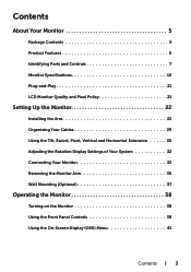
NOTE: Some items may not ship with the components shown below. Monitor Arm riser Arm base Allen key Power cable (varies by country) About Your Monitor | 5 Make sure that you have received all the components and contact Dell if something is missing. About Your Monitor Package Contents Your monitor ships with your monitor. Some features or media may not be optional and may be available in certain countries.
NOTE: Some items may not ship with the components shown below. Monitor Arm riser Arm base Allen key Power cable (varies by country) About Your Monitor | 5 Make sure that you have received all the components and contact Dell if something is missing. About Your Monitor Package Contents Your monitor ships with your monitor. Some features or media may not be optional and may be available in certain countries.
User Guide
Page 8
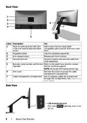
...x 100 mm-behind attached VESA compatible wall mount kit (100 mm x 100 cover) mm). 2 Regulatory label Lists the regulatory approvals. 3 Arm release button Release arm from monitor. 4 Security lock slot Secures monitor with lightning icon is for technical support. Back View Label Description Use 1 VESA mountiong holes (...100 mm Wall mount monitor using VESA- NOTE: All except APJ having service tag. 6 Arm cover Remove the cover to access the cable management compartment. 7 Cable management compartment Use to contact Tag label...
...x 100 mm-behind attached VESA compatible wall mount kit (100 mm x 100 cover) mm). 2 Regulatory label Lists the regulatory approvals. 3 Arm release button Release arm from monitor. 4 Security lock slot Secures monitor with lightning icon is for technical support. Back View Label Description Use 1 VESA mountiong holes (...100 mm Wall mount monitor using VESA- NOTE: All except APJ having service tag. 6 Arm cover Remove the cover to access the cable management compartment. 7 Cable management compartment Use to contact Tag label...

User Guide
Page 9
...: Remove the rubber plug when use the USB downstream connectors on the monitor. Connect the USB cable that comes with mDP to the computer. Arm lock Lock the arm to playback audio coming through HDMI or DP audio channels. DP connector (out) DP output for DP MST Function". Once this connector after...
...: Remove the rubber plug when use the USB downstream connectors on the monitor. Connect the USB cable that comes with mDP to the computer. Arm lock Lock the arm to playback audio coming through HDMI or DP audio channels. DP connector (out) DP output for DP MST Function". Once this connector after...
User Guide
Page 12
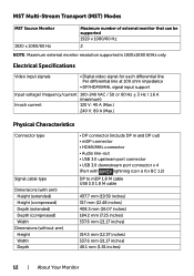
...; 3 Hz / 1.6 A (maximum) Inrush current 120 V: 40 A (Max.) 240 V: 80 A (Max.) Physical Characteristics Connector type Signal cable type Dimensions (with arm) Height (extended) Height (compressed) Depth (extended) Depth (compressed) Width Dimensions (without arm) Height Width Depth • DP connector (include DP in and DP out) • mDP connector • HDMI/MHL connector •...
...; 3 Hz / 1.6 A (maximum) Inrush current 120 V: 40 A (Max.) 240 V: 80 A (Max.) Physical Characteristics Connector type Signal cable type Dimensions (with arm) Height (extended) Height (compressed) Depth (extended) Depth (compressed) Width Dimensions (without arm) Height Width Depth • DP connector (include DP in and DP out) • mDP connector • HDMI/MHL connector •...

User Guide
Page 13
... Width Depth Weight Weight with packaging Weight with arm assembly and cables Weight without arm assembly (For wall mount or VESA mount considerations - no cables) Weight of arm assembly 441.6 mm (17.39 inches) 121.6 mm (4.79 inches) 384.3 mm (15.13 inches) 8.2 kg (18.08 lb) 5.9 kg (13.01 lb) 3.2 kg (7.05...
... Width Depth Weight Weight with packaging Weight with arm assembly and cables Weight without arm assembly (For wall mount or VESA mount considerations - no cables) Weight of arm assembly 441.6 mm (17.39 inches) 121.6 mm (4.79 inches) 384.3 mm (15.13 inches) 8.2 kg (18.08 lb) 5.9 kg (13.01 lb) 3.2 kg (7.05...

User Guide
Page 22
...; Install the 2 screws either on top row or the bottom row of table configurations which the arm base could be installed: A. For other mounting solutions (optional), please refer to the arm shipped with the monitor. Table with open edge B. Others A. Table with partition with grommet hole ...D. Table with gap between C. Setting Up the Monitor Installing the Arm NOTE: The arm riser and arm base are a few types of arm base bracket depending on the table thickness. • Insert the clamp bracket key holes to the screws and slide...
...; Install the 2 screws either on top row or the bottom row of table configurations which the arm base could be installed: A. For other mounting solutions (optional), please refer to the arm shipped with the monitor. Table with open edge B. Others A. Table with partition with grommet hole ...D. Table with gap between C. Setting Up the Monitor Installing the Arm NOTE: The arm riser and arm base are a few types of arm base bracket depending on the table thickness. • Insert the clamp bracket key holes to the screws and slide...

User Guide
Page 23
• Slide the arm base assembly completely into the table. • Tighten the thumbscrew until the clamp disc is fully in contact with gap between • Insert the arm base bracket through the gap between table and partition. Setting Up the Monitor | 23 B. Table with partition with the underside of table.
• Slide the arm base assembly completely into the table. • Tighten the thumbscrew until the clamp disc is fully in contact with gap between • Insert the arm base bracket through the gap between table and partition. Setting Up the Monitor | 23 B. Table with partition with the underside of table.
User Guide
Page 24
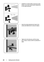
• Install the 2 screws either on top row or the bottom row of arm base bracket depending on the table thickness. • Insert the clamp bracket key holes to the screws and slide down to secure in place. • Tighten the thumbscrew until the clamp disc is fully in contact with the underside of table. 24 | Setting Up the Monitor
• Install the 2 screws either on top row or the bottom row of arm base bracket depending on the table thickness. • Insert the clamp bracket key holes to the screws and slide down to secure in place. • Tighten the thumbscrew until the clamp disc is fully in contact with the underside of table. 24 | Setting Up the Monitor

User Guide
Page 25
C. Setting Up the Monitor | 25 Table with grommet hole • Insert the arm base bracket through the grommet hole. • Install the 2 screws either on top row or the bottom row of arm base bracket depending on the table thickness. • Insert the clamp bracket key holes to the screws and slide down to secure in place.
C. Setting Up the Monitor | 25 Table with grommet hole • Insert the arm base bracket through the grommet hole. • Install the 2 screws either on top row or the bottom row of arm base bracket depending on the table thickness. • Insert the clamp bracket key holes to the screws and slide down to secure in place.

User Guide
Page 26
... might cause obstruction to be opened first before inserting the arm base bracket into the gap. In certain cases, the swing-open panel for cable management. D. C. However, the height of table. B. A. The panel need to the arm base installation as illustrated below. Without opening the panel, ...the gap is fully in contact with the underside of the arm base pole obstructs the panel from closing back. 26 | Setting Up the Monitor •...
... might cause obstruction to be opened first before inserting the arm base bracket into the gap. In certain cases, the swing-open panel for cable management. D. C. However, the height of table. B. A. The panel need to the arm base installation as illustrated below. Without opening the panel, ...the gap is fully in contact with the underside of the arm base pole obstructs the panel from closing back. 26 | Setting Up the Monitor •...

User Guide
Page 27
The recommended arm base installation steps to the arm base bracket. C. Remove the pole from the arm base by removing the center screw. Setting Up the Monitor | 27 Open the panel and insert the arm base bracket through the gap. B. Close the panel and install back the pole to overcome this issue: A.
The recommended arm base installation steps to the arm base bracket. C. Remove the pole from the arm base by removing the center screw. Setting Up the Monitor | 27 Open the panel and insert the arm base bracket through the gap. B. Close the panel and install back the pole to overcome this issue: A.

User Guide
Page 28
Installing the Arm Riser • Insert the arm riser fully into the pole of the arm base which has been installed to the table. • Fully tighten the set screw using the Allen key to prevent the arm riser accidentally detaching from the arm base. • Place the grooves on the back of monitor into the two tabs on the top part of the arm. • Tilt the monitor down till the monitor snaps into its place. 28 | Setting Up the Monitor
Installing the Arm Riser • Insert the arm riser fully into the pole of the arm base which has been installed to the table. • Fully tighten the set screw using the Allen key to prevent the arm riser accidentally detaching from the arm base. • Place the grooves on the back of monitor into the two tabs on the top part of the arm. • Tilt the monitor down till the monitor snaps into its place. 28 | Setting Up the Monitor

User Guide
Page 29
.... Flip the cable bracket up through the cable clips and bracket. • The cables should exit from the arm bottom opening and connected to the respective connectors on top of each other. • Attach the arm cover. NOTE: Ensure the cables do not overlap on the monitor. 1. Remove the... arm cover which is locked in position. • Thread the cables from bottom up until it is attached with magnets to ...
.... Flip the cable bracket up through the cable clips and bracket. • The cables should exit from the arm bottom opening and connected to the respective connectors on top of each other. • Attach the arm cover. NOTE: Ensure the cables do not overlap on the monitor. 1. Remove the... arm cover which is locked in position. • Thread the cables from bottom up until it is attached with magnets to ...

User Guide
Page 30
Using the Tilt, Swivel, Pivot, Vertical and Horizontal Extension NOTE: This is applicable to their respective set up instructions. For other mounting solutions please refer to the arm shipped with this monitor. Tilt and Vertical Extension With arm attached to the monitor, you can tilt and lift the monitor to the most comfortable viewing position. 30 | Setting Up the Monitor
Using the Tilt, Swivel, Pivot, Vertical and Horizontal Extension NOTE: This is applicable to their respective set up instructions. For other mounting solutions please refer to the arm shipped with this monitor. Tilt and Vertical Extension With arm attached to the monitor, you can tilt and lift the monitor to the most comfortable viewing position. 30 | Setting Up the Monitor

User Guide
Page 31
Pivoting Before you pivot the monitor, your Dell computer, you require an updated graphics driver that is not included with your monitor should be fully lifted vertically and fully tilted up to avoid ... (Landscape versus Portrait view) with this monitor. Swivel and Horizontal Extension With arm attached to the monitor, you can swivel the monitor and pan the arm to a optimum monitor viewing distance or just simply to compact the monitor to www.dell.com/support and see the Download section for Video Drivers for latest...
Pivoting Before you pivot the monitor, your Dell computer, you require an updated graphics driver that is not included with your monitor should be fully lifted vertically and fully tilted up to avoid ... (Landscape versus Portrait view) with this monitor. Swivel and Horizontal Extension With arm attached to the monitor, you can swivel the monitor and pan the arm to a optimum monitor viewing distance or just simply to compact the monitor to www.dell.com/support and see the Download section for Video Drivers for latest...

User Guide
Page 36
...the bottom of a flat, clean, and soft surface to their respective set up and away from the arm. • Turn the screw anticlockwise with the monitor. To remove the arm: 1. Lift the monitor up instructions. For other mounting solutions (optional), please refer to avoid scratching the ...display panel. Press and hold the arm-release button. 2. Removing the Monitor Arm CAUTION: Place monitor of the arm base to separate it. 36 | ...
...the bottom of a flat, clean, and soft surface to their respective set up and away from the arm. • Turn the screw anticlockwise with the monitor. To remove the arm: 1. Lift the monitor up instructions. For other mounting solutions (optional), please refer to avoid scratching the ...display panel. Press and hold the arm-release button. 2. Removing the Monitor Arm CAUTION: Place monitor of the arm base to separate it. 36 | ...

User Guide
Page 37
... the instructions that come with the VESA-compatible wall mounting kit. 1 Place the monitor on a soft cloth or cushion on a stable, flat table. 2 Remove the arm. 3 Use a Phillips crosshead screwdriver to remove the four screws securing the plastic cover. 4 Attach the mounting bracket from the wall mounting kit to the wall...
... the instructions that come with the VESA-compatible wall mounting kit. 1 Place the monitor on a soft cloth or cushion on a stable, flat table. 2 Remove the arm. 3 Use a Phillips crosshead screwdriver to remove the four screws securing the plastic cover. 4 Attach the mounting bracket from the wall mounting kit to the wall...

