
Hardware Manual
Page 20
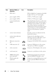
...to the system Dedicated management port for the optional iDRAC6 Enterprise card Connects an external SD memory card for attaching a system indicator extension cable that is pushed again. Item Indicator, Button, or Icon Connector 4 PCIe slot 4 5 power supply 1 (PS1) 6 power supply 2 (PS2) 7 system identification...(4) 11 USB connectors (2) 12 video connector 13 serial connector 14 iDRAC6 Enterprise port (optional) 15 VFlash media slot (optional) Description PCIe x8-link Gen 2 expansion slot (fullheight, 24.13-cm [9.5-in] length) 870-W or 570-W power supply 870-W or 570-W power supply...
...to the system Dedicated management port for the optional iDRAC6 Enterprise card Connects an external SD memory card for attaching a system indicator extension cable that is pushed again. Item Indicator, Button, or Icon Connector 4 PCIe slot 4 5 power supply 1 (PS1) 6 power supply 2 (PS2) 7 system identification...(4) 11 USB connectors (2) 12 video connector 13 serial connector 14 iDRAC6 Enterprise port (optional) 15 VFlash media slot (optional) Description PCIe x8-link Gen 2 expansion slot (fullheight, 24.13-cm [9.5-in] length) 870-W or 570-W power supply 870-W or 570-W power supply...
Hardware Manual
Page 35
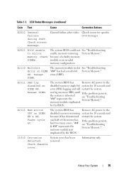
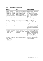
... If the problem persists, the system is rebooted. Check chassis cover. Check screen for 10 seconds and because it has determined restart the system. The memory module in slot See "Troubleshooting "##" has had too many errors. error (MBE). The system BIOS has Remove AC power to mirror...
... If the problem persists, the system is rebooted. Check chassis cover. Check screen for 10 seconds and because it has determined restart the system. The memory module in slot See "Troubleshooting "##" has had too many errors. error (MBE). The system BIOS has Remove AC power to mirror...
Hardware Manual
Page 40
... jumper is installed on system board NVRAM_CLR jumper is Move the NVRAM_CLR installed in the system. See "Processors." System halted CPUs with no memory. Restart the system and re-enter the BIOS settings. CPU x installed with different power rating detected! jumper to minimum frequency. See "... and logical processors, and power rating. position (pins 3 and 5). Table 1-2. messages for required but not installed in the processor. memory slots. CPUs with different cache sizes detected. Ensure that all processors been installed in the clear setting.
... jumper is installed on system board NVRAM_CLR jumper is Move the NVRAM_CLR installed in the system. See "Processors." System halted CPUs with no memory. Restart the system and re-enter the BIOS settings. CPU x installed with different power rating detected! jumper to minimum frequency. See "... and logical processors, and power rating. position (pins 3 and 5). Table 1-2. messages for required but not installed in the processor. memory slots. CPUs with different cache sizes detected. Ensure that all processors been installed in the clear setting.
Hardware Manual
Page 48
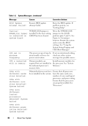
... the Time and Date settings. The following DIMMs should match in size, number of "General Memory Module ranks, or number of data Installation Guidelines." The following DIMMs should match in size: x,x,... please run settings...memory Ensure that the memory configuration. Table 1-2. Thermal sensor A memory module without a Replace the memory module. Time-of -day clock stopped Faulty battery or faulty chip. lanes. The following DIMMs should match in size and rank count: x,x,... See "Using the System Setup Program and UEFI Boot Manager." the specified memory slot...
... the Time and Date settings. The following DIMMs should match in size, number of "General Memory Module ranks, or number of data Installation Guidelines." The following DIMMs should match in size: x,x,... please run settings...memory Ensure that the memory configuration. Table 1-2. Thermal sensor A memory module without a Replace the memory module. Time-of -day clock stopped Faulty battery or faulty chip. lanes. The following DIMMs should match in size and rank count: x,x,... See "Using the System Setup Program and UEFI Boot Manager." the specified memory slot...

Hardware Manual
Page 50
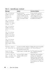
...dell.com. Reseat the memory modules. See "Troubleshooting System Memory." See "Processors." Ensure that the memory modules are installed in the system firmware or has been lost due to system board replacement. See "General Memory Module Installation Guidelines." Invalid memory... memory. If the problem persists, see "Getting Help." Unsupported memory configuration. Memory modules are installed in the specified slots. DIMM mismatch across slots detected: x,x,... See "General Memory Module Installation Guidelines." 50 About Your System Table 1-2. Ensure that the memory ...
...dell.com. Reseat the memory modules. See "Troubleshooting System Memory." See "Processors." Ensure that the memory modules are installed in the system firmware or has been lost due to system board replacement. See "General Memory Module Installation Guidelines." Invalid memory... memory. If the problem persists, see "Getting Help." Unsupported memory configuration. Memory modules are installed in the specified slots. DIMM mismatch across slots detected: x,x,... See "General Memory Module Installation Guidelines." 50 About Your System Table 1-2. Ensure that the memory ...
Hardware Manual
Page 51
... installed. See "Control Panel Assembly." code update loaded for detected. System Messages (continued) Message Causes Corrective Actions Unused memory The memory configuration is Reconfigure the memory for processor n Update the BIOS firmware. reboot. No micro Micro code update failed. ECC modes: x,x,x Warning: ... caused and caused the system to Optimized in the when in the Advanced ECC Memory Advanced ECC Memory following slot Mode. section in "Troubleshooting Your System" for any faulty components specified in the Mode, or change the memory are not available specified...
... installed. See "Control Panel Assembly." code update loaded for detected. System Messages (continued) Message Causes Corrective Actions Unused memory The memory configuration is Reconfigure the memory for processor n Update the BIOS firmware. reboot. No micro Micro code update failed. ECC modes: x,x,x Warning: ... caused and caused the system to Optimized in the when in the Advanced ECC Memory Advanced ECC Memory following slot Mode. section in "Troubleshooting Your System" for any faulty components specified in the Mode, or change the memory are not available specified...
Hardware Manual
Page 76
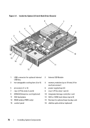
...USB key 3 hot-swappable cooling fans (4 or 5) 5 processors (1 or 2) 7 riser 2 (PCIe slots 3 and 4) 9 iDRAC6 Enterprise card (optional) 11 SAS backplane 13 RAID battery (PERC only) 15 control panel 2 Internal SD Module 4 memory modules (up to 18 total, 9 for each processor) 6 power supply bays (2) 8 riser 1 (...PCIe slots 1 and 2) 10 integrated storage controller card 12 SAS or SATA hard drives (up to 8) 14 flex...
...USB key 3 hot-swappable cooling fans (4 or 5) 5 processors (1 or 2) 7 riser 2 (PCIe slots 3 and 4) 9 iDRAC6 Enterprise card (optional) 11 SAS backplane 13 RAID battery (PERC only) 15 control panel 2 Internal SD Module 4 memory modules (up to 18 total, 9 for each processor) 6 power supply bays (2) 8 riser 1 (...PCIe slots 1 and 2) 10 integrated storage controller card 12 SAS or SATA hard drives (up to 8) 14 flex...
Hardware Manual
Page 91
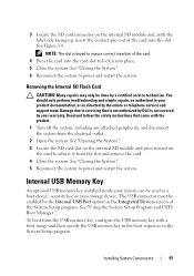
...instructions that is not authorized by Dell is keyed to ensure correct insertion of the card into place. 5 Close the system. NOTE: The slot is not covered by the online or telephone service and support team. See Figure 3-8. Internal USB Memory Key An optional USB memory key installed inside your warranty. ...pin end of the card. 4 Press the card into the card slot to lock it from the electrical outlet. 2 Open the system. Damage due to release it into the slot. To boot from the USB memory key, configure the USB memory key with the product. 1 Turn off the system, including any ...
...instructions that is not authorized by Dell is keyed to ensure correct insertion of the card into place. 5 Close the system. NOTE: The slot is not covered by the online or telephone service and support team. See Figure 3-8. Internal USB Memory Key An optional USB memory key installed inside your warranty. ...pin end of the card. 4 Press the card into the card slot to lock it from the electrical outlet. 2 Open the system. Damage due to release it into the slot. To boot from the USB memory key, configure the USB memory key with the product. 1 Turn off the system, including any ...
Hardware Manual
Page 129
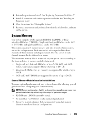
... following general guidelines when configuring your system and peripherals to 96 GB. • 1-GB and 2-GB UDIMMs are unused, all expansion cards in the expansion-card slots. Installing System Components 129 4 Reinstall expansion-card riser 2. See "Closing the System." 7 Reconnect your system memory. System Memory Your system supports DDR3 registered DIMMs (RDIMMs) or ECC unbuffered DIMMs...
... following general guidelines when configuring your system and peripherals to 96 GB. • 1-GB and 2-GB UDIMMs are unused, all expansion cards in the expansion-card slots. Installing System Components 129 4 Reinstall expansion-card riser 2. See "Closing the System." 7 Reconnect your system memory. System Memory Your system supports DDR3 registered DIMMs (RDIMMs) or ECC unbuffered DIMMs...

Hardware Manual
Page 131
... be identical in size, speed, and technology in corresponding slots. A minimal single-channel configuration of any configuration. The samples show mixed or quad-rank memory-module configurations, nor do they address the memory speed considerations of one 128-bit channel. Advanced ECC (...to form one 1-GB memory module per processor is also supported in this mode. Table 3-2 and Table 3-3 show sample memory configurations that follow the appropriate memory guidelines stated in this section. and x8based memory modules. This mode permits a larger total memory capacity but does not...
... be identical in size, speed, and technology in corresponding slots. A minimal single-channel configuration of any configuration. The samples show mixed or quad-rank memory-module configurations, nor do they address the memory speed considerations of one 128-bit channel. Advanced ECC (...to form one 1-GB memory module per processor is also supported in this mode. Table 3-2 and Table 3-3 show sample memory configurations that follow the appropriate memory guidelines stated in this section. and x8based memory modules. This mode permits a larger total memory capacity but does not...

Hardware Manual
Page 150
... system board and remove the label placard that all of the system. See "Removing Memory Modules" and "Installing Memory Modules." 5 Install the new system board: a Angle the system board as you lower it into the retention slots on the new board. b Maneuver the system board so that is inserted in the... memory module socket. 2 Remove the labels from the placard and affix them to the same locations on the system ...
... system board and remove the label placard that all of the system. See "Removing Memory Modules" and "Installing Memory Modules." 5 Install the new system board: a Angle the system board as you lower it into the retention slots on the new board. b Maneuver the system board so that is inserted in the... memory module socket. 2 Remove the labels from the placard and affix them to the same locations on the system ...
Hardware Manual
Page 181
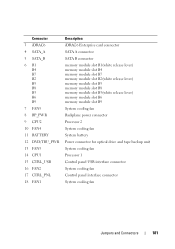
... CTRL_PNL 18 FAN1 Description iDRAC6 Enterprise card connector SATA A connector SATA B connector memory module slot B1(white release lever) memory module slot B4 memory module slot B7 memory module slot B2(white release lever) memory module slot B5 memory module slot B8 memory module slot B3(white release lever) memory module slot B6 memory module slot B9 System cooling fan Backplane power connector Processor 2 System cooling fan System...
... CTRL_PNL 18 FAN1 Description iDRAC6 Enterprise card connector SATA A connector SATA B connector memory module slot B1(white release lever) memory module slot B4 memory module slot B7 memory module slot B2(white release lever) memory module slot B5 memory module slot B8 memory module slot B3(white release lever) memory module slot B6 memory module slot B9 System cooling fan Backplane power connector Processor 2 System cooling fan System...

Hardware Manual
Page 182
SAS Backplane Board for PS1 NIC hardware key SAS Backplane Board Connectors Figure 6-3. Connector 19 A1 A4 A7 A2 A5 A8 A3 A6 A9 20 PWR2 21 PWR1 22 ISCSI_KEY Description memory module slot A1(white release lever) memory module slot A4 memory module slot A7 memory module slot A2(white release lever) memory module slot A5 memory module slot A8 memory module slot A3(white release lever) memory module slot A6 memory module slot A9 Power supply connector for PS2 Power supply connector for 2.5-Inch Hard Drives 1 front 5 4 2 3 back 182 Jumpers and Connectors
SAS Backplane Board for PS1 NIC hardware key SAS Backplane Board Connectors Figure 6-3. Connector 19 A1 A4 A7 A2 A5 A8 A3 A6 A9 20 PWR2 21 PWR1 22 ISCSI_KEY Description memory module slot A1(white release lever) memory module slot A4 memory module slot A7 memory module slot A2(white release lever) memory module slot A5 memory module slot A8 memory module slot A3(white release lever) memory module slot A6 memory module slot A9 Power supply connector for PS2 Power supply connector for 2.5-Inch Hard Drives 1 front 5 4 2 3 back 182 Jumpers and Connectors

Hardware Manual
Page 198
...mice and keyboards. UDIMM - USB - A USB connector provides a single connection point for example. USB memory key - The logical circuitry that plugs into an expansion slot. Video resolution (800 x 600, for the devices. TCP/IP - Unified Extensible Firmware Interface. A ...battery-powered unit that offloads network processing to your system's video capabilities. USB devices can display (with the monitor) your system's RAM. See memory key. ...
...mice and keyboards. UDIMM - USB - A USB connector provides a single connection point for example. USB memory key - The logical circuitry that plugs into an expansion slot. Video resolution (800 x 600, for the devices. TCP/IP - Unified Extensible Firmware Interface. A ...battery-powered unit that offloads network processing to your system's video capabilities. USB devices can display (with the monitor) your system's RAM. See memory key. ...

Hardware Manual
Page 206
...cabling for six 3.5-in HDD chassis, 116 installing, 112 removing, 112 troubleshooting, 167 support contacting Dell, 189 system board connectors, 180 installing, 150 jumpers, 177 removing, 148 system cooling troubleshooting, 159... management options, 64 integrated devices options, 62 keystroke to enter, 56 main screen, 57 memory settings, 59 PCI IRQ assignments, 63 power management options, 65 processor settings, 60 SATA settings...drives, 182 3.5-inch hard drives (4 slots), 183 3.5-inch hard drives (6 slots), 184 connectors, 182 installing, 147 removing, 146 SAS controller See storage controller.
...cabling for six 3.5-in HDD chassis, 116 installing, 112 removing, 112 troubleshooting, 167 support contacting Dell, 189 system board connectors, 180 installing, 150 jumpers, 177 removing, 148 system cooling troubleshooting, 159... management options, 64 integrated devices options, 62 keystroke to enter, 56 main screen, 57 memory settings, 59 PCI IRQ assignments, 63 power management options, 65 processor settings, 60 SATA settings...drives, 182 3.5-inch hard drives (4 slots), 183 3.5-inch hard drives (6 slots), 184 connectors, 182 installing, 147 removing, 146 SAS controller See storage controller.
Technical Guide
Page 4
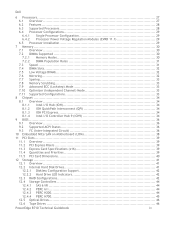
Dell 6 Processors ...27 6.1 Overview 27 6.2 Features 28 6.3 Supported Processors 28 6.4 Processor Configurations 29 6.4.1 Single Processor Configuration 29 6.4.2 Processor Power Voltage Regulation Modules (EVRD 11.1 29 6.5 Processor Installation 29 7 Memory ...30 7.1 Overview 30 7.2 DIMMs Supported 30 7.2.1 Memory Modes 30 7.2.2 DIMM Population Rules 31 7.3 Speed ...31 7.4 DIMM Slots 32 7.5 Low Voltage DIMMs 32... 44 12.4.2 PERC 6/i 44 12.4.3 PERC H200 44 12.4.4 PERC H700 45 12.5 Optical Drives 46 12.6 Tape Drives 46 PowerEdge R710 Technical Guidebook iv
Dell 6 Processors ...27 6.1 Overview 27 6.2 Features 28 6.3 Supported Processors 28 6.4 Processor Configurations 29 6.4.1 Single Processor Configuration 29 6.4.2 Processor Power Voltage Regulation Modules (EVRD 11.1 29 6.5 Processor Installation 29 7 Memory ...30 7.1 Overview 30 7.2 DIMMs Supported 30 7.2.1 Memory Modes 30 7.2.2 DIMM Population Rules 31 7.3 Speed ...31 7.4 DIMM Slots 32 7.5 Low Voltage DIMMs 32... 44 12.4.2 PERC 6/i 44 12.4.3 PERC H200 44 12.4.4 PERC H700 45 12.5 Optical Drives 46 12.6 Tape Drives 46 PowerEdge R710 Technical Guidebook iv
Technical Guide
Page 7
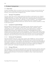
...PowerEdge R710 is designed for better reliability. 1.1.3 Enhanced Virtualization Featuring embedded hypervisors, large memory capacity with Energy Smart technologies such as right-sized efficient power supply units, improved system-level design efficiency, and policy-driven power and thermal management. The PowerEdge R710...a few mouse clicks. 1.1.4 Energy Efficient The PowerEdge R710 reduces power consumption while increasing performance capacity with 18 DIMM slots, and four integrated network connections, the Dell PowerEdge R710 delivers better overall system performance and greater virtual ...
...PowerEdge R710 is designed for better reliability. 1.1.3 Enhanced Virtualization Featuring embedded hypervisors, large memory capacity with Energy Smart technologies such as right-sized efficient power supply units, improved system-level design efficiency, and policy-driven power and thermal management. The PowerEdge R710...a few mouse clicks. 1.1.4 Energy Efficient The PowerEdge R710 reduces power consumption while increasing performance capacity with 18 DIMM slots, and four integrated network connections, the Dell PowerEdge R710 delivers better overall system performance and greater virtual ...
Technical Guide
Page 9
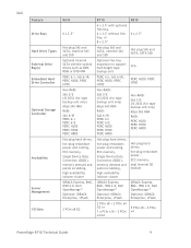
...PERC H700 PERC H800 Hot-plug hard drives, hot-plug redundant power and cooling, ECC memory, Single Device Data Correction (SDDC), memory demand and patrol scrubbing, high-availability failover cluster Hot-plug hard drives, hot-plug redundant power... x4 G2 or 1 x PCIe x16 + 2 PCIe x4 G2 5 PCIe x8 + 2 PCIe x4 PowerEdge R710 Technical Guide 9 Dell Feature Drive Bays Hard Drive Types External Drive Bay(s) Embedded Hard Drive Controller Optional Storage Controller Availability Server Management I/O Slots R610 R710 R810 6 x 2.5‖ 4 x 3.5" with optional flex bay, 6 x 3.5" without flex bay, ...
...PERC H700 PERC H800 Hot-plug hard drives, hot-plug redundant power and cooling, ECC memory, Single Device Data Correction (SDDC), memory demand and patrol scrubbing, high-availability failover cluster Hot-plug hard drives, hot-plug redundant power... x4 G2 or 1 x PCIe x16 + 2 PCIe x4 G2 5 PCIe x8 + 2 PCIe x4 PowerEdge R710 Technical Guide 9 Dell Feature Drive Bays Hard Drive Types External Drive Bay(s) Embedded Hard Drive Controller Optional Storage Controller Availability Server Management I/O Slots R610 R710 R810 6 x 2.5‖ 4 x 3.5" with optional flex bay, 6 x 3.5" without flex bay, ...

Technical Guide
Page 31
... is enabled, identical DIMMs must be installed in the same slots across both channels. Figure 10. o This mode provides improved RAS features (SDDC support for memory mirroring. The R710 memory system supports up to both channels and reads alternate between the two channels). Dell The first two channels per processor populated o This...
... is enabled, identical DIMMs must be installed in the same slots across both channels. Figure 10. o This mode provides improved RAS features (SDDC support for memory mirroring. The R710 memory system supports up to both channels and reads alternate between the two channels). Dell The first two channels per processor populated o This...

Technical Guide
Page 32
...does not support low voltage operation. However, due to the processor (memory not installed in each channel depends on the processor populated. Contact your Dell Sales Representative or visit Dell.com for the PowerEdge R710. If the system detects a mixture of standard and LV DIMMs, the... supports operating DIMMs at 1.5V. The DDR3L standard is not supported at the speed of the slowest installed memory module(s). 7.4 DIMM Slots The PowerEdge R710 has 18 DIMM slots for ease of the LV type. Mirroring must be of installation. Therefore, DDR3L DIMMs can operate at 1....
...does not support low voltage operation. However, due to the processor (memory not installed in each channel depends on the processor populated. Contact your Dell Sales Representative or visit Dell.com for the PowerEdge R710. If the system detects a mixture of standard and LV DIMMs, the... supports operating DIMMs at 1.5V. The DDR3L standard is not supported at the speed of the slowest installed memory module(s). 7.4 DIMM Slots The PowerEdge R710 has 18 DIMM slots for ease of the LV type. Mirroring must be of installation. Therefore, DDR3L DIMMs can operate at 1....


