
Hardware Manual
Page 6
...Internal USB Memory Key 91 Internal USB Cable 93 Removing the Internal USB Cable 93 Installing the Internal USB Cable 93 Integrated Dell Remote Access Controller 6 (iDRAC6) Enterprise Card (Optional 94 Installing an iDRAC6 Enterprise Card 94 Removing an iDRAC6 Enterprise Card ...Key 97 Cooling Shroud 98 Removing the Cooling Shroud 99 Installing the Cooling Shroud 100 Cooling Fans 100 Removing a Cooling Fan 100 Replacing a Cooling Fan 101 Removing the Fan Bracket 102 Replacing the Fan Bracket 103 Optical Drive 103 Removing the Optical Drive 104 Installing the Optical Drive 104 ...
...Internal USB Memory Key 91 Internal USB Cable 93 Removing the Internal USB Cable 93 Installing the Internal USB Cable 93 Integrated Dell Remote Access Controller 6 (iDRAC6) Enterprise Card (Optional 94 Installing an iDRAC6 Enterprise Card 94 Removing an iDRAC6 Enterprise Card ...Key 97 Cooling Shroud 98 Removing the Cooling Shroud 99 Installing the Cooling Shroud 100 Cooling Fans 100 Removing a Cooling Fan 100 Replacing a Cooling Fan 101 Removing the Fan Bracket 102 Replacing the Fan Bracket 103 Optical Drive 103 Removing the Optical Drive 104 Installing the Optical Drive 104 ...
Hardware Manual
Page 53
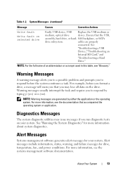
... drive, a message will warn you that the USB, assembly, hard drive, or hard- Alert Messages Systems management software generates alert messages for drive, temperature, fan, and power conditions. NOTE: Warning messages are properly connected. Alert messages include information, status, warning, and failure messages for your system. Table 1-2. See "...the operating system. System Messages (continued) Message Causes Corrective Actions Write fault Write fault on selected drive Faulty USB device, USB Replace the USB medium or medium, optical drive device.
... drive, a message will warn you that the USB, assembly, hard drive, or hard- Alert Messages Systems management software generates alert messages for drive, temperature, fan, and power conditions. NOTE: Warning messages are properly connected. Alert messages include information, status, warning, and failure messages for your system. Table 1-2. See "...the operating system. System Messages (continued) Message Causes Corrective Actions Write fault Write fault on selected drive Faulty USB device, USB Replace the USB medium or medium, optical drive device.
Hardware Manual
Page 93
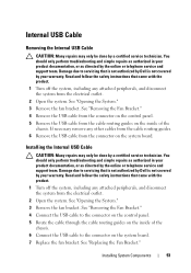
... the cable routing guides on the control panel. 5 Remove the USB cable from the electrical outlet. 2 Open the system. See "Replacing the Fan Bracket." Installing the Internal USB Cable CAUTION: Many repairs may only be done by a certified service technician. Damage due to the connector...remove any attached peripherals, and disconnect the system from the connector on the system board. 7 Replace the fan bracket. Read and follow the safety instructions that is not authorized by Dell is not covered by your product documentation, or as directed by the online or telephone service...
... the cable routing guides on the control panel. 5 Remove the USB cable from the electrical outlet. 2 Open the system. See "Replacing the Fan Bracket." Installing the Internal USB Cable CAUTION: Many repairs may only be done by a certified service technician. Damage due to the connector...remove any attached peripherals, and disconnect the system from the connector on the system board. 7 Replace the fan bracket. Read and follow the safety instructions that is not authorized by Dell is not covered by your product documentation, or as directed by the online or telephone service...
Hardware Manual
Page 100
... directed by the system's management software, allowing you to easily identify and replace the proper fan. CAUTION: The cooling fans are hot-swappable. Fan 5 can be done by Dell is installed in FAN5 in a single-processor configuration, the fan will not appear in the fan 5 bay. Damage due to maintain proper cooling while the system is on...
... directed by the system's management software, allowing you to easily identify and replace the proper fan. CAUTION: The cooling fans are hot-swappable. Fan 5 can be done by Dell is installed in FAN5 in a single-processor configuration, the fan will not appear in the fan 5 bay. Damage due to maintain proper cooling while the system is on...
Hardware Manual
Page 101
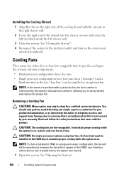
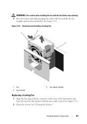
Removing and Installing a Cooling Fan 2 1 3 1 fan 3 fan bracket 2 fan release handle Replacing a Cooling Fan 1 Align the fan plug with the connector at the base of the fan bracket and lower the fan into the bracket until the fan blades stop spinning. 2 Press the release tab while grasping the ends of the fan and lift the fan straight up from the fan bracket. Figure 3-13. See Figure 3-13. See "Closing the System." See Figure 3-13. 2 Close the system. WARNING: Use caution when handling the fan until the fan is fully seated. Installing System Components 101
Removing and Installing a Cooling Fan 2 1 3 1 fan 3 fan bracket 2 fan release handle Replacing a Cooling Fan 1 Align the fan plug with the connector at the base of the fan bracket and lower the fan into the bracket until the fan blades stop spinning. 2 Press the release tab while grasping the ends of the fan and lift the fan straight up from the fan bracket. Figure 3-13. See Figure 3-13. See "Closing the System." See Figure 3-13. 2 Close the system. WARNING: Use caution when handling the fan until the fan is fully seated. Installing System Components 101
Hardware Manual
Page 103
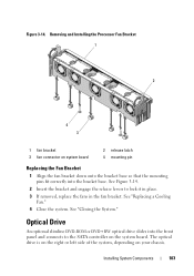
Removing and Installing the Processor Fan Bracket 1 2 4 3 1 fan bracket 3 fan connector on your chassis. See "Replacing a Cooling Fan." 4 Close the system. Optical Drive An optional slimline DVD-ROM or DVD+RW optical drive slides into the bracket base. See Figure 3-14. 2 Insert the ... system board. The optical drive is on the right or left side of the system, depending on system board 2 release latch 4 mounting pin Replacing the Fan Bracket 1 Align the fan bracket down onto the bracket base so that the mounting pins fit correctly into the front panel and connects to lock it in...
Removing and Installing the Processor Fan Bracket 1 2 4 3 1 fan bracket 3 fan connector on your chassis. See "Replacing a Cooling Fan." 4 Close the system. Optical Drive An optional slimline DVD-ROM or DVD+RW optical drive slides into the bracket base. See Figure 3-14. 2 Insert the ... system board. The optical drive is on the right or left side of the system, depending on system board 2 release latch 4 mounting pin Replacing the Fan Bracket 1 Align the fan bracket down onto the bracket base so that the mounting pins fit correctly into the front panel and connects to lock it in...
Hardware Manual
Page 105
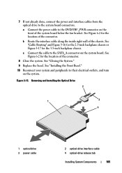
...location of the connector. 8 Close the system. c Connect the cable to their electrical outlets, and turn on the system board. See "Closing the System." 9 Replace the bezel. See Figure 6-2 for the 3.5-inch backplane chassis. Removing and Installing the Optical Drive 2 3 1 4 1 optical drive 3 power cable 2 optical-... 3-17 for the location of the connector. b Route the interface cable along the inside right wall of the system board below the fan bracket. See "Installing the Front Bezel." 10 Reconnect your system and peripherals to the SATA_A connector on the system. Figure 3-15. ...
...location of the connector. 8 Close the system. c Connect the cable to their electrical outlets, and turn on the system board. See "Closing the System." 9 Replace the bezel. See Figure 6-2 for the 3.5-inch backplane chassis. Removing and Installing the Optical Drive 2 3 1 4 1 optical drive 3 power cable 2 optical-... 3-17 for the location of the connector. b Route the interface cable along the inside right wall of the system board below the fan bracket. See "Installing the Front Bezel." 10 Reconnect your system and peripherals to the SATA_A connector on the system. Figure 3-15. ...
Hardware Manual
Page 119
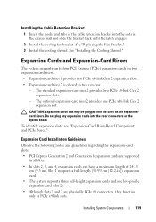
...2 and Generation 1 expansion cards are physically PCIe x8 connectors, they function only as PCIe x4-link slots. Installing System Components 119 See "Replacing the Fan Bracket." 3 Install the cooling shroud. See "Installing the Cooling Shroud." The optional expansion-card riser 2 provides one low-profile expansion card ...-length (30.99-cm [12.2-in the chassis wall and slide the bracket back until the latch engages. 2 Install the cooling fan bracket. Expansion Cards and Expansion-Card Risers The system supports up to four PCI Express (PCIe) expansion cards on the expansioncard risers....
...2 and Generation 1 expansion cards are physically PCIe x8 connectors, they function only as PCIe x4-link slots. Installing System Components 119 See "Replacing the Fan Bracket." 3 Install the cooling shroud. See "Installing the Cooling Shroud." The optional expansion-card riser 2 provides one low-profile expansion card ...-length (30.99-cm [12.2-in the chassis wall and slide the bracket back until the latch engages. 2 Install the cooling fan bracket. Expansion Cards and Expansion-Card Risers The system supports up to four PCI Express (PCIe) expansion cards on the expansioncard risers....
Hardware Manual
Page 141
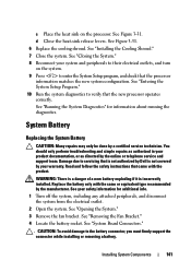
...manufacturer. WARNING: There is a danger of a new battery exploding if it is not covered by Dell is incorrectly installed. See "Opening the System." 3 Remove the fan bracket. See "Removing the Fan Bracket." 4 Locate the battery socket. See "Closing the System." 8 Reconnect your product documentation, ...the system. Damage due to the battery connector, you must firmly support the connector while installing or removing a battery. System Battery Replacing the System Battery CAUTION: Many repairs may only be done by the online or telephone service and support team. See "Running ...
...manufacturer. WARNING: There is a danger of a new battery exploding if it is not covered by Dell is incorrectly installed. See "Opening the System." 3 Remove the fan bracket. See "Removing the Fan Bracket." 4 Locate the battery socket. See "Closing the System." 8 Reconnect your product documentation, ...the system. Damage due to the battery connector, you must firmly support the connector while installing or removing a battery. System Battery Replacing the System Battery CAUTION: Many repairs may only be done by the online or telephone service and support team. See "Running ...
Hardware Manual
Page 142
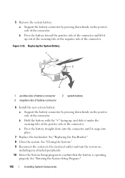
... side of the connector. See "Entering the System Setup Program." 142 Installing System Components c Press the battery straight down into place. 7 Replace the fan bracket. 5 Remove the system battery. b Press the battery toward the positive side of the connector and lift it up , and slide ...connector until it under the securing tabs at the negative side of battery connector 2 system battery 6 Install the new system battery. See "Replacing the Fan Bracket." 8 Close the system. See "Closing the System." 9 Reconnect the system to the electrical outlet and turn the system on the...
... side of the connector. See "Entering the System Setup Program." 142 Installing System Components c Press the battery straight down into place. 7 Replace the fan bracket. 5 Remove the system battery. b Press the battery toward the positive side of the connector and lift it up , and slide ...connector until it under the securing tabs at the negative side of battery connector 2 system battery 6 Install the new system battery. See "Replacing the Fan Bracket." 8 Close the system. See "Closing the System." 9 Reconnect the system to the electrical outlet and turn the system on the...
Hardware Manual
Page 149
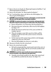
...drives. See Figure 3-36. 7 Remove the two riser boards. See "Removing Expansion-Card Riser 1" and "Removing Expansion-Card Riser 2." 8 Remove the fan bracket. Installing System Components 149 a Remove all cables from the system board. 11 Remove the system board assembly: a Pull up the spring-loaded blue retention...system before removal to ensure that you must note the number of the system to the drives and backplane, you can replace them before removing the backplane. See "Removing the Fan Bracket." 9 Six 3.5-inch hard-drive chassis only: Remove the SAS backplane.
...drives. See Figure 3-36. 7 Remove the two riser boards. See "Removing Expansion-Card Riser 1" and "Removing Expansion-Card Riser 2." 8 Remove the fan bracket. Installing System Components 149 a Remove all cables from the system board. 11 Remove the system board assembly: a Pull up the spring-loaded blue retention...system before removal to ensure that you must note the number of the system to the drives and backplane, you can replace them before removing the backplane. See "Removing the Fan Bracket." 9 Six 3.5-inch hard-drive chassis only: Remove the SAS backplane.
Hardware Manual
Page 151
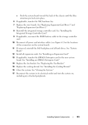
...system board). 11 If removed, reinstall the SAS backplane and all expansion cards. See "Installing an iDRAC6 Enterprise Card." 14 Replace the fan bracket. c Push the system board toward the back of the connectors on , including any attached peripherals. See "Closing the ...System." 17 Reconnect the system to the new system board. See "Replacing Expansion-Card Riser 1" and "Replacing Expansion-Card Riser 2." 8 Reinstall the integrated storage controller card. See "System Board." 12 Install all hard drives. See "Replacing the Fan Bracket." 15 Replace the cooling shroud.
...system board). 11 If removed, reinstall the SAS backplane and all expansion cards. See "Installing an iDRAC6 Enterprise Card." 14 Replace the fan bracket. c Push the system board toward the back of the connectors on , including any attached peripherals. See "Closing the ...System." 17 Reconnect the system to the new system board. See "Replacing Expansion-Card Riser 1" and "Replacing Expansion-Card Riser 2." 8 Reinstall the integrated storage controller card. See "System Board." 12 Install all hard drives. See "Replacing the Fan Bracket." 15 Replace the cooling shroud.
Hardware Manual
Page 160
... by your product documentation, or as directed by Dell is removed or has failed. Troubleshooting a Fan CAUTION: Many repairs may only be done by Dell is too high. See "Opening the System." If the replacement fan does not operate, see "Getting Help." See "Removing a Cooling Fan" and "Replacing a Cooling Fan." You should only perform troubleshooting and simple repairs...
... by your product documentation, or as directed by Dell is removed or has failed. Troubleshooting a Fan CAUTION: Many repairs may only be done by Dell is too high. See "Opening the System." If the replacement fan does not operate, see "Getting Help." See "Removing a Cooling Fan" and "Replacing a Cooling Fan." You should only perform troubleshooting and simple repairs...
Hardware Manual
Page 201
... Advanced ECC memory mode, 131 B back panel features, 19 backplane See SAS backplane. battery (RAID) installing, 116 removing, 116 battery (system) replacing, 141 troubleshooting, 158 BIOS boot mode, 55 blank hard drive, 81 power supply, 88 boot mode, 55 C cable retention bracket installing, 119 ... 185 expansion-card riser 2, 186-187 NIC, 20 SAS backplane board, 182 serial, 20 system board, 180 USB, 12 video, 12 contacting Dell, 189 control panel assembly features, 12 LCD panel features, 15 control panel board installing, 145 removing, 144 control panel display module installing, 143 removing...
... Advanced ECC memory mode, 131 B back panel features, 19 backplane See SAS backplane. battery (RAID) installing, 116 removing, 116 battery (system) replacing, 141 troubleshooting, 158 BIOS boot mode, 55 blank hard drive, 81 power supply, 88 boot mode, 55 C cable retention bracket installing, 119 ... 185 expansion-card riser 2, 186-187 NIC, 20 SAS backplane board, 182 serial, 20 system board, 180 USB, 12 video, 12 contacting Dell, 189 control panel assembly features, 12 LCD panel features, 15 control panel board installing, 145 removing, 144 control panel display module installing, 143 removing...
Hardware Manual
Page 202
... closing, 79 opening, 79 D damaged systems troubleshooting, 157 Dell contacting, 189 diagnostics testing options, 174 using Dell PowerEdge Diagnostics, 173 DIMMs See memory modules (DIMMs). E error ...messages, 56 expansion cards See PCIe expansion cards. expansion-card riser 1 connectors, 185 installing, 124 removing, 123 expansion-card riser 2 connectors, 186-187 installing, 126 installing into expansion-card bracket, 128 removing, 125 removing from expansion-card bracket, 127 F fan removing, 100 replacing, 101 fan...
... closing, 79 opening, 79 D damaged systems troubleshooting, 157 Dell contacting, 189 diagnostics testing options, 174 using Dell PowerEdge Diagnostics, 173 DIMMs See memory modules (DIMMs). E error ...messages, 56 expansion cards See PCIe expansion cards. expansion-card riser 1 connectors, 185 installing, 124 removing, 123 expansion-card riser 2 connectors, 186-187 installing, 126 installing into expansion-card bracket, 128 removing, 125 removing from expansion-card bracket, 127 F fan removing, 100 replacing, 101 fan...
Hardware Manual
Page 203
..., 84 installing, 83 mixed configurations, 81 removing, 82 troubleshooting, 166 heat sink, 138 hot-swap cooling fans, 100 hard drives, 80 power supplies, 86 I iDRAC Configuration Utility, 73 iDRAC6 Enterprise card installing, 94...indicators back panel, 19 front-panel, 12 NIC, 22 power, 12, 21 information tag removing, 78 replacing, 78 installing cable retention bracket, 119 control panel board, 145 control panel display module, 143 cooling shroud... unit, 107 VFlash SD card, 96 Integrated Dell Remote Access Controller See iDRAC6 Enterprise card. integrated storage controller See storage controller.
..., 84 installing, 83 mixed configurations, 81 removing, 82 troubleshooting, 166 heat sink, 138 hot-swap cooling fans, 100 hard drives, 80 power supplies, 86 I iDRAC Configuration Utility, 73 iDRAC6 Enterprise card installing, 94...indicators back panel, 19 front-panel, 12 NIC, 22 power, 12, 21 information tag removing, 78 replacing, 78 installing cable retention bracket, 119 control panel board, 145 control panel display module, 143 cooling shroud... unit, 107 VFlash SD card, 96 Integrated Dell Remote Access Controller See iDRAC6 Enterprise card. integrated storage controller See storage controller.
Hardware Manual
Page 205
... 122 riser boards, 185 troubleshooting, 168 POST accessing system features, 11 power indicators, 12, 21 power supplies indicators, 21 removing, 86 replacing, 87 troubleshooting, 158 power supply blank, 88 processor installing, 140 removing, 137 troubleshooting, 170 upgrades, 137 PSU See power supply. R...2 from bracket, 127 SAS backplane board, 146 SD card, 91 system board, 148 tape backup unit, 110 replacing cooling fan, 101 expansion-card riser 1, 124 expansion-card riser 2, 126 fan brackets, 103 information tag, 78 power supply, 87 system battery, 141 S safety, 153 SAS backplane board Index ...
... 122 riser boards, 185 troubleshooting, 168 POST accessing system features, 11 power indicators, 12, 21 power supplies indicators, 21 removing, 86 replacing, 87 troubleshooting, 158 power supply blank, 88 processor installing, 140 removing, 137 troubleshooting, 170 upgrades, 137 PSU See power supply. R...2 from bracket, 127 SAS backplane board, 146 SD card, 91 system board, 148 tape backup unit, 110 replacing cooling fan, 101 expansion-card riser 1, 124 expansion-card riser 2, 126 fan brackets, 103 information tag, 78 power supply, 87 system battery, 141 S safety, 153 SAS backplane board Index ...
Technical Guide
Page 3
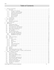
...-Inspired Design 7 1.1.3 Enhanced Virtualization 7 1.1.4 Energy Efficient 7 1.1.5 Easy to Manage 8 1.1.6 Dell Services 8 1.2 Comparison 8 2 Key Technologies 11 2.1 Overview 11 2.2 Detailed Information 11 3 ...and Cable Management 18 4.8.1 ReadyRails Sliding Rails 18 4.8.2 ReadyRails Static Rails 19 4.9 Fans ...19 4.10 LCD Control Panel 19 4.11 Security 20 4.11.1 Cover Latch ....7 Secure Mode 21 4.12 USB Key 21 4.13 Battery 21 4.14 Field Replaceable Units (FRU 21 4.15 User Accessible Jumpers, Sockets, and Connectors 21 5 ...PowerEdge R710 Technical Guidebook iii
...-Inspired Design 7 1.1.3 Enhanced Virtualization 7 1.1.4 Energy Efficient 7 1.1.5 Easy to Manage 8 1.1.6 Dell Services 8 1.2 Comparison 8 2 Key Technologies 11 2.1 Overview 11 2.2 Detailed Information 11 3 ...and Cable Management 18 4.8.1 ReadyRails Sliding Rails 18 4.8.2 ReadyRails Static Rails 19 4.9 Fans ...19 4.10 LCD Control Panel 19 4.11 Security 20 4.11.1 Cover Latch ....7 Secure Mode 21 4.12 USB Key 21 4.13 Battery 21 4.14 Field Replaceable Units (FRU 21 4.15 User Accessible Jumpers, Sockets, and Connectors 21 5 ...PowerEdge R710 Technical Guidebook iii
Technical Guide
Page 22
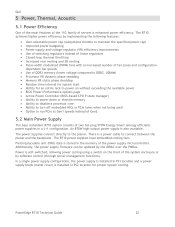
... thermal throttling Increased rear venting and 3D venting Pulse-width modulated (PWM) fans with an increased number of servers is stored in PS2 location for an entire rack to run ...power supplies connect directly to connect between the planar and the backplane. Field replaceable unit (FRU) data is enhanced power efficiency. PowerEdge R710 Technical Guide 22 In a single power supply configuration, the power supply ... efficient) power supplies in a 1+1 configuration. Dell 5 Power, Thermal, Acoustic 5.1 Power Efficiency One of the main features of the 11G family of...
... thermal throttling Increased rear venting and 3D venting Pulse-width modulated (PWM) fans with an increased number of servers is stored in PS2 location for an entire rack to run ...power supplies connect directly to connect between the planar and the backplane. Field replaceable unit (FRU) data is enhanced power efficiency. PowerEdge R710 Technical Guide 22 In a single power supply configuration, the power supply ... efficient) power supplies in a 1+1 configuration. Dell 5 Power, Thermal, Acoustic 5.1 Power Efficiency One of the main features of the 11G family of...


