
Hardware Manual
Page 6
... Card 90 Installing the Internal SD Flash Card 90 Removing the Internal SD Flash Card 91 Internal USB Memory Key 91 Internal USB Cable 93 Removing the Internal USB Cable 93 Installing the Internal USB Cable 93 Integrated Dell Remote Access Controller 6 (iDRAC6) Enterprise Card (Optional 94 Installing an iDRAC6 Enterprise Card 94 Removing an...
... Card 90 Installing the Internal SD Flash Card 90 Removing the Internal SD Flash Card 91 Internal USB Memory Key 91 Internal USB Cable 93 Removing the Internal USB Cable 93 Installing the Internal USB Cable 93 Integrated Dell Remote Access Controller 6 (iDRAC6) Enterprise Card (Optional 94 Installing an iDRAC6 Enterprise Card 94 Removing an...
Hardware Manual
Page 8
... System 153 Safety First-For You and Your System 153 Troubleshooting System Startup Failure 153 Troubleshooting External Connections 153 Troubleshooting the Video Subsystem 154 Troubleshooting a USB Device 154 Troubleshooting a Serial I/O Device 155 8 Contents
... System 153 Safety First-For You and Your System 153 Troubleshooting System Startup Failure 153 Troubleshooting External Connections 153 Troubleshooting the Video Subsystem 154 Troubleshooting a USB Device 154 Troubleshooting a Serial I/O Device 155 8 Contents
Hardware Manual
Page 9
...158 Troubleshooting System Cooling Problems 159 Troubleshooting a Fan 160 Troubleshooting System Memory 160 Troubleshooting an Internal SD Card 162 Troubleshooting an Internal USB Memory Key . . . . . 163 Troubleshooting an Optical Drive 164 Troubleshooting a Tape Backup Unit 165 Troubleshooting a Hard ... Expansion Cards 168 Troubleshooting the Processor(s 170 5 Running the System Diagnostics . . . . . 173 Using Dell™ PowerEdge™ Diagnostics 173 System Diagnostics Features 173 When to Use the System Diagnostics 174 Running the System Diagnostics 174 Contents 9
...158 Troubleshooting System Cooling Problems 159 Troubleshooting a Fan 160 Troubleshooting System Memory 160 Troubleshooting an Internal SD Card 162 Troubleshooting an Internal USB Memory Key . . . . . 163 Troubleshooting an Optical Drive 164 Troubleshooting a Tape Backup Unit 165 Troubleshooting a Hard ... Expansion Cards 168 Troubleshooting the Processor(s 170 5 Running the System Diagnostics . . . . . 173 Using Dell™ PowerEdge™ Diagnostics 173 System Diagnostics Features 173 When to Use the System Diagnostics 174 Running the System Diagnostics 174 Contents 9
Hardware Manual
Page 11
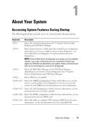
... more information. See the Unified Server Configurator user documentation for more information. These connections are both secure and temporary, and can access utilities such as USB devices attached to the system. For more information, see the documentation for your PERC card. About Your System Accessing System Features During Startup The following...
... more information. See the Unified Server Configurator user documentation for more information. These connections are both secure and temporary, and can access utilities such as USB devices attached to the system. For more information, see the documentation for your PERC card. About Your System Accessing System Features During Startup The following...
Hardware Manual
Page 13
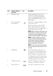
...Button, or Icon Connector 1 Information tag 2 Power-on indicator, power button 3 NMI button 4 USB connectors (2) 5 Video connector Description A slide-out label panel for five seconds. NOTE: To ..., Embedded NIC1 MAC address, and iDRAC6 Enterprise card MAC address. Connects USB devices to the system. The power button controls the DC power supply output to the system. The ports are... USB 2.0-complaint. Connects a monitor to the system is turned off the system using the power button...
...Button, or Icon Connector 1 Information tag 2 Power-on indicator, power button 3 NMI button 4 USB connectors (2) 5 Video connector Description A slide-out label panel for five seconds. NOTE: To ..., Embedded NIC1 MAC address, and iDRAC6 Enterprise card MAC address. Connects USB devices to the system. The power button controls the DC power supply output to the system. The ports are... USB 2.0-complaint. Connects a monitor to the system is turned off the system using the power button...
Hardware Manual
Page 20
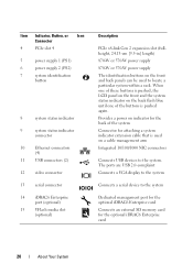
... (PS1) 6 power supply 2 (PS2) 7 system identification button 8 system status indicator 9 system status indicator connector 10 Ethernet connectors (4) 11 USB connectors (2) 12 video connector 13 serial connector 14 iDRAC6 Enterprise port (optional) 15 VFlash media slot (optional) Description PCIe x8-link Gen 2 ...The identification buttons on a cable management arm Integrated 10/100/1000 NIC connectors Connects USB devices to locate a particular system within a rack. The ports are USB 2.0-complaint Connects a VGA display to the system Connects a serial device to the system...
... (PS1) 6 power supply 2 (PS2) 7 system identification button 8 system status indicator 9 system status indicator connector 10 Ethernet connectors (4) 11 USB connectors (2) 12 video connector 13 serial connector 14 iDRAC6 Enterprise port (optional) 15 VFlash media slot (optional) Description PCIe x8-link Gen 2 ...The identification buttons on a cable management arm Integrated 10/100/1000 NIC connectors Connects USB devices to locate a particular system within a rack. The ports are USB 2.0-complaint Connects a VGA display to the system Connects a serial device to the system...
Hardware Manual
Page 32
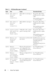
...See "Troubleshooting System Memory." 32 About Your System Reseat the cable. Error failure. detected during memory Check DIMMs. configuration. E2012 Memory configured but unusable. USB cable to the control panel is configuration not configurable. E2010 Memory not detected. See "Installing Memory Modules" or "Troubleshooting System Memory." Reseat the cable.... If the problem persists, replace cable. LCD Status Messages (continued) Code Text Cause Corrective Actions E1A14 SAS cable A failure. E1A1D Control panel USB cable not detected.
...See "Troubleshooting System Memory." 32 About Your System Reseat the cable. Error failure. detected during memory Check DIMMs. configuration. E2012 Memory configured but unusable. USB cable to the control panel is configuration not configurable. E2010 Memory not detected. See "Installing Memory Modules" or "Troubleshooting System Memory." Reseat the cable.... If the problem persists, replace cable. LCD Status Messages (continued) Code Text Cause Corrective Actions E1A14 SAS cable A failure. E1A1D Control panel USB cable not detected.
Hardware Manual
Page 41
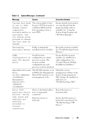
... identical. Embedded NICx and NICy: OS NIC=, Management Shared NIC= The OS NIC interface is non-UEFI. If a problem is set in BIOS. See "Troubleshooting a USB Device." See "Troubleshooting System Memory." Defective mouse or keyboard. Ensure that the proper bootable media is loose or improperly connected. Check the system management software...
... identical. Embedded NICx and NICy: OS NIC=, Management Shared NIC= The OS NIC interface is non-UEFI. If a problem is set in BIOS. See "Troubleshooting a USB Device." See "Troubleshooting System Memory." Defective mouse or keyboard. Ensure that the proper bootable media is loose or improperly connected. Check the system management software...
Hardware Manual
Page 42
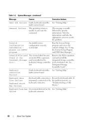
... controller failure Faulty keyboard controller; faulty system board Keyboard data line failure Keyboard stuck key failure Keyboard cable connector is Reseat the keyboard cable. "Troubleshooting a USB Device." failed keyboard connector. 42 About Your System
... controller failure Faulty keyboard controller; faulty system board Keyboard data line failure Keyboard stuck key failure Keyboard cable connector is Reseat the keyboard cable. "Troubleshooting a USB Device." failed keyboard connector. 42 About Your System
Hardware Manual
Page 43
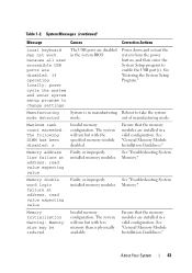
... System installed memory modules. Memory Initialization Warning: Memory size may not work because all user accessible USB ports are disabled in a valid configuration. The USB ports are disabled. out of manufacturing mode. The following DIMM has been disabled: x Invalid memory...Entering the System Setup Program." Memory." If operating locally, power cycle the system and enter system setup program to enable the USB port(s). Memory address line failure at address, read value expecting value Faulty or improperly See "Troubleshooting System installed memory modules....
... System installed memory modules. Memory Initialization Warning: Memory size may not work because all user accessible USB ports are disabled in a valid configuration. The USB ports are disabled. out of manufacturing mode. The following DIMM has been disabled: x Invalid memory...Entering the System Setup Program." Memory." If operating locally, power cycle the system and enter system setup program to enable the USB port(s). Memory address line failure at address, read value expecting value Faulty or improperly See "Troubleshooting System installed memory modules....
Hardware Manual
Page 45
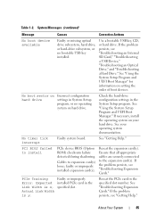
... configuration hard drive settings in the Link Width is y. About Your System 45 Table 1-2. Use a bootable USB key, CD, or hard drive. PCIe Training Faulty or improperly Error: Expected installed PCIe card in System Setup program, or ... Boot Manager" for information on your operating system documentation. If the problem persists, see "Troubleshooting an Internal SD Card," "Troubleshooting a USB Device," "Troubleshooting an Optical Drive," and "Troubleshooting a Hard Drive." Ensure that all appropriate cables are securely connected to expansion card(s)...
... configuration hard drive settings in the Link Width is y. About Your System 45 Table 1-2. Use a bootable USB key, CD, or hard drive. PCIe Training Faulty or improperly Error: Expected installed PCIe card in System Setup program, or ... Boot Manager" for information on your operating system documentation. If the problem persists, see "Troubleshooting an Internal SD Card," "Troubleshooting a USB Device," "Troubleshooting an Optical Drive," and "Troubleshooting a Hard Drive." Ensure that all appropriate cables are securely connected to expansion card(s)...
Hardware Manual
Page 46
...Your System See defective. SATA Portx device There is connected. If the problem persists, see "Troubleshooting Expansion Cards." optical drive, or USB device, Ensure that the memory modules are properly or the requested sector is no device connected Information only. See "General Memory Module... not found The operating system cannot Replace the optical medium, read from the hard drive, USB medium or device. Table 1-2. Ensure that the SAS the system could not find a backplane, USB, or SATA particular sector on the disk, cables are installed in the clear position (pins ...
...Your System See defective. SATA Portx device There is connected. If the problem persists, see "Troubleshooting Expansion Cards." optical drive, or USB device, Ensure that the memory modules are properly or the requested sector is no device connected Information only. See "General Memory Module... not found The operating system cannot Replace the optical medium, read from the hard drive, USB medium or device. Table 1-2. Ensure that the SAS the system could not find a backplane, USB, or SATA particular sector on the disk, cables are installed in the clear position (pins ...
Hardware Manual
Page 47
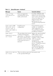
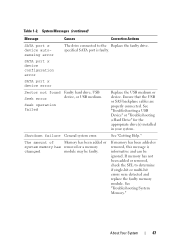
... SAS backplane cables are properly connected. See "Troubleshooting a USB Device" or "Troubleshooting a Hard Drive" for the appropriate drive(s) installed in your system. The amount of Memory has been added or system memory has removed ... if single-bit or multi-bit errors were detected and replace the faulty memory module. Shutdown failure General system error. Seek operation failed Replace the USB medium or device. See "Getting Help." specified SATA port is informative and can be faulty. SATA port x device configuration error SATA port x device error Sector...
... SAS backplane cables are properly connected. See "Troubleshooting a USB Device" or "Troubleshooting a Hard Drive" for the appropriate drive(s) installed in your system. The amount of Memory has been added or system memory has removed ... if single-bit or multi-bit errors were detected and replace the faulty memory module. Shutdown failure General system error. Seek operation failed Replace the USB medium or device. See "Getting Help." specified SATA port is informative and can be faulty. SATA port x device configuration error SATA port x device error Sector...
Hardware Manual
Page 53
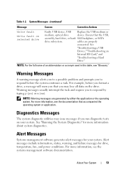
See "Troubleshooting a USB Device," "Troubleshooting an Internal SD Card," and "Troubleshooting a Hard Drive." Warning Messages A warning message alerts you to..., or SATA drive subsystem. Warning messages usually interrupt the task and require you run diagnostic tests on selected drive Faulty USB device, USB Replace the USB medium or medium, optical drive device. For example, before you format a drive, a message will warn you that you... For the full name of an abbreviation or acronym used in this table, see the documentation that the USB, assembly, hard drive, or hard-
See "Troubleshooting a USB Device," "Troubleshooting an Internal SD Card," and "Troubleshooting a Hard Drive." Warning Messages A warning message alerts you to..., or SATA drive subsystem. Warning messages usually interrupt the task and require you run diagnostic tests on selected drive Faulty USB device, USB Replace the USB medium or medium, optical drive device. For example, before you format a drive, a message will warn you that you... For the full name of an abbreviation or acronym used in this table, see the documentation that the USB, assembly, hard drive, or hard-
Hardware Manual
Page 56
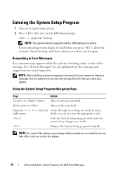
... Setup Program 1 Turn on or restart your system. 2 Press after you see the following message: = System Setup NOTE: The system will not respond until the USB keyboard is booting, make are recorded but do not take effect until you restart the system. 56 Using the System Setup Program and UEFI Boot...
... Setup Program 1 Turn on or restart your system. 2 Press after you see the following message: = System Setup NOTE: The system will not respond until the USB keyboard is booting, make are recorded but do not take effect until you restart the system. 56 Using the System Setup Program and UEFI Boot...
Hardware Manual
Page 61
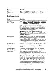
... device. Auto automatically chooses the appropriate emulation type for the device, except for a USB flash drive. Boot Settings Screen Option Boot Mode (BIOS default) Boot Sequence Hard-Disk Drive Sequence USB Flash Drive Emulation Type (Auto default) Description CAUTION: Switching the boot mode could prevent... the system from hard drives in the same boot mode. Floppy allows the USB flash drive to boot from booting if the operating system was not installed in the system during system startup. Determines the emulation ...
... device. Auto automatically chooses the appropriate emulation type for the device, except for a USB flash drive. Boot Settings Screen Option Boot Mode (BIOS default) Boot Sequence Hard-Disk Drive Sequence USB Flash Drive Emulation Type (Auto default) Description CAUTION: Switching the boot mode could prevent... the system from hard drives in the same boot mode. Floppy allows the USB flash drive to boot from booting if the operating system was not installed in the system during system startup. Determines the emulation ...
Hardware Manual
Page 62
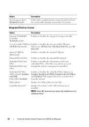
...Screen Option Description Integrated SAS/RAID Controller (Enabled default) Enables or disables the integrated storage controller. User Accessible USB Ports Enables or disables the user-accessible USB ports. (All Ports On default) Options are Enabled, Enabled with PXE, Enabled with PXE; Internal...USB port. MAC Address Displays the MAC address for the NIC. Capability Detected Displays the features of an additional driver. 62 Using the System Setup Program and UEFI Boot Manager NOTE: Some NIC features may also be accessed through the system's management controller.) Embedded Gb ...
...Screen Option Description Integrated SAS/RAID Controller (Enabled default) Enables or disables the integrated storage controller. User Accessible USB Ports Enables or disables the user-accessible USB ports. (All Ports On default) Options are Enabled, Enabled with PXE, Enabled with PXE; Internal...USB port. MAC Address Displays the MAC address for the NIC. Capability Detected Displays the features of an additional driver. 62 Using the System Setup Program and UEFI Boot Manager NOTE: Some NIC features may also be accessed through the system's management controller.) Embedded Gb ...
Hardware Manual
Page 68
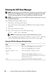
... then restart your operating system begins to load before you see the following message: = UEFI Boot Manager NOTE: The system will not respond until the USB keyboard is active. Using the UEFI Boot Manager Navigation Keys Keys Up arrow Down arrow Spacebar, Action Moves to and highlights the next field. Cycles...
... then restart your operating system begins to load before you see the following message: = UEFI Boot Manager NOTE: The system will not respond until the USB keyboard is active. Using the UEFI Boot Manager Navigation Keys Keys Up arrow Down arrow Spacebar, Action Moves to and highlights the next field. Cycles...
Hardware Manual
Page 76
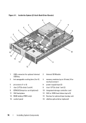
Figure 3-1. Inside the System (2.5-Inch Hard-Drive Chassis) 6 5 4 3 2 1 7 8 9 16 15 14 13 12 10 11 1 USB connector for optional internal USB key 3 hot-swappable cooling fans (4 or 5) 5 processors (1 or 2) 7 riser 2 (PCIe slots 3 and 4) 9 iDRAC6 Enterprise card (optional) 11 SAS backplane 13 RAID battery (PERC only) 15 ...
Figure 3-1. Inside the System (2.5-Inch Hard-Drive Chassis) 6 5 4 3 2 1 7 8 9 16 15 14 13 12 10 11 1 USB connector for optional internal USB key 3 hot-swappable cooling fans (4 or 5) 5 processors (1 or 2) 7 riser 2 (PCIe slots 3 and 4) 9 iDRAC6 Enterprise card (optional) 11 SAS backplane 13 RAID battery (PERC only) 15 ...
Hardware Manual
Page 91
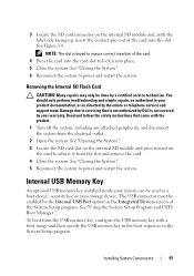
... the System Setup program. See "Closing the System." 6 Reconnect the system to power and restart the system. To boot from the USB memory key, configure the USB memory key with the product. 1 Turn off the system, including any attached peripherals, and disconnect the system from the slot and remove... 3 Locate the SD card connector on the card to release it into the slot. Read and follow the safety instructions that is not authorized by Dell is keyed to ensure correct insertion of the card into place. 5 Close the system. See "Closing the System." 5 Reconnect the system to power...
... the System Setup program. See "Closing the System." 6 Reconnect the system to power and restart the system. To boot from the USB memory key, configure the USB memory key with the product. 1 Turn off the system, including any attached peripherals, and disconnect the system from the slot and remove... 3 Locate the SD card connector on the card to release it into the slot. Read and follow the safety instructions that is not authorized by Dell is keyed to ensure correct insertion of the card into place. 5 Close the system. See "Closing the System." 5 Reconnect the system to power...

