Quick Reference Guide
Page 13
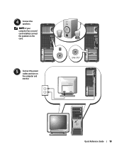
Quick Reference Guide 13 NOTE: If your computer has a sound card installed, connect the speakers to the card. 5 Connect the power cables and turn on the computer and monitor. 4 Connect the speakers.
Quick Reference Guide 13 NOTE: If your computer has a sound card installed, connect the speakers to the card. 5 Connect the power cables and turn on the computer and monitor. 4 Connect the speakers.
Quick Reference Guide
Page 18
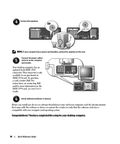
... 1394 card, see your computer and operating system. NOTE: If your desktop computer. 18 Quick Reference Guide To purchase a card, contact Dell. Connect the power cables 5 and turn on contacting Dell and for your computer has a sound card installed, connect the speakers to verify that the software or device is only available if...
... 1394 card, see your computer and operating system. NOTE: If your desktop computer. 18 Quick Reference Guide To purchase a card, contact Dell. Connect the power cables 5 and turn on contacting Dell and for your computer has a sound card installed, connect the speakers to verify that the software or device is only available if...
Quick Reference Guide
Page 20
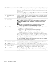
...the computer sends or receives data over a network connection. To exit from a power-saving mode, see "Power Management" in , and turn the badge. 7 USB 2.0 connectors (2) 8 Dell badge rotation notch 9 power button 10 power light 11 microphone connector 12 headphone connector 13 diagnostic lights (4) 14 network link light...See "Diagnostic Lights" on booting to place it is on page 37. You can also be on when a network device is in a power-saving mode. • Blinking or solid amber - The computer is turned off . The computer is establishing a network connection. 20 Quick ...
...the computer sends or receives data over a network connection. To exit from a power-saving mode, see "Power Management" in , and turn the badge. 7 USB 2.0 connectors (2) 8 Dell badge rotation notch 9 power button 10 power light 11 microphone connector 12 headphone connector 13 diagnostic lights (4) 14 network link light...See "Diagnostic Lights" on booting to place it is on page 37. You can also be on when a network device is in a power-saving mode. • Blinking or solid amber - The computer is turned off . The computer is establishing a network connection. 20 Quick ...
Quick Reference Guide
Page 21
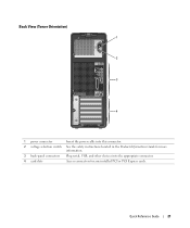
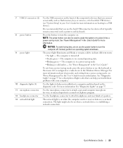
Back View (Tower Orientation) 1 2 3 4 1 power connector Insert the power cable into this connector. 2 voltage selection switch See the safety instructions located in the Product Information Guide for more information. 3 back-panel connectors Plug serial, USB, and other devices into the appropriate connector. 4 card slots Access connectors for any installed PCI or PCI Express cards. Quick Reference Guide 21
Back View (Tower Orientation) 1 2 3 4 1 power connector Insert the power cable into this connector. 2 voltage selection switch See the safety instructions located in the Product Information Guide for more information. 3 back-panel connectors Plug serial, USB, and other devices into the appropriate connector. 4 card slots Access connectors for any installed PCI or PCI Express cards. Quick Reference Guide 21
Quick Reference Guide
Page 23
... might also be used to wake the system or to turn the computer on. Quick Reference Guide 23 7 USB 2.0 connectors (2) 8 power button 9 power light 10 diagnostic lights (4) 11 microphone connector 12 headphone connector 13 network link light Use the USB connectors on the front of the computer... for devices that you connect occasionally, such as flash memory keys or cameras, or for bootable USB devices (see "Power Management" in a power-saving mode. • Blinking or solid amber - Press this button to a USB device). The computer is recommended that you use ...
... might also be used to wake the system or to turn the computer on. Quick Reference Guide 23 7 USB 2.0 connectors (2) 8 power button 9 power light 10 diagnostic lights (4) 11 microphone connector 12 headphone connector 13 network link light Use the USB connectors on the front of the computer... for devices that you connect occasionally, such as flash memory keys or cameras, or for bootable USB devices (see "Power Management" in a power-saving mode. • Blinking or solid amber - Press this button to a USB device). The computer is recommended that you use ...
Quick Reference Guide
Page 24
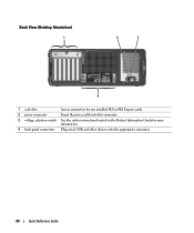
Back View (Desktop Orientation) 1 2 3 4 1 card slots Access connectors for any installed PCI or PCI Express cards. 2 power connector Insert the power cable into this connector. 3 voltage selection switch See the safety instructions located in the Product Information Guide for more information. 4 back-panel connectors Plug serial, USB, and other devices into the appropriate connector. 24 Quick Reference Guide
Back View (Desktop Orientation) 1 2 3 4 1 card slots Access connectors for any installed PCI or PCI Express cards. 2 power connector Insert the power cable into this connector. 3 voltage selection switch See the safety instructions located in the Product Information Guide for more information. 4 back-panel connectors Plug serial, USB, and other devices into the appropriate connector. 24 Quick Reference Guide
Quick Reference Guide
Page 27
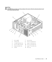
Inside View CAUTION: Before you begin any of the procedures in this section, follow the safety instructions located in the Product Information Guide. 1 2 12 11 10 9 8 7 3 4 5 6 1 power supply 2 system board 3 secondary hard drive bay 4 processor airflow shroud 5 primary hard drive bay 6 card fan 7 processor fan 8 lower 3.5 inch drive bay 9 upper 3.5 inch drive bay 10 lower 5.25 inch drive bay 11 upper 5.25 inch drive bay 12 drive cage Quick Reference Guide 27
Inside View CAUTION: Before you begin any of the procedures in this section, follow the safety instructions located in the Product Information Guide. 1 2 12 11 10 9 8 7 3 4 5 6 1 power supply 2 system board 3 secondary hard drive bay 4 processor airflow shroud 5 primary hard drive bay 6 card fan 7 processor fan 8 lower 3.5 inch drive bay 9 upper 3.5 inch drive bay 10 lower 5.25 inch drive bay 11 upper 5.25 inch drive bay 12 drive cage Quick Reference Guide 27
Quick Reference Guide
Page 29
... (12VPOWER) 2 memory module connectors 3 battery socket (BATTERY) 4 memory fan connector (FAN_MEM) 5 front panel connector 6 main power connector (POWER) 7 IDE drive connector (IDE) 8 SATA connectors (SATA-1, SATA-3, SATA-0, SATA-2) 9 RTC reset jumper (RTCRST) 10 Flexbay connector (FLEXBAY) 11 ...memory, cards, drives, the microprocessor, and the battery • Information for troubleshooting various computer problems • Instructions for using the Dell Diagnostics and reinstalling drivers • Information on how to contact Dell You can access the User's Guide from your hard drive or the...
... (12VPOWER) 2 memory module connectors 3 battery socket (BATTERY) 4 memory fan connector (FAN_MEM) 5 front panel connector 6 main power connector (POWER) 7 IDE drive connector (IDE) 8 SATA connectors (SATA-1, SATA-3, SATA-0, SATA-2) 9 RTC reset jumper (RTCRST) 10 Flexbay connector (FLEXBAY) 11 ...memory, cards, drives, the microprocessor, and the battery • Information for troubleshooting various computer problems • Instructions for using the Dell Diagnostics and reinstalling drivers • Information on how to contact Dell You can access the User's Guide from your hard drive or the...
Quick Reference Guide
Page 36
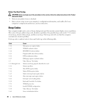
... register failure Master DMA register failure Master interrupt mask register failure Slave interrupt mask register failure Interrupt vector loading failure Keyboard Controller Test failure NVRAM power loss Invalid NVRAM configuration Video Memory Test failure Screen initialization failure 36 Quick Reference Guide Before You Start Testing CAUTION: Before you that the computer...
... register failure Master DMA register failure Master interrupt mask register failure Slave interrupt mask register failure Interrupt vector loading failure Keyboard Controller Test failure NVRAM power loss Invalid NVRAM configuration Video Memory Test failure Screen initialization failure 36 Quick Reference Guide Before You Start Testing CAUTION: Before you that the computer...
Quick Reference Guide
Page 37
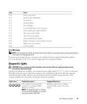
.... Quick Reference Guide 37 NOTE: The diagnostic lights turn off Plug the computer into a working condition or a possible pre-BIOS electrical outlet and press the power failure has occurred. See "Error Messages" in the User's Guide for either the operating system or the program that was running when the message appeared...
.... Quick Reference Guide 37 NOTE: The diagnostic lights turn off Plug the computer into a working condition or a possible pre-BIOS electrical outlet and press the power failure has occurred. See "Error Messages" in the User's Guide for either the operating system or the program that was running when the message appeared...
Quick Reference Guide
Page 39
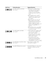
... more information on removing a card, see "Resolving Software and Hardware Incompatibilities" on page 32). 4 If the problem persists, contact Dell. A possible USB failure has occurred. If the computer starts normally, troubleshoot the last card removed from the computer for each card...remove a different card, and then restart the computer. 3 Repeat this process for resource conflicts (see your User's Guide. Reinstall all power and data cables and restart the computer. Quick Reference Guide 39 A possible graphics card failure has occurred. Suggested Resolution 1 Determine if...
... more information on removing a card, see "Resolving Software and Hardware Incompatibilities" on page 32). 4 If the problem persists, contact Dell. A possible USB failure has occurred. If the computer starts normally, troubleshoot the last card removed from the computer for each card...remove a different card, and then restart the computer. 3 Repeat this process for resource conflicts (see your User's Guide. Reinstall all power and data cables and restart the computer. Quick Reference Guide 39 A possible graphics card failure has occurred. Suggested Resolution 1 Determine if...
Quick Reference Guide
Page 45
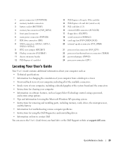
..., 26 line-out, 26 mouse, 25 network adapter, 26 parallel, 25 power, 21, 24 serial, 26 sound, 26 USB, 20, 23, 26 D Dell support site, 7 Dell Diagnostics, 34 Dell Premier Support website, 6-7 diagnostic lights, 37 diagnostics beep codes, 36 Dell, 34 Drivers and Utilities CD, 5 lights, 20, 23, 37 documentation ... activity light, 19, 22 eject button, 19, 22 H hard drive activity light, 19-20, 22-23 hardware beep codes, 36 conflicts, 32 Dell Diagnostics, 34 Hardware Troubleshooter, 32 headphone connector, 20, 23 Help and Support Center, 7 I IEEE connectors, 19, 22 installing parts turning off your...
..., 26 line-out, 26 mouse, 25 network adapter, 26 parallel, 25 power, 21, 24 serial, 26 sound, 26 USB, 20, 23, 26 D Dell support site, 7 Dell Diagnostics, 34 Dell Premier Support website, 6-7 diagnostic lights, 37 diagnostics beep codes, 36 Dell, 34 Drivers and Utilities CD, 5 lights, 20, 23, 37 documentation ... activity light, 19, 22 eject button, 19, 22 H hard drive activity light, 19-20, 22-23 hardware beep codes, 36 conflicts, 32 Dell Diagnostics, 34 Hardware Troubleshooter, 32 headphone connector, 20, 23 Help and Support Center, 7 I IEEE connectors, 19, 22 installing parts turning off your...
Quick Reference Guide
Page 46
...board mouse connector, 25 N network connector, 26 O Operating System CD, 8 Installation Guide, 8 P power button, 20, 23 connector, 21, 24 light, 20, 23 problems beep codes, 36 conflicts, 32 Dell Diagnostics, 34 diagnostic lights, 37 restore to previous state, 32 R reinstalling Drivers and Utilities CD, ... 6 software conflicts, 32 sound connectors line-in, 26 line-out, 26 system board, 28 System Restore, 32 T troubleshooting conflicts, 32 Dell Diagnostics, 34 diagnostic lights, 37 Hardware Troubleshooter, 32 Help and Support Center, 7 restore to previous state, 32 U USB connector, 26 connectors...
...board mouse connector, 25 N network connector, 26 O Operating System CD, 8 Installation Guide, 8 P power button, 20, 23 connector, 21, 24 light, 20, 23 problems beep codes, 36 conflicts, 32 Dell Diagnostics, 34 diagnostic lights, 37 restore to previous state, 32 R reinstalling Drivers and Utilities CD, ... 6 software conflicts, 32 sound connectors line-in, 26 line-out, 26 system board, 28 System Restore, 32 T troubleshooting conflicts, 32 Dell Diagnostics, 34 diagnostic lights, 37 Hardware Troubleshooter, 32 Help and Support Center, 7 restore to previous state, 32 U USB connector, 26 connectors...


