
Quick Reference Guide
Page 7
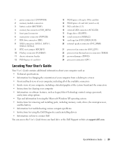
... call and order status, warranty, and repair information • Service and support - support.dell.com NOTE: Select your computer, you reinstall the operating system for devices (such as memory, the hard drive, and the operating system • Customer Care - What Are You... drives, and USB devices. The software automatically detects your computer and operating system and installs the updates appropriate for your Dell computer. DSS provides critical updates for your problem. 4 Follow the instructions on my computer configuration, product specifications, and white...
... call and order status, warranty, and repair information • Service and support - support.dell.com NOTE: Select your computer, you reinstall the operating system for devices (such as memory, the hard drive, and the operating system • Customer Care - What Are You... drives, and USB devices. The software automatically detects your computer and operating system and installs the updates appropriate for your Dell computer. DSS provides critical updates for your problem. 4 Follow the instructions on my computer configuration, product specifications, and white...
Quick Reference Guide
Page 20
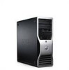
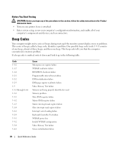
...NOTE: The power button can also be on when the computer sends or receives data over a network connection. The computer is configured as flash memory keys or cameras, or for bootable USB devices (see "System Setup" in your User's Guide for more information. To exit from a power...The computer is recommended that you use the keyboard or the mouse if it into a sound or telephony program. 7 USB 2.0 connectors (2) 8 Dell badge rotation notch 9 power button 10 power light 11 microphone connector 12 headphone connector 13 diagnostic lights (4) 14 network link light Use the USB ...
...NOTE: The power button can also be on when the computer sends or receives data over a network connection. The computer is configured as flash memory keys or cameras, or for bootable USB devices (see "System Setup" in your User's Guide for more information. To exit from a power...The computer is recommended that you use the keyboard or the mouse if it into a sound or telephony program. 7 USB 2.0 connectors (2) 8 Dell badge rotation notch 9 power button 10 power light 11 microphone connector 12 headphone connector 13 diagnostic lights (4) 14 network link light Use the USB ...
Quick Reference Guide
Page 23
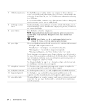
... headphone connector 13 network link light Use the USB connectors on the front of the computer for devices that you connect occasionally, such as flash memory keys or cameras, or for bootable USB devices (see "Power Management" in the User's Guide for more information.
... headphone connector 13 network link light Use the USB connectors on the front of the computer for devices that you connect occasionally, such as flash memory keys or cameras, or for bootable USB devices (see "Power Management" in the User's Guide for more information.
Quick Reference Guide
Page 26
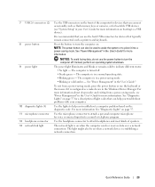
... is recommended that you use the front USB connectors for devices that typically remain connected, such as flash memory keys or cameras, or for bootable USB devices. If you connect occasionally, such as flash memory keys or cameras., or for devices that typically remain connected, such as a cassette player, CD player, or...
... is recommended that you use the front USB connectors for devices that typically remain connected, such as flash memory keys or cameras, or for bootable USB devices. If you connect occasionally, such as flash memory keys or cameras., or for devices that typically remain connected, such as a cassette player, CD player, or...
Quick Reference Guide
Page 29
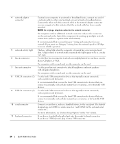
1 power connector (12VPOWER) 2 memory module connectors 3 battery socket (BATTERY) 4 memory fan connector (FAN_MEM) 5 front panel connector 6 main power connector (POWER) 7 IDE drive connector (IDE) 8 SATA connectors (SATA-1, SATA-3, SATA-0, SATA-2) 9 RTC reset jumper... system setup options • Tips and information for using the Microsoft Windows XP operating system • Instructions for removing and installing parts, including memory, cards, drives, the microprocessor, and the battery • Information for troubleshooting various computer problems • Instructions for using the...
1 power connector (12VPOWER) 2 memory module connectors 3 battery socket (BATTERY) 4 memory fan connector (FAN_MEM) 5 front panel connector 6 main power connector (POWER) 7 IDE drive connector (IDE) 8 SATA connectors (SATA-1, SATA-3, SATA-0, SATA-2) 9 RTC reset jumper... system setup options • Tips and information for using the Microsoft Windows XP operating system • Instructions for removing and installing parts, including memory, cards, drives, the microprocessor, and the battery • Information for troubleshooting various computer problems • Instructions for using the...
Quick Reference Guide
Page 36
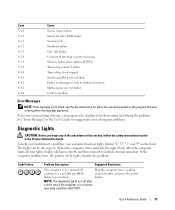
... failure Programmable interval timer failure DMA initialization failure DMA page register read/write failure Video Memory Test failure Memory not being properly identified or used Memory problem Slave DMA register failure Master DMA register failure Master interrupt mask register failure Slave ...interrupt mask register failure Interrupt vector loading failure Keyboard Controller Test failure NVRAM power loss Invalid NVRAM configuration Video Memory Test failure Screen initialization failure 36 Quick Reference Guide One possible beep code (code 1-3-1) consists of one beep, a ...
... failure Programmable interval timer failure DMA initialization failure DMA page register read/write failure Video Memory Test failure Memory not being properly identified or used Memory problem Slave DMA register failure Master DMA register failure Master interrupt mask register failure Slave ...interrupt mask register failure Interrupt vector loading failure Keyboard Controller Test failure NVRAM power loss Invalid NVRAM configuration Video Memory Test failure Screen initialization failure 36 Quick Reference Guide One possible beep code (code 1-3-1) consists of one beep, a ...
Quick Reference Guide
Page 37
... on the monitor identifying the problem. To help you begin any of the procedures in this section, follow the safety instructions located in protected mode Memory failure above address 0FFFFh Timer-chip counter 2 failure Time-of the lights identify the problem. When the computer starts normally, the lights flash. button...-BIOS electrical outlet and press the power failure has occurred. If an error occurs during start-up, a message may be off to shadowed memory Math-coprocessor test failure Cache test failure Error Messages NOTE: If the message is in a normal off after POST.
... on the monitor identifying the problem. To help you begin any of the procedures in this section, follow the safety instructions located in protected mode Memory failure above address 0FFFFh Timer-chip counter 2 failure Time-of the lights identify the problem. When the computer starts normally, the lights flash. button...-BIOS electrical outlet and press the power failure has occurred. If an error occurs during start-up, a message may be off to shadowed memory Math-coprocessor test failure Cache test failure Error Messages NOTE: If the message is in a normal off after POST.
Quick Reference Guide
Page 38
... your computer is successfully communicating with the remaining memory modules until new memory modules are not defective. 8 When the defective memory module is identified, contact Dell for instructions. 7 If the memory module passes, shut down the computer, remove the memory module, and then repeat the process with the memory. 2 Restart the computer. 3 If the problem still exists...
... your computer is successfully communicating with the remaining memory modules until new memory modules are not defective. 8 When the defective memory module is identified, contact Dell for instructions. 7 If the memory module passes, shut down the computer, remove the memory module, and then repeat the process with the memory. 2 Restart the computer. 3 If the problem still exists...
Quick Reference Guide
Page 40
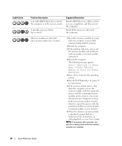
.... Light Pattern Problem Description No memory modules are installed. Please Populate Memory in memory module connector 4. 4 Restart the computer. See page 34 for technical assistance. If the first memory module tested is successfully communicating with the remaining memory modules until new memory modules are detected. Contact Dell for instructions. 7 If the memory module passes, shut down the computer...
.... Light Pattern Problem Description No memory modules are installed. Please Populate Memory in memory module connector 4. 4 Restart the computer. See page 34 for technical assistance. If the first memory module tested is successfully communicating with the remaining memory modules until new memory modules are detected. Contact Dell for instructions. 7 If the memory module passes, shut down the computer...
Quick Reference Guide
Page 41
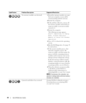
...conflicts (see "Resolving Software and Hardware Incompatibilities" on contacting Dell, see your computer. • Reinstall the memory modules and restart the computer. • If the problem persists, contact Dell. If the computer starts normally, troubleshoot the last card ...problem persists, contact Dell. Light Pattern Problem Description Suggested Resolution Memory modules are detected, but a memory configuration or compatibility error exists. • Ensure that no special memory module/memory connector placement requirements exist. • Verify that the memory modules that you ...
...conflicts (see "Resolving Software and Hardware Incompatibilities" on contacting Dell, see your computer. • Reinstall the memory modules and restart the computer. • If the problem persists, contact Dell. If the computer starts normally, troubleshoot the last card ...problem persists, contact Dell. Light Pattern Problem Description Suggested Resolution Memory modules are detected, but a memory configuration or compatibility error exists. • Ensure that no special memory module/memory connector placement requirements exist. • Verify that the memory modules that you ...


