Quick Reference Guide
Page 3
... Problems 32 Troubleshooting Tips 32 Resolving Software and Hardware Incompatibilities 32 Using Microsoft Windows XP System Restore 32 Using the Last Known Good Configuration 34 Dell Diagnostics 34 Before You Start Testing 36 Beep Codes 36 Error Messages 37 Diagnostic Lights 37 Frequently Asked Questions 42 Index 45 Contents 3
... Problems 32 Troubleshooting Tips 32 Resolving Software and Hardware Incompatibilities 32 Using Microsoft Windows XP System Restore 32 Using the Last Known Good Configuration 34 Dell Diagnostics 34 Before You Start Testing 36 Beep Codes 36 Error Messages 37 Diagnostic Lights 37 Frequently Asked Questions 42 Index 45 Contents 3
Quick Reference Guide
Page 5
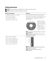
...Basic troubleshooting information • How to care for your computer. You can use the CD to reinstall drivers, run the Dell Diagnostics • Error codes and diagnostic lights • How to remove and install parts • How to open my computer cover NOTE: Drivers and documentation updates can...advanced technical-reference material for technicians or experienced users. • How to set up my computer • How to run the "Dell Diagnostics" on your computer. Readme files may not ship with your computer or in certain countries. Quick Reference Guide NOTE: The Quick ...
...Basic troubleshooting information • How to care for your computer. You can use the CD to reinstall drivers, run the Dell Diagnostics • Error codes and diagnostic lights • How to remove and install parts • How to open my computer cover NOTE: Drivers and documentation updates can...advanced technical-reference material for technicians or experienced users. • How to set up my computer • How to run the "Dell Diagnostics" on your computer. Readme files may not ship with your computer or in certain countries. Quick Reference Guide NOTE: The Quick ...
Quick Reference Guide
Page 20
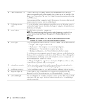
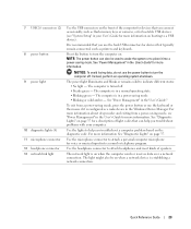
... personal computer microphone for devices that typically remain connected, such as flash memory keys or cameras, or for bootable USB devices (see "Diagnostic Lights" on . See "Power Problems" in a power-saving mode. • Blinking or solid amber - Use the microphone connector to ...a normal operating state. • Blinking green - 7 USB 2.0 connectors (2) 8 Dell badge rotation notch 9 power button 10 power light 11 microphone connector 12 headphone connector 13 diagnostic lights (4) 14 network link light Use the USB connectors on the front of your computer for devices that you connect ...
... personal computer microphone for devices that typically remain connected, such as flash memory keys or cameras, or for bootable USB devices (see "Diagnostic Lights" on . See "Power Problems" in a power-saving mode. • Blinking or solid amber - Use the microphone connector to ...a normal operating state. • Blinking green - 7 USB 2.0 connectors (2) 8 Dell badge rotation notch 9 power button 10 power light 11 microphone connector 12 headphone connector 13 diagnostic lights (4) 14 network link light Use the USB connectors on the front of your computer for devices that you connect ...
Quick Reference Guide
Page 23
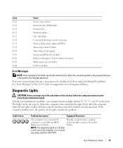
...losing data, do not use the power button to help you troubleshoot a computer problem based on the diagnostic code. See "Diagnostic Lights" on page 37 for a description of light codes that can also be on when a network device is on when the computer sends or receives ...the headphone connector to indicate different states: • No light - See "Power Management" in the User's Guide." 7 USB 2.0 connectors (2) 8 power button 9 power light 10 diagnostic lights (4) 11 microphone connector 12 headphone connector 13 network link light Use the USB connectors on the front of the computer ...
...losing data, do not use the power button to help you troubleshoot a computer problem based on the diagnostic code. See "Diagnostic Lights" on page 37 for a description of light codes that can also be on when a network device is on when the computer sends or receives ...the headphone connector to indicate different states: • No light - See "Power Management" in the User's Guide." 7 USB 2.0 connectors (2) 8 power button 9 power light 10 diagnostic lights (4) 11 microphone connector 12 headphone connector 13 network link light Use the USB connectors on the front of the computer ...
Quick Reference Guide
Page 37
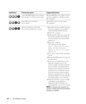
... test failure Failure to decompress code to indicate normal operation. After the computer starts, all four lights display solid green briefly and then turn off or green. NOTE: The diagnostic lights turn off Plug the computer into a working condition or a possible pre-BIOS electrical outlet and... press the power failure has occurred. When the computer starts normally, the lights flash. If an error occurs during start-up, ...
... test failure Failure to decompress code to indicate normal operation. After the computer starts, all four lights display solid green briefly and then turn off or green. NOTE: The diagnostic lights turn off Plug the computer into a working condition or a possible pre-BIOS electrical outlet and... press the power failure has occurred. When the computer starts normally, the lights flash. If an error occurs during start-up, ...
Quick Reference Guide
Page 38
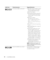
...modules are detected, but a memory failure has occurred. 1 Reseat the memory modules to the operating system. 6 Run the Dell Diagnostics. Please Populate Memory in Pairs for Normal Operation. 5 Press to boot to ensure that the remaining modules are installed. 38... can operate in the recovery mode. Light Pattern Problem Description A possible BIOS failure has occurred; A possible processor failure has occurred. For instructions on contacting Dell, see your computer is in debug mode until a memory error occurs during start-up or diagnostic testing. See page 34 for recovery...
...modules are detected, but a memory failure has occurred. 1 Reseat the memory modules to the operating system. 6 Run the Dell Diagnostics. Please Populate Memory in Pairs for Normal Operation. 5 Press to boot to ensure that the remaining modules are installed. 38... can operate in the recovery mode. Light Pattern Problem Description A possible BIOS failure has occurred; A possible processor failure has occurred. For instructions on contacting Dell, see your computer is in debug mode until a memory error occurs during start-up or diagnostic testing. See page 34 for recovery...
Quick Reference Guide
Page 40
Light Pattern Problem Description No memory modules are installed. See ... Please Populate Memory in debug mode until a memory error occurs during start-up or diagnostic testing. Contact Dell for a replacement.For instructions on contacting Dell, see your User's Guide. If the first memory module tested is defective, repeat...the memory modules and install one memory module in Debug Mode. For instructions on contacting Dell, see your computer is identified, contact Dell for technical assistance. Suggested Resolution 1 Reseat the memory modules to ensure that the remaining ...
Light Pattern Problem Description No memory modules are installed. See ... Please Populate Memory in debug mode until a memory error occurs during start-up or diagnostic testing. Contact Dell for a replacement.For instructions on contacting Dell, see your User's Guide. If the first memory module tested is defective, repeat...the memory modules and install one memory module in Debug Mode. For instructions on contacting Dell, see your computer is identified, contact Dell for technical assistance. Suggested Resolution 1 Reseat the memory modules to ensure that the remaining ...
Quick Reference Guide
Page 42
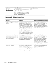
... branches into two connectors (plug these connectors into the monitor cables). Light Pattern Problem Description Suggested Resolution The computer is in a normal operating condition after POST. NOTE: The diagnostic lights turn off after POST. Connect my monitor when the monitor cable connector... doesn't seem to your User's Guide. For information on the back of my computer? computer, see page 13 and for information on connecting monitors to fit the connector on contacting Dell...
... branches into two connectors (plug these connectors into the monitor cables). Light Pattern Problem Description Suggested Resolution The computer is in a normal operating condition after POST. NOTE: The diagnostic lights turn off after POST. Connect my monitor when the monitor cable connector... doesn't seem to your User's Guide. For information on the back of my computer? computer, see page 13 and for information on connecting monitors to fit the connector on contacting Dell...
Quick Reference Guide
Page 45
...parallel, 25 power, 21, 24 serial, 26 sound, 26 USB, 20, 23, 26 D Dell support site, 7 Dell Diagnostics, 34 Dell Premier Support website, 6-7 diagnostic lights, 37 diagnostics beep codes, 36 Dell, 34 Drivers and Utilities CD, 5 lights, 20, 23, 37 documentation device, 5 online, 7 Product Information Guide, 6 Quick Reference,...19, 22 E error messages beep codes, 36 diagnostic lights, 37 F floppy drive activity light, 19, 22 eject button, 19, 22 H hard drive activity light, 19-20, 22-23 hardware beep codes, 36 conflicts, 32 Dell Diagnostics, 34 Hardware Troubleshooter, 32 headphone connector, 20...
...parallel, 25 power, 21, 24 serial, 26 sound, 26 USB, 20, 23, 26 D Dell support site, 7 Dell Diagnostics, 34 Dell Premier Support website, 6-7 diagnostic lights, 37 diagnostics beep codes, 36 Dell, 34 Drivers and Utilities CD, 5 lights, 20, 23, 37 documentation device, 5 online, 7 Product Information Guide, 6 Quick Reference,...19, 22 E error messages beep codes, 36 diagnostic lights, 37 F floppy drive activity light, 19, 22 eject button, 19, 22 H hard drive activity light, 19-20, 22-23 hardware beep codes, 36 conflicts, 32 Dell Diagnostics, 34 Hardware Troubleshooter, 32 headphone connector, 20...
Quick Reference Guide
Page 46
...8 P power button, 20, 23 connector, 21, 24 light, 20, 23 problems beep codes, 36 conflicts, 32 Dell Diagnostics, 34 diagnostic lights, 37 restore to previous state, 32 R reinstalling Drivers and Utilities CD, 5 ResourceCD, 5 ResourceCD Dell Diagnostics, 34 S safety instructions, 6 Service Tag, 6 software ...conflicts, 32 sound connectors line-in, 26 line-out, 26 system board, 28 System Restore, 32 T troubleshooting conflicts, 32 Dell Diagnostics, 34 diagnostic lights, 37 Hardware Troubleshooter, 32 Help and Support Center, 7 restore to previous state, 32 U USB connector, 26 connectors, 20,...
...8 P power button, 20, 23 connector, 21, 24 light, 20, 23 problems beep codes, 36 conflicts, 32 Dell Diagnostics, 34 diagnostic lights, 37 restore to previous state, 32 R reinstalling Drivers and Utilities CD, 5 ResourceCD, 5 ResourceCD Dell Diagnostics, 34 S safety instructions, 6 Service Tag, 6 software ...conflicts, 32 sound connectors line-in, 26 line-out, 26 system board, 28 System Restore, 32 T troubleshooting conflicts, 32 Dell Diagnostics, 34 diagnostic lights, 37 Hardware Troubleshooter, 32 Help and Support Center, 7 restore to previous state, 32 U USB connector, 26 connectors, 20,...


