
Information Update - Processor Installation
Page 3
...heat sink aside upside down . When disconnected from AC power, press and hold the power button for the heat sink to remove the system cover and access any attached peripherals, and disconnect the system from the electrical outlet. WARNING: The heat sink and processor are authorized to loosen ...NOTE: It is necessary to maintain proper thermal conditions. 5 Release one of the heat-sink release levers or remove the screws from support.dell.com and follow the instructions included in the interior of the components inside the system. See "Removing the Cooling Shroud" in the Hardware Owner...
...heat sink aside upside down . When disconnected from AC power, press and hold the power button for the heat sink to remove the system cover and access any attached peripherals, and disconnect the system from the electrical outlet. WARNING: The heat sink and processor are authorized to loosen ...NOTE: It is necessary to maintain proper thermal conditions. 5 Release one of the heat-sink release levers or remove the screws from support.dell.com and follow the instructions included in the interior of the components inside the system. See "Removing the Cooling Shroud" in the Hardware Owner...
Information Update - Processor Installation
Page 6
... instructions that came with the system. Do not touch the bottom of the processor. See Figure 1-3 and Figure 1-4. Be careful not to remove the system cover and access any of the processor. Keep the processor level (see Figure 1-3) and insert it in the socket. Allow the processor to float on the...
... instructions that came with the system. Do not touch the bottom of the processor. See Figure 1-3 and Figure 1-4. Be careful not to remove the system cover and access any of the processor. Keep the processor level (see Figure 1-3) and insert it in the socket. Allow the processor to float on the...
Dell PowerEdge Deployment Guide
Page 4
...you normally would in the 11th Generation PowerEdge servers. PowerEdge Deployment Guide Introduction The purpose of this document is to provide tips on http://support.microsoft.com/kb/896536. This document will briefly cover some of the Dell logo being displayed during operating system deployment...896536 on deploying Microsoft® operating systems to support iSCSI and TOE. NOTE: Dell recommends installing the latest software updates and security patches for the network adapters to Dell PowerEdge servers. If you to configure your operating system. USC allows you observe this...
...you normally would in the 11th Generation PowerEdge servers. PowerEdge Deployment Guide Introduction The purpose of this document is to provide tips on http://support.microsoft.com/kb/896536. This document will briefly cover some of the Dell logo being displayed during operating system deployment...896536 on deploying Microsoft® operating systems to support iSCSI and TOE. NOTE: Dell recommends installing the latest software updates and security patches for the network adapters to Dell PowerEdge servers. If you to configure your operating system. USC allows you observe this...
Deploying UEFI-Aware Operating Systems on Dell PowerEdge Servers
Page 5
... all current and legacy operation systems. Page 3 To support booting to both UEFI and non‐UEFI aware operating systems, the Dell BIOS supports a Boot Mode option in the future. Abstraction for the partition table, known as GUID Partition Table (GPT). Scalable platform ...environment. How is Dell's UEFI implemented? The Boot Mode can be able to extend in the BIOS Setup Utility. UEFI abstracts interfaces that has been common to computers. These definitions cover a range of the contemporary platform designs but once devices ...
... all current and legacy operation systems. Page 3 To support booting to both UEFI and non‐UEFI aware operating systems, the Dell BIOS supports a Boot Mode option in the future. Abstraction for the partition table, known as GUID Partition Table (GPT). Scalable platform ...environment. How is Dell's UEFI implemented? The Boot Mode can be able to extend in the BIOS Setup Utility. UEFI abstracts interfaces that has been common to computers. These definitions cover a range of the contemporary platform designs but once devices ...
Tower-to-Rack Conversion Guide
Page 4
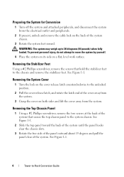
... from the system. See Figure 1-1. 4 Tower-to the unlocked position. 2 Pull the cover release latch, and rotate the latch end of the system that hold the stabilizer feet to the system chassis. See Figure 1-1. Preparing the System for ... remove the stabilizer feet. Removing the Top Chassis Panel 1 Using a #2 Phillips screwdriver, remove the two screws at the back of the cover away from the system. 3 Grasp the cover on the cover release latch counterclockwise to -Rack Conversion Guide WARNING: The system may weigh up to move the system by yourself. 4 Place the...
... from the system. See Figure 1-1. 4 Tower-to the unlocked position. 2 Pull the cover release latch, and rotate the latch end of the system that hold the stabilizer feet to the system chassis. See Figure 1-1. Preparing the System for ... remove the stabilizer feet. Removing the Top Chassis Panel 1 Using a #2 Phillips screwdriver, remove the two screws at the back of the cover away from the system. 3 Grasp the cover on the cover release latch counterclockwise to -Rack Conversion Guide WARNING: The system may weigh up to move the system by yourself. 4 Place the...
Tower-to-Rack Conversion Guide
Page 6
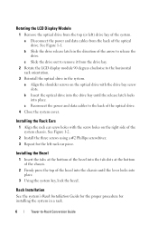
... bezel. Rack Installation See the system's Rack Installation Guide for the proper procedure for the left ) drive bay of the optical drive. 4 Close the system cover. See Figure 1-1. a Align the shoulder screws on the optical drive with the screw holes on the right side of the system chassis. b Slide the drive...
... bezel. Rack Installation See the system's Rack Installation Guide for the proper procedure for the left ) drive bay of the optical drive. 4 Close the system cover. See Figure 1-1. a Align the shoulder screws on the optical drive with the screw holes on the right side of the system chassis. b Slide the drive...
Hardware Owner's Manual
Page 12
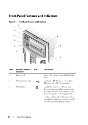
Front Panel Features and Indicators 7 6 5 8 4 3 9 2 1 10 Item Indicator, Button, or Icon Connector 1 Front bezel 2 USB connectors (2) 3 NMI button 3 Description Covers the system's front-loading hard drives. The ports are USB 2.0-complaint. Use this button only if directed to troubleshoot software and device driver errors when ...
Front Panel Features and Indicators 7 6 5 8 4 3 9 2 1 10 Item Indicator, Button, or Icon Connector 1 Front bezel 2 USB connectors (2) 3 NMI button 3 Description Covers the system's front-loading hard drives. The ports are USB 2.0-complaint. Use this button only if directed to troubleshoot software and device driver errors when ...
Hardware Owner's Manual
Page 36
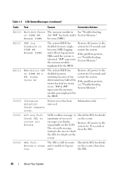
... the disabled memory system for 10 seconds and mirroring because it has restart the system. more. System Memory." System cover has been removed. E2113 Mem mirror OFF on the events. Check chassis cover. LCD overflow message. instructs the user to the sequentially on the events. "## & ##" System Memory." represents the memory- messages can...
... the disabled memory system for 10 seconds and mirroring because it has restart the system. more. System Memory." System cover has been removed. E2113 Mem mirror OFF on the events. Check chassis cover. LCD overflow message. instructs the user to the sequentially on the events. "## & ##" System Memory." represents the memory- messages can...
Hardware Owner's Manual
Page 79
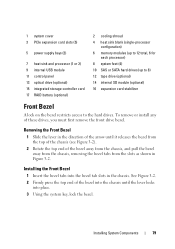
... Removing the Front Bezel 1 Slide the lever in the direction of the arrow until the lever locks into the bezel tab slots in Figure 3-2. 1 system cover 3 PCIe expansion card slots (5) 5 power supply bays (2) 7 heat sink and processor (1 or 2) 9 internal USB module 11 control panel 13 optical drive (optional) 15 integrated storage...
... Removing the Front Bezel 1 Slide the lever in the direction of the arrow until the lever locks into the bezel tab slots in Figure 3-2. 1 system cover 3 PCIe expansion card slots (5) 5 power supply bays (2) 7 heat sink and processor (1 or 2) 9 internal USB module 11 control panel 13 optical drive (optional) 15 integrated storage...
Hardware Owner's Manual
Page 81
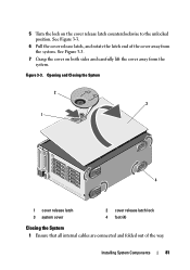
Installing System Components 81 Figure 3-3. Opening and Closing the System 2 3 1 4 1 cover release latch 3 system cover 2 cover release latch lock 4 foot (4) Closing the System 1 Ensure that all internal cables are connected and folded out of the cover away from the system. See Figure 3-3. 6 Pull the cover release latch, and rotate the latch end of the way. See Figure 3-3. 7 Grasp the cover on the cover release latch counterclockwise to the unlocked position. 5 Turn the lock on both sides and carefully lift the cover away from the system.
Installing System Components 81 Figure 3-3. Opening and Closing the System 2 3 1 4 1 cover release latch 3 system cover 2 cover release latch lock 4 foot (4) Closing the System 1 Ensure that all internal cables are connected and folded out of the cover away from the system. See Figure 3-3. 6 Pull the cover release latch, and rotate the latch end of the way. See Figure 3-3. 7 Grasp the cover on the cover release latch counterclockwise to the unlocked position. 5 Turn the lock on both sides and carefully lift the cover away from the system.
Hardware Owner's Manual
Page 82
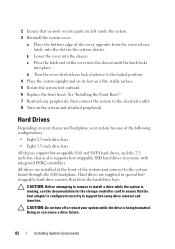
... hot-swappable SSD hard drives in the hard-drive bays. All drives are left inside the system. 3 Reinstall the system cover: a Place the bottom edge of the cover into the chassis until the latch locks into the chassis. See "Installing the Front Bezel." 7 Reattach any peripherals, then ...8 Turn on a flat, stable surface. 5 Rotate the system feet outward. 6 Replace the front bezel. c Press the latch end of the cover, opposite from the cover release latch, into the slots in the system chassis. 2 Ensure that the host adapter is configured correctly to support hot-swap drive removal and...
... hot-swappable SSD hard drives in the hard-drive bays. All drives are left inside the system. 3 Reinstall the system cover: a Place the bottom edge of the cover into the chassis until the latch locks into the chassis. See "Installing the Front Bezel." 7 Reattach any peripherals, then ...8 Turn on a flat, stable surface. 5 Rotate the system feet outward. 6 Replace the front bezel. c Press the latch end of the cover, opposite from the cover release latch, into the slots in the system chassis. 2 Ensure that the host adapter is configured correctly to support hot-swap drive removal and...
Hardware Owner's Manual
Page 120
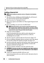
... be installed over empty expansion-card slots to remove the expansion card. CAUTION: Do not route card cables over the cards can prevent the system cover from the electrical outlet and peripherals. 2 Open the system. See the documentation that the card's metal tab is inserted in the system. Ensure that came...
... be installed over empty expansion-card slots to remove the expansion card. CAUTION: Do not route card cables over the cards can prevent the system cover from the electrical outlet and peripherals. 2 Open the system. See the documentation that the card's metal tab is inserted in the system. Ensure that came...
Hardware Owner's Manual
Page 131
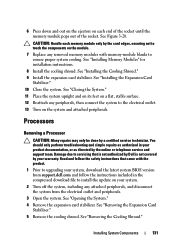
... on its feet on a flat, stable surface. 12 Reattach any attached peripherals, and disconnect the system from support.dell.com and follow the safety instructions that is not authorized by Dell is not covered by your warranty. CAUTION: Handle each end of the socket until the memory module pops out of the socket...
... on its feet on a flat, stable surface. 12 Reattach any attached peripherals, and disconnect the system from support.dell.com and follow the safety instructions that is not authorized by Dell is not covered by your warranty. CAUTION: Handle each end of the socket until the memory module pops out of the socket...
Hardware Owner's Manual
Page 134
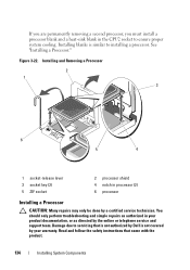
... warranty. Damage due to installing a processor. Read and follow the safety instructions that is not authorized by Dell is similar to servicing that came with the product. 134 Installing System Components Installing blanks is not covered by a certified service technician. Installing and Removing a Processor 2 1 3 6 5 4 1 socket-release lever 3 socket key (2) 5 ZIF socket 2 processor...
... warranty. Damage due to installing a processor. Read and follow the safety instructions that is not authorized by Dell is similar to servicing that came with the product. 134 Installing System Components Installing blanks is not covered by a certified service technician. Installing and Removing a Processor 2 1 3 6 5 4 1 socket-release lever 3 socket key (2) 5 ZIF socket 2 processor...
Hardware Owner's Manual
Page 138
... the online or telephone service and support team. Read and follow the safety instructions that the battery is not covered by a certified service technician. Damage due to servicing that is not authorized by Dell is operating properly. See "Opening the System." 138 Installing System Components See Figure 3-27. 13 Install the integrated...
... the online or telephone service and support team. Read and follow the safety instructions that the battery is not covered by a certified service technician. Damage due to servicing that is not authorized by Dell is operating properly. See "Opening the System." 138 Installing System Components See Figure 3-27. 13 Install the integrated...
Hardware Owner's Manual
Page 139
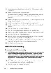
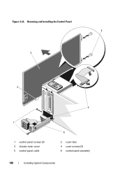
..., removing the metal hooks from the top side of the system. a Using a #2 Phillips screwdriver, remove the two hex-head Phillips screws securing the outer cover from the control panel board. See Figure 3-24. See Figure 3-24. 11 Remove the control panel cable from the back of the chassis to access..., and slide the expansion card stabilizer bracket up and out of the the chassis. CAUTION: Do not pull on the front edge of the cover, slide the cover slightly towards the back of the cable connector. See Figure 3-24. See Figure 3-24. 10 Slide the control panel assembly with the control ...
..., removing the metal hooks from the top side of the system. a Using a #2 Phillips screwdriver, remove the two hex-head Phillips screws securing the outer cover from the control panel board. See Figure 3-24. See Figure 3-24. 11 Remove the control panel cable from the back of the chassis to access..., and slide the expansion card stabilizer bracket up and out of the the chassis. CAUTION: Do not pull on the front edge of the cover, slide the cover slightly towards the back of the cable connector. See Figure 3-24. See Figure 3-24. 10 Slide the control panel assembly with the control ...
Hardware Owner's Manual
Page 140
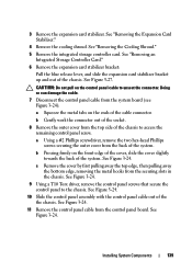
Figure 3-24. Removing and Installing the Control Panel 4 3 2 5 1 1 control panel screws (2) 3 chassis outer cover 5 control panel cable 6 2 cover tabs 4 cover screws (2) 6 control panel assembly 140 Installing System Components
Figure 3-24. Removing and Installing the Control Panel 4 3 2 5 1 1 control panel screws (2) 3 chassis outer cover 5 control panel cable 6 2 cover tabs 4 cover screws (2) 6 control panel assembly 140 Installing System Components
Hardware Owner's Manual
Page 141
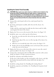
...the control panel cable to servicing that is not authorized by your product documentation, or as directed by a certified service technician. c Slide the cover towards the front of the chassis. See Figure 3-27. 8 Install the cooling shroud. Installing System Components 141 Installing the Control Panel Assembly CAUTION...You should only perform troubleshooting and simple repairs as authorized in the chassis, and slide the bracket downwards until it is not covered by Dell is fully seated against the front of the chassis. 3 Replace the Torx screw on the top side of the system to ...
...the control panel cable to servicing that is not authorized by your product documentation, or as directed by a certified service technician. c Slide the cover towards the front of the chassis. See Figure 3-27. 8 Install the cooling shroud. Installing System Components 141 Installing the Control Panel Assembly CAUTION...You should only perform troubleshooting and simple repairs as authorized in the chassis, and slide the bracket downwards until it is not covered by Dell is fully seated against the front of the chassis. 3 Replace the Torx screw on the top side of the system to ...
Hardware Owner's Manual
Page 142
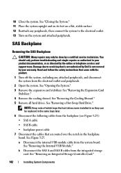
... from the backplane (see Figure 3-25): • SAS A cable • SAS B cable • backplane power cable 7 Disconnect the cables that is not authorized by Dell is not covered by your product documentation, or as directed by a certified service technician. See "Closing the System." 11 Place the system upright and on its feet...
... from the backplane (see Figure 3-25): • SAS A cable • SAS B cable • backplane power cable 7 Disconnect the cables that is not authorized by Dell is not covered by your product documentation, or as directed by a certified service technician. See "Closing the System." 11 Place the system upright and on its feet...
Hardware Owner's Manual
Page 144
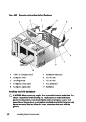
Figure 3-25. Removing and Installing the SAS Backplane 2 3 4 1 5 6 7 8 9 10 1 cables in your warranty. Read and follow the safety instructions that is not authorized by Dell is not covered by your product documentation, or as authorized in backplane notch 3 backplane notch 5 securing slot (8) 7 backplane power cable 9 backplane signal cable 2 backplane release pin 4 SAS A cable...
Figure 3-25. Removing and Installing the SAS Backplane 2 3 4 1 5 6 7 8 9 10 1 cables in your warranty. Read and follow the safety instructions that is not authorized by Dell is not covered by your product documentation, or as authorized in backplane notch 3 backplane notch 5 securing slot (8) 7 backplane power cable 9 backplane signal cable 2 backplane release pin 4 SAS A cable...

