

Glossary
Page 8
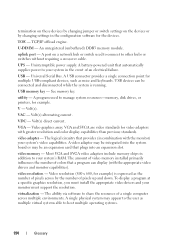
... last device at each processor has equal access to remotely monitor and manage workstations. When such devices are video standards for multiple USB-compliant devices, such as mice and keyboards. A port on a network hub or switch used . A battery-powered unit that tells a system what hardware is installed and how the system should...
... last device at each processor has equal access to remotely monitor and manage workstations. When such devices are video standards for multiple USB-compliant devices, such as mice and keyboards. A port on a network hub or switch used . A battery-powered unit that tells a system what hardware is installed and how the system should...

Hardware Owner's Manual
Page 12
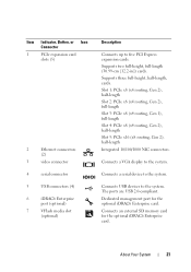
Front Panel Features and Indicators 7 6 5 8 4 3 9 2 1 10 Item Indicator, Button, or Icon Connector 1 Front bezel 2 USB connectors (2) Description Covers the system's front-loading hard drives. Connects USB devices to the system. Figure 1-1. The ports are USB 2.0-compliant. 12 About Your System The illustration in this section shows a system with an LCD panel. Front-Panel Features and Indicators NOTE: Depending on the configuration, your system may have an LCD panel or LED diagnostic indicators.
Front Panel Features and Indicators 7 6 5 8 4 3 9 2 1 10 Item Indicator, Button, or Icon Connector 1 Front bezel 2 USB connectors (2) Description Covers the system's front-loading hard drives. Connects USB devices to the system. Figure 1-1. The ports are USB 2.0-compliant. 12 About Your System The illustration in this section shows a system with an LCD panel. Front-Panel Features and Indicators NOTE: Depending on the configuration, your system may have an LCD panel or LED diagnostic indicators.
Hardware Owner's Manual
Page 21
... (x8 routing, Gen 2), half-length Integrated 10/100/1000 NIC connectors. Connects USB devices to the system. Connects a VGA display to the system. Dedicated management port for the optional iDRAC6 Enterprise card. About Your System 21 Item Indicator, Button, ...or Icon Connector 1 PCIe expansion card slots (5) 2 Ethernet connectors (2) 3 video connector 4 serial connector 5 USB connectors (4) 6 iDRAC6 Enterprise port (optional) 7 VFlash media slot (optional) Description Connects up to the system. Supports two full-height, full-length (30.99...
... (x8 routing, Gen 2), half-length Integrated 10/100/1000 NIC connectors. Connects USB devices to the system. Connects a VGA display to the system. Dedicated management port for the optional iDRAC6 Enterprise card. About Your System 21 Item Indicator, Button, ...or Icon Connector 1 PCIe expansion card slots (5) 2 Ethernet connectors (2) 3 video connector 4 serial connector 5 USB connectors (4) 6 iDRAC6 Enterprise port (optional) 7 VFlash media slot (optional) Description Connects up to the system. Supports two full-height, full-length (30.99...

Hardware Owner's Manual
Page 48
... configuration. Manufacturing mode detected System is physically available. Memory Initialization Warning: Memory size may not work because all user accessible USB ports are installed in the system BIOS. Power down and restart the system from the power button, and then enter the System...on page 106. 48 About Your System If operating locally, power cycle the system and enter system setup program to enable the USB port(s). "General Memory Module Installation Guidelines" on page 62. See "General Memory Module Installation Guidelines" on failed keyboard connector. System Messages...
... configuration. Manufacturing mode detected System is physically available. Memory Initialization Warning: Memory size may not work because all user accessible USB ports are installed in the system BIOS. Power down and restart the system from the power button, and then enter the System...on page 106. 48 About Your System If operating locally, power cycle the system and enter system setup program to enable the USB port(s). "General Memory Module Installation Guidelines" on page 62. See "General Memory Module Installation Guidelines" on failed keyboard connector. System Messages...
Hardware Owner's Manual
Page 51
... Figure 6-1 for the appropriate drive(s) installed in your system. Read fault Requested sector not found to the specified SATA port. Ensure that the USB the system could not find a cables, SAS/SATA backplane particular sector on page 167 for jumper location. Quad rank .... device not found The operating system cannot Replace the optical medium, read from the hard drive, USB medium, or USB optical drive, or USB device, device. See defective. SATA Port x There is are installed in initializing PCIe device; Install the NVRAM_CLR jumper in socket. Ensure that...
... Figure 6-1 for the appropriate drive(s) installed in your system. Read fault Requested sector not found to the specified SATA port. Ensure that the USB the system could not find a cables, SAS/SATA backplane particular sector on page 167 for jumper location. Quad rank .... device not found The operating system cannot Replace the optical medium, read from the hard drive, USB medium, or USB optical drive, or USB device, device. See defective. SATA Port x There is are installed in initializing PCIe device; Install the NVRAM_CLR jumper in socket. Ensure that...
Hardware Owner's Manual
Page 69
Integrated Devices Screen Option Description User Accessible USB Ports Enables or disables the user accessible USB ports. (All Ports On default) Options are Enabled, Enabled with PXE, and Enabled with iSCSI Boot. The NICs may also be enabled if the hardware ...is allowed to initialize the timer. Options are All Ports On, Only Back Ports On, and All Ports Off. MAC Address Displays the MAC address for activity, and aids in the embedded video controller. Internal USB Port 1 (On default) Enables or disables the internal USB port. Embedded Video Controller (Enabled default) Displays the ...
Integrated Devices Screen Option Description User Accessible USB Ports Enables or disables the user accessible USB ports. (All Ports On default) Options are Enabled, Enabled with PXE, and Enabled with iSCSI Boot. The NICs may also be enabled if the hardware ...is allowed to initialize the timer. Options are All Ports On, Only Back Ports On, and All Ports Off. MAC Address Displays the MAC address for activity, and aids in the embedded video controller. Internal USB Port 1 (On default) Enables or disables the internal USB port. Embedded Video Controller (Enabled default) Displays the ...
Hardware Owner's Manual
Page 126
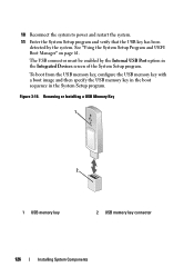
... Setup Program and UEFI Boot Manager" on page 61. Figure 3-18. To boot from the USB memory key, configure the USB memory key with a boot image and then specify the USB memory key in the boot sequence in the Integrated Devices screen of the System Setup program. Removing... or Installing a USB Memory Key 1 2 1 USB memory key 2 USB memory key connector 126 Installing System Components 10 Reconnect the system to power and restart the system. 11 Enter the System Setup program and verify that the USB key has been detected by the Internal USB Port option in the System Setup...
... Setup Program and UEFI Boot Manager" on page 61. Figure 3-18. To boot from the USB memory key, configure the USB memory key with a boot image and then specify the USB memory key in the boot sequence in the Integrated Devices screen of the System Setup program. Removing... or Installing a USB Memory Key 1 2 1 USB memory key 2 USB memory key connector 126 Installing System Components 10 Reconnect the system to power and restart the system. 11 Enter the System Setup program and verify that the USB key has been detected by the Internal USB Port option in the System Setup...

Hardware Owner's Manual
Page 158
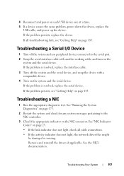
...functioning, enter the system setup program. If the tests run successfully, the problem is not related to the system. 2 Power down all USB ports are enabled. a Disconnect the keyboard and mouse cables from the system briefly and reconnect them from the system to step 2. b Connect ...settings. 156 Troubleshooting Your System If the problem is not accessible, see "Getting Help" on page 185 Troubleshooting a USB Device 1 Use the following steps to the USB port(s) on setting the NVRAM_CLR jumper inside your keyboard is resolved, restart the system, enter the System Setup program, ...
...functioning, enter the system setup program. If the tests run successfully, the problem is not related to the system. 2 Power down all USB ports are enabled. a Disconnect the keyboard and mouse cables from the system briefly and reconnect them from the system to step 2. b Connect ...settings. 156 Troubleshooting Your System If the problem is not accessible, see "Getting Help" on page 185 Troubleshooting a USB Device 1 Use the following steps to the USB port(s) on setting the NVRAM_CLR jumper inside your keyboard is resolved, restart the system, enter the System Setup program, ...
Hardware Owner's Manual
Page 159
.... 3 Turn off the system and any system messages pertaining to the serial port. 2 Swap the serial interface cable with a comparable device. 4 Turn on each USB device one at a time. 5 If a device causes the same problem, power down the device, replace the USB cable, and power up the device. If the problem persists, see...
.... 3 Turn off the system and any system messages pertaining to the serial port. 2 Swap the serial interface cable with a comparable device. 4 Turn on each USB device one at a time. 5 If a device causes the same problem, power down the device, replace the USB cable, and power up the device. If the problem persists, see...
Hardware Owner's Manual
Page 160
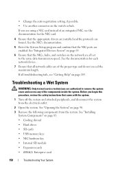
...69. 6 Ensure that the NICs, hubs, and switches on page 83. • Cooling shroud • Hard drives • SD cards • USB memory keys • NIC hardware key • Internal SD module • Expansion cards • iDRAC6 Enterprise card 158 Troubleshooting Your System See the documentation ... the system from the system. Before you are all troubleshooting fails, see the documentation for each network device. 7 Ensure that the NIC ports are of the proper type and do not exceed the maximum length. See "Installing System Components" on the network are using a NIC card...
...69. 6 Ensure that the NICs, hubs, and switches on page 83. • Cooling shroud • Hard drives • SD cards • USB memory keys • NIC hardware key • Internal SD module • Expansion cards • iDRAC6 Enterprise card 158 Troubleshooting Your System See the documentation ... the system from the system. Before you are all troubleshooting fails, see the documentation for each network device. 7 Ensure that the NIC ports are of the proper type and do not exceed the maximum length. See "Installing System Components" on the network are using a NIC card...
Hardware Owner's Manual
Page 166
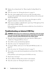
... modules have been checked, see "Getting Help." See "Closing the System" on the front of the components inside the system. Troubleshooting an Internal USB Key WARNING: Only trained service technicians are authorized to the electrical outlet, and turn on a flat and stable surface, reconnect the system to remove... the system cover and access any error message that the USB key port is functioning. See "Closing the System" on page 91. 21 Place the system upright and on its feet on the system and attached...
... modules have been checked, see "Getting Help." See "Closing the System" on the front of the components inside the system. Troubleshooting an Internal USB Key WARNING: Only trained service technicians are authorized to the electrical outlet, and turn on a flat and stable surface, reconnect the system to remove... the system cover and access any error message that the USB key port is functioning. See "Closing the System" on page 91. 21 Place the system upright and on its feet on the system and attached...
Hardware Owner's Manual
Page 189
...American National Standards Institute. A copy of the system that allows the processor to the system. BMC - Baseboard management controller. A CD, diskette, or USB memory key that contains a processor, memory, and a hard drive. Your system contains an expansion bus that contains indicators and controls, such as the... power button and power indicator. Your system also contains an address bus and a data bus for the serial ports on a regular basis. The part of a program or data file. A chip or expansion card that relieves the system's processor of data...
...American National Standards Institute. A copy of the system that allows the processor to the system. BMC - Baseboard management controller. A CD, diskette, or USB memory key that contains a processor, memory, and a hard drive. Your system contains an expansion bus that contains indicators and controls, such as the... power button and power indicator. Your system also contains an address bus and a data bus for the serial ports on a regular basis. The part of a program or data file. A chip or expansion card that relieves the system's processor of data...
Hardware Owner's Manual
Page 196
...- Most VGA and SVGA video adapters include memory chips in the event of an electrical failure. video resolution - U-DIMM - USB devices can display (with the appropriate video drivers and monitor capabilities). See memory key. Volt(s) direct current. The logical circuitry that... hub or switch used to other hubs or switches without requiring a crossover cable. uplink port - A USB connector provides a single connection point for example) is running. VAC - video memory - USB memory key - A single physical system may be integrated into an expansion slot. utility ...
...- Most VGA and SVGA video adapters include memory chips in the event of an electrical failure. video resolution - U-DIMM - USB devices can display (with the appropriate video drivers and monitor capabilities). See memory key. Volt(s) direct current. The logical circuitry that... hub or switch used to other hubs or switches without requiring a crossover cable. uplink port - A USB connector provides a single connection point for example) is running. VAC - video memory - USB memory key - A single physical system may be integrated into an expansion slot. utility ...


