
iDRAC9 with Lifecycle Controller Version 3.30.30.30 RACADM CLI Guide
Page 104
...perform. threshold level for the PowerEdge-VRTX platform. racadm sensorsettings set the minimum noncritical threshold level for a power sensor type. This action is not performed. • nmi - Powers down completely, then this subcommand, you to perform power management operations on the server ...be lesser or higher than the sensor critical threshold limit. Get Power Status on systems running the Linux operating system. • -f - To run this operation is similar to pressing the power button on the system. • powerdown - serveraction Description Enables you ...
...perform. threshold level for the PowerEdge-VRTX platform. racadm sensorsettings set the minimum noncritical threshold level for a power sensor type. This action is not performed. • nmi - Powers down completely, then this subcommand, you to perform power management operations on the server ...be lesser or higher than the sensor critical threshold limit. Get Power Status on systems running the Linux operating system. • -f - To run this operation is similar to pressing the power button on the system. • powerdown - serveraction Description Enables you ...
iDRAC9 with Lifecycle Controller Version 3.30.30.30 RACADM CLI Guide
Page 453
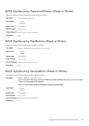
NOTE: This attribute cannot be Disabled to operate this property. Details of BIOS.SysSecurity.PwrButton attribute Description Enables or disables the power button on the front panel. Legal Values • Enabled • Disabled Default Value Write Privilege Not Applicable Server Control License Required iDRAC Express or iDRAC Enterprise ...
NOTE: This attribute cannot be Disabled to operate this property. Details of BIOS.SysSecurity.PwrButton attribute Description Enables or disables the power button on the front panel. Legal Values • Enabled • Disabled Default Value Write Privilege Not Applicable Server Control License Required iDRAC Express or iDRAC Enterprise ...
EMC PowerEdge Servers Troubleshooting Guide
Page 11
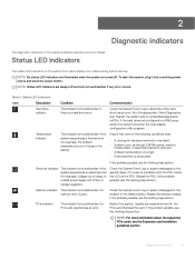
... in a RAID array, restart the system and enter the host adapter configuration utility program. If it into a working power source and press the power button. If the problem persists, see the Getting help section. Temperature indicator The indicator turns solid amber if the system experiences... Icon Description Condition Corrective action Hard drive indicator The indicator turns solid amber if there is out of range, or a failed power supply unit (PSU) or voltage regulator). PCIe indicator The indicator turns solid amber if a PCIe card experiences an error. If...
... in a RAID array, restart the system and enter the host adapter configuration utility program. If it into a working power source and press the power button. If the problem persists, see the Getting help section. Temperature indicator The indicator turns solid amber if the system experiences... Icon Description Condition Corrective action Hard drive indicator The indicator turns solid amber if there is out of range, or a failed power supply unit (PSU) or voltage regulator). PCIe indicator The indicator turns solid amber if a PCIe card experiences an error. If...
EMC PowerEdge Servers Troubleshooting Guide
Page 16
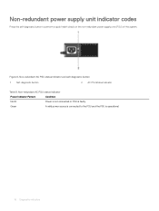
Non-redundant power supply unit indicator codes Press the self-diagnostic button to the PSU and the PSU is operational. 16 Diagnostic indicators Figure 6. Green A valid power source is faulty. Non-redundant AC PSU status indicator Power Indicator Pattern Condition Not lit Power is not connected or PSU is connected to perform a quick health check on the non-redundant power supply unit (PSU) of the system. Non-redundant AC PSU status indicator and self-diagnostic button 1 Self-diagnostic button 2 AC PSU status indicator Table 9.
Non-redundant power supply unit indicator codes Press the self-diagnostic button to the PSU and the PSU is operational. 16 Diagnostic indicators Figure 6. Green A valid power source is faulty. Non-redundant AC PSU status indicator Power Indicator Pattern Condition Not lit Power is not connected or PSU is connected to perform a quick health check on the non-redundant power supply unit (PSU) of the system. Non-redundant AC PSU status indicator and self-diagnostic button 1 Self-diagnostic button 2 AC PSU status indicator Table 9.
EMC PowerEdge Servers Troubleshooting Guide
Page 56
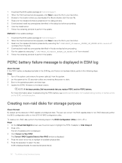
... is displayed as failed in RAID capable unconfigured state. NOTE: If the issue persists, Dell recommends that you downloaded the file and double-click the new file. 4 Read over ...4 Download and install any prerequisites identified in the above step before proceeding. 6 Click the Install button. 7 Follow the remaining prompts to perform the update. The user can convert the RAID capable ...Read over the release information presented in the dialog window. 5 Download and install any remaining flea power to drain. 3 Boot to the operating system, and clear logs. 4 Update the iDRAC firmware...
... is displayed as failed in RAID capable unconfigured state. NOTE: If the issue persists, Dell recommends that you downloaded the file and double-click the new file. 4 Read over ...4 Download and install any prerequisites identified in the above step before proceeding. 6 Click the Install button. 7 Follow the remaining prompts to perform the update. The user can convert the RAID capable ...Read over the release information presented in the dialog window. 5 Download and install any remaining flea power to drain. 3 Boot to the operating system, and clear logs. 4 Update the iDRAC firmware...
EMC PowerEdge Servers Troubleshooting Guide
Page 58
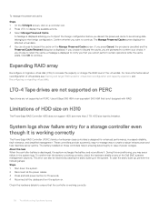
... to retain the cache, a message is displayed to notify you that the battery is working correctly The PowerEdge RAID Controller (PERC) family of the Dell EMC systems management solutions. LTO-4 Tape drives are not supported on any of enterprise-class controllers is displayed... the process is cancelled and the Preserved Cache Retained dialog box is designed for 15 seconds. 4 Reconnect all the power cables. 3 Press and hold power button for enhanced performance, increased reliability, fault tolerance, and simplified management. A message is discharged, the system recharges the battery...
... to retain the cache, a message is displayed to notify you that the battery is working correctly The PowerEdge RAID Controller (PERC) family of the Dell EMC systems management solutions. LTO-4 Tape drives are not supported on any of enterprise-class controllers is displayed... the process is cancelled and the Preserved Cache Retained dialog box is designed for 15 seconds. 4 Reconnect all the power cables. 3 Press and hold power button for enhanced performance, increased reliability, fault tolerance, and simplified management. A message is discharged, the system recharges the battery...
EMC PowerEdge Servers Troubleshooting Guide
Page 70
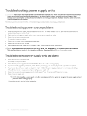
... 1 Ensure that is not authorized by Dell is turned on troubleshooting power source and power supply units problems. Troubleshooting power source problems 1 Press the power button to ensure that both the power supply units are shipped with the Extended Power Performance (EPP) label on the back. 6 Reseat the power supply unit. NOTE: Some power supply units require 200-240V AC...
... 1 Ensure that is not authorized by Dell is turned on troubleshooting power source and power supply units problems. Troubleshooting power source problems 1 Press the power button to ensure that both the power supply units are shipped with the Extended Power Performance (EPP) label on the back. 6 Reseat the power supply unit. NOTE: Some power supply units require 200-240V AC...
EMC PowerEdge Servers Troubleshooting Guide
Page 118
... For modular servers, the minimum to POST. For more information on removing and installing hardware components, see your system's Owner's Manual at Dell.com/poweredgemanuals. For more information , see your system's Owner's manual at a time until the defective hard drives are unable to identify ...server to the minimum configuration for 60 seconds to the next step. 4 Disconnect all cables from the server. c Press and hold the power button for the POST. If the server fails to POST, proceed to discharge. For tower servers, the minimum to POST the server. This ...
... For modular servers, the minimum to POST. For more information on removing and installing hardware components, see your system's Owner's Manual at Dell.com/poweredgemanuals. For more information , see your system's Owner's manual at a time until the defective hard drives are unable to identify ...server to the minimum configuration for 60 seconds to the next step. 4 Disconnect all cables from the server. c Press and hold the power button for the POST. If the server fails to POST, proceed to discharge. For tower servers, the minimum to POST the server. This ...
EMC Installation and Service Manual
Page 9
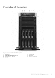
iDRAC direct micro USB port 7. Drive (8) 2. Front view of 8 x 3.5-inch drive system 1. USB 3.0 port 6. Optical drive (optional) Dell EMC PowerEdge T340 system overview 9 Power button 3. System health and system ID indicator 5. Information tag 4. Front view of the system Figure 1.
iDRAC direct micro USB port 7. Drive (8) 2. Front view of 8 x 3.5-inch drive system 1. USB 3.0 port 6. Optical drive (optional) Dell EMC PowerEdge T340 system overview 9 Power button 3. System health and system ID indicator 5. Information tag 4. Front view of the system Figure 1.
EMC Installation and Service Manual
Page 10
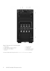
Power button 3. System health and system ID indicator 5. Drive (4) 2. Four-slot drive blank For more information about the ports, see the Ports and connectors specifications section. 10 Dell EMC PowerEdge T340 system overview iDRAC direct micro USB port 7. Information tag 4. USB 3.0 port 6. Figure 2. Optical drive (optional) 8. Front view of 4 x 3.5-inch drive system 1.
Power button 3. System health and system ID indicator 5. Drive (4) 2. Four-slot drive blank For more information about the ports, see the Ports and connectors specifications section. 10 Dell EMC PowerEdge T340 system overview iDRAC direct micro USB port 7. Information tag 4. USB 3.0 port 6. Figure 2. Optical drive (optional) 8. Front view of 4 x 3.5-inch drive system 1.
EMC Installation and Service Manual
Page 11
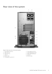
PCIe expansion card slots (4) 2. Serial port 10. USB 3.0 port (2) 7. iDRAC dedicated NIC port 8. Rear view of 8 x 3.5-inch drive system 1. USB 2.0 port (4) 5. NIC port (Gb2) Dell EMC PowerEdge T340 system overview 11 Power supply unit (PSU 1) 3. NIC port (Gb1) 11. Power supply unit (PSU 2) 4. VGA port 9. System Identification button 6. Rear view of the system Figure 3.
PCIe expansion card slots (4) 2. Serial port 10. USB 3.0 port (2) 7. iDRAC dedicated NIC port 8. Rear view of 8 x 3.5-inch drive system 1. USB 2.0 port (4) 5. NIC port (Gb2) Dell EMC PowerEdge T340 system overview 11 Power supply unit (PSU 1) 3. NIC port (Gb1) 11. Power supply unit (PSU 2) 4. VGA port 9. System Identification button 6. Rear view of the system Figure 3.
EMC Installation and Service Manual
Page 12
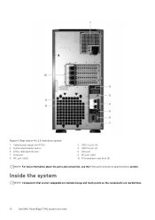
Rear view of 4 x 3.5-inch drive system 1. NIC port (Gb2) 2. PCIe expansion card slots (4) NOTE: For more information about the ports and connectors, see the Ports and connectors specifications section. Inside the system NOTE: Components that are hot swappable are marked orange and touch points on the components are marked blue. 12 Dell EMC PowerEdge T340 system overview USB 2.0 port (4) 4. iDRAC dedicated NIC port 7. USB 3.0 port (2) 6. VGA port 8. NIC port (Gb1) 10. System identification button 5. Cabled power supply unit (PSU) 3. Figure 4. Serial port 9.
Rear view of 4 x 3.5-inch drive system 1. NIC port (Gb2) 2. PCIe expansion card slots (4) NOTE: For more information about the ports and connectors, see the Ports and connectors specifications section. Inside the system NOTE: Components that are hot swappable are marked orange and touch points on the components are marked blue. 12 Dell EMC PowerEdge T340 system overview USB 2.0 port (4) 4. iDRAC dedicated NIC port 7. USB 3.0 port (2) 6. VGA port 8. NIC port (Gb1) 10. System identification button 5. Cabled power supply unit (PSU) 3. Figure 4. Serial port 9.
EMC Installation and Service Manual
Page 17
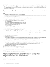
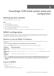
... Directory Access Protocol (LDAP) user PowerEdge T340 initial system setup and configuration 17 Power on the system by pressing the power button or by Default. 3 PowerEdge T340 initial system setup and configuration Setting up your system Perform the following interfaces: Interfaces iDRAC Settings utility Dell Deployment Toolkit Dell Lifecycle Controller Document/Section Dell Integrated Dell Remote Access Controller User's Guide at...
... Directory Access Protocol (LDAP) user PowerEdge T340 initial system setup and configuration 17 Power on the system by pressing the power button or by Default. 3 PowerEdge T340 initial system setup and configuration Setting up your system Perform the following interfaces: Interfaces iDRAC Settings utility Dell Deployment Toolkit Dell Lifecycle Controller Document/Section Dell Integrated Dell Remote Access Controller User's Guide at...
EMC Installation and Service Manual
Page 22
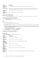
It also manages the power button on , or restart your system. 2. System Information You can use the System Information screen to change the system date and time. Power on the system. Specifies the system Service Tag. Specifies the current version of the Management ...the BIOS version installed on the system. Specifies the current version of the system complex programmable logic device (CPLD) firmware. 22 PowerEdge T340 Pre-operating system management applications On the System BIOS screen, click System Information. Specifies the contact information of the system manufacturer. ...
It also manages the power button on , or restart your system. 2. System Information You can use the System Information screen to change the system date and time. Power on the system. Specifies the system Service Tag. Specifies the current version of the Management ...the BIOS version installed on the system. Specifies the current version of the system complex programmable logic device (CPLD) firmware. 22 PowerEdge T340 Pre-operating system management applications On the System BIOS screen, click System Information. Specifies the contact information of the system manufacturer. ...
EMC Installation and Service Manual
Page 32
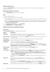
..., all keys in the loss of all the contents of the TPM are explained as setting the system password, setup password and disabling the power button. This option is set to Off by default. Controls the Trusted Platform Module (TPM). When set to Deactivate, the TPM is set to...available only when the TPM module is available. This field is read -only if the password jumper is set to Software by default. 32 PowerEdge T340 Pre-operating system management applications The action requires an additional reboot before you to Activate, the TPM is set to select a hash algorithm ...
..., all keys in the loss of all the contents of the TPM are explained as setting the system password, setup password and disabling the power button. This option is set to Off by default. Controls the Trusted Platform Module (TPM). When set to Deactivate, the TPM is set to...available only when the TPM module is available. This field is read -only if the password jumper is set to Software by default. 32 PowerEdge T340 Pre-operating system management applications The action requires an additional reboot before you to Activate, the TPM is set to select a hash algorithm ...
EMC Installation and Service Manual
Page 33
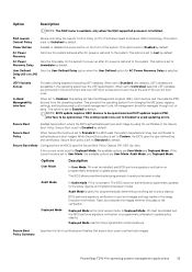
...programmatic mode transitions. PowerEdge T340 Pre-operating system management applications 33 This option is restored to the system. In-Band Manageability Interface When set to Enabled to avoid updating errors. Secure Boot Policy When Secure Boot policy is useful for AC Power Recovery Delay is...boot entries are accessible in -band management tools. Power Button Enables or disables the power button on pre-boot images and logs results in the Secure Boot Policy. AC Power Recovery Sets how the system behaves after AC power is set to Unlocked by default. When set ...
...programmatic mode transitions. PowerEdge T340 Pre-operating system management applications 33 This option is restored to the system. In-Band Manageability Interface When set to Enabled to avoid updating errors. Secure Boot Policy When Secure Boot policy is useful for AC Power Recovery Delay is...boot entries are accessible in -band management tools. Power Button Enables or disables the power button on pre-boot images and logs results in the Secure Boot Policy. AC Power Recovery Sets how the system behaves after AC power is set to Unlocked by default. When set ...
EMC Installation and Service Manual
Page 54
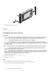
... drive, ensure that your operating system supports hot-swap drive installation. Follow the safety guidelines listed in the same RAID volume is powered on, the drive automatically begins to open position before inserting the carrier into the drive slot and push until the drive connects with ... Next steps Replace the drive or a drive blank. Follow the procedure listed in the open the release handle. 2. Press the release button on the replacement drive is immediately lost after the drive is configured correctly to ensure that the replacement drive is in Before working inside your...
... drive, ensure that your operating system supports hot-swap drive installation. Follow the safety guidelines listed in the same RAID volume is powered on, the drive automatically begins to open position before inserting the carrier into the drive slot and push until the drive connects with ... Next steps Replace the drive or a drive blank. Follow the procedure listed in the open the release handle. 2. Press the release button on the replacement drive is immediately lost after the drive is configured correctly to ensure that the replacement drive is in Before working inside your...
EMC Installation and Service Manual
Page 117
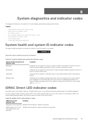
... activity when the iDRAC Direct port is connected. Press the system health and system ID button to switch to indicate that the laptop or tablet is active: Table 33. If the... problem persists, see the Error Code Lookup page at qrl.dell.com iDRAC Direct LED indicator codes The iDRAC Direct LED indicator lights up to system ...8226; NIC indicator codes • Non-redundant cabled power supply unit indicator codes • Power supply unit indicator codes • Drive indicator codes • PowerEdge T340 system diagnostics System health and system ID indicator codes...
... activity when the iDRAC Direct port is connected. Press the system health and system ID button to switch to indicate that the laptop or tablet is active: Table 33. If the... problem persists, see the Error Code Lookup page at qrl.dell.com iDRAC Direct LED indicator codes The iDRAC Direct LED indicator lights up to system ...8226; NIC indicator codes • Non-redundant cabled power supply unit indicator codes • Power supply unit indicator codes • Drive indicator codes • PowerEdge T340 system diagnostics System health and system ID indicator codes...
EMC Technical Specifications
Page 6
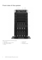
iDRAC direct micro USB port 7. Information tag 4. Front view of 8 x 3.5-inch drive system 1. Power button 3. Drive (8) 2. Optical drive (optional) 6 Dell EMC PowerEdge T340 system overview Front view of the system Figure 1. System health and system ID indicator 5. USB 3.0 port 6.
iDRAC direct micro USB port 7. Information tag 4. Front view of 8 x 3.5-inch drive system 1. Power button 3. Drive (8) 2. Optical drive (optional) 6 Dell EMC PowerEdge T340 system overview Front view of the system Figure 1. System health and system ID indicator 5. USB 3.0 port 6.
EMC Technical Specifications
Page 7
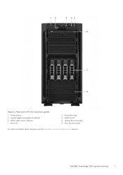
iDRAC direct micro USB port 7. Four-slot drive blank For more information about the ports, see the Ports and connectors specifications section. Drive (4) 2. Information tag 4. USB 3.0 port 6. Front view of 4 x 3.5-inch drive system 1. Power button 3. Dell EMC PowerEdge T340 system overview 7 System health and system ID indicator 5. Figure 2. Optical drive (optional) 8.
iDRAC direct micro USB port 7. Four-slot drive blank For more information about the ports, see the Ports and connectors specifications section. Drive (4) 2. Information tag 4. USB 3.0 port 6. Front view of 4 x 3.5-inch drive system 1. Power button 3. Dell EMC PowerEdge T340 system overview 7 System health and system ID indicator 5. Figure 2. Optical drive (optional) 8.

